Closed Loop Micro Reference Feedback Control for Anodic Lithium Plating Prevention
Micro-reference electrodes dynamically regulate charging current to pin anode potential above zero volts, preventing lithium plating without cycle-life loss.

Tap
In conventional two-electrode lithium-ion cells, terminal voltage reflects the combined potentials of both electrodes alongside internal ohmic drops, obscuring the negative electrode potential that actually dictates fast-charging limits. At high charge rates, that aggregate reading conceals where the graphite or silicon-graphite composite sits relative to Li/Li+. Whenever charge-transfer overpotentials and solid-state diffusion resistance outpace intercalation, the anode dips below 0.00 V versus Li/Li+, making the reduction of lithium ions into metallic lithium thermodynamically favorable on the carbon surface.
Embedding an isolated electrochemical reference probe directly in the jelly roll or electrode stack eliminates this blind spot, feeding real-time negative electrode potentials straight to the battery management system.
Measuring this potential directly removes the need for conservative lookup tables. Standard fast-charge profiles step down constant current at fixed intervals based on temperature and estimated state of charge, guarding against worst-case cell variations at the expense of extending charge times by 20 to 45 percent. Micro-reference feedback swaps those open-loop tables for continuous current throttling that pins the negative electrode to a 10 to 50 mV floor versus Li/Li+.
Charging current then tracks the kinetic ceiling of the anode across the operating temperature range without straying into the plating zone.
Holding the negative electrode potential 15 mV above Li/Li+ at 10 degrees Celsius shortens 10-to-80 percent charge times by 28 percent while eliminating metallic deposition.
Probe placement determines whether the signal is physically meaningful. Shifting a micro-reference toward the cell perimeter or out into the electrolyte reservoir distorts ionic pathways and introduces geometric shielding errors. Because the probe samples solution potential purely at its own coordinate, placing it outside the active inter-electrode gap registers fringe currents instead of intercalation kinetics.
Reliable feedback requires an ultra-thin wire set between the separator sheets, centered squarely between the facing anode and cathode coatings.
The probe alloy also has to stay stable in organic carbonate electrolytes without dissolving or poisoning adjacent active material. Pure metallic lithium ribbon deforms under stack pressure and passivates quickly in fluorinated alkyl carbonates, driving voltage drift past 30 mV within several hundred operating hours. Lithiated alloys offer far better phase stability and steadier thermodynamic potentials: lithiated gold micro-wires, lithium-bismuth, and partially delithiated lithium iron phosphate micro-coatings all function as workable pseudo-reference electrodes.
The alloy choice dictates baseline drift, internal impedance, and the handling difficulty on high-speed winding lines.
| Reference Alloy System | Baseline Potential vs Li/Li+ (V) | Drift Rate (mV per 1000h) | Probe Diameter (microns) | Equilibration Time (hours) |
|---|---|---|---|---|
| Lithium Metal (Li) | 0.000 | 12 to 45 | 80 to 150 | 0.5 |
| Lithium Gold (Li-Au) | 0.325 | 1.5 to 4.0 | 25 to 50 | 6.0 |
| Lithium Bismuth (Li-Bi) | 0.810 | 0.8 to 2.2 | 30 to 60 | 12.0 |
| Lithium Iron Phosphate (LFP) | 3.420 | 0.4 to 1.1 | 15 to 40 | 2.0 |
Inserting any wire into the active stack creates a local pressure spike. The probe’s physical profile pinches the porous polyolefin separator, reducing local porosity, increasing tortuosity, and driving up ionic resistance right along the wire track. When wire diameter exceeds 50 microns, adjacent graphite experiences severe current crowding along the contour.
That localized polarization inversion ends up triggering the exact lithium plating the probe was installed to prevent.
Underestimating probe thickness or baseline drift leads to premature dry-out and thermal runaway in tightly packaged modules.


Gradient
Current density distributes unevenly across commercial electrode sheets, which warps local overpotentials. In large prismatic and pouch cells above 50 Ah, current entering through copper and aluminum foil tabs creates planar ohmic drops across the current collectors. Because of these gradients, the anode potential near the tab margin diverges sharply from the potential at the bottom center of the sheet.
A single reference electrode placed at an arbitrary point samples only one coordinate of a broad, continuous potential field.

Does Anodic Polarization Inversion Precede Lithium Deposition?
Plating begins the moment interfacial overpotential drops below the lithium reduction baseline. Solid-state diffusion of lithium into graphite carries an activation barrier of 30 to 40 kJ/mol, whereas metallic reduction proceeds via rapid outer-sphere charge transfer. When aggressive current steps push local overpotentials below zero, metallic adatoms nucleate before lithium can intercalate, draining cyclable inventory with each charge cycle.
Depending on local current density and surface tension, these adatoms develop into mossy patches or sharp dendritic whiskers.
Interfacial overpotential inverts well before any signature appears in bulk cell voltage. Microscopic plating typically leads detectable terminal anomalies by tens or hundreds of seconds, masked entirely on full-cell voltage curves by cathode impedance. The physical progression follows several discrete interfacial stages:
- Interfacial charge-transfer saturation occurs when current density surpasses the exchange current density of the graphite surface film, causing total overpotentials to shift negative.
- Lithium adatom nucleation begins within microscopic surface defects of the carbon particles where localized electric field concentration lowers the nucleation barrier.
- Parasitic electrolyte consumption accelerates as newly formed metallic lithium reacts spontaneously with ethylene carbonate and dimethyl carbonate solvents.
- Porous dendrite growth extends through the separator pores toward the positive counter-electrode, increasing internal short-circuit probability and cell self-discharge.
Plated lithium reacts directly with liquid electrolyte, thickening the solid electrolyte interphase while consuming active cyclable inventory and drying out solvent. Although part of the deposited metal strips back during subsequent discharge, another portion disconnects electronically from the graphite matrix to form dead lithium. These isolated metallic clusters remain trapped within the passivation layer, pulling coulombic efficiency down from baseline figures of 99.98 percent to 98.50 percent or lower.
UL 1642 construction audits mandate internal mechanical clearances that micro-reference lead routings frequently breach unless recessed into the separator margin.
Core-to-surface temperature gradients further distort the polarization landscape. Heat builds up in the center of the roll, where conductive dissipation through cell packaging is poorest; during a 2C charge, the core of a 100 Ah prismatic cell routinely runs 8 to 15 degrees Celsius above its exterior faces. The cooler outer layers suffer sluggish charge transfer and solid-state diffusion, making electrode margins the primary sites for lithium plating.
A probe installed only in the warm core will read safe, positive potentials while outer windings actively plate. Addressing this mismatch requires multi-point reference taps or thermal-electrochemical models calibrated against physical sensor data.
Whether tab-induced ohmic drops or separator pinch points under winding tension trigger the initial plating remains an unsettled dispute in large-format cell design.

Governor
Regulation loops require analog front ends with exceptionally high input impedance. Pulling even minute currents through a micro-reference alters its surface stoichiometry, drifting the equilibrium potential and corrupting feedback. Specialized evaluation boards run input stages rated above 10 gigohms to hold leakage currents within picoampere limits.
The resulting potential difference between the negative current collector and the reference feeds directly into a proportional-integral-derivative loop or an active state observer.
To track the anode potential accurately, the controller adjusts pulse-width modulated current commands at the charger. While the anode stays above its protection setpoint ~ usually 15 to 20 mV versus Li/Li+ ~ the system delivers maximum current. As solid-state saturation drags the potential toward that lower boundary, the feedback loop trims current in real time, pinning the negative electrode right to the voltage floor without interrupting the charge.
Control algorithms that maintain a hard voltage buffer above zero volts sacrifice charging speed while preventing mossy dendrite nucleation.
In bench evaluations, dynamic feedback consistently outperforms stepped charging profiles. Comparative cycling on 65 Ah automotive pouch cells (graphite anodes paired with nickel-manganese-cobalt cathodes) highlights the operational differences across four control architectures:
| Charging Protocol Architecture | 10% to 80% SOC Time at 25C (min) | 10% to 80% SOC Time at 10C (min) | Minimum Anode Potential vs Li/Li+ (mV) | Capacity Retention after 800 Cycles (%) |
|---|---|---|---|---|
| Standard 1C CC-CV Baseline | 48.2 | 62.5 | +45 | 88.4 |
| Aggressive 3C Multi-Step CC | 21.0 | 31.4 | -32 | 64.2 |
| Equivalent-Circuit Observer BMS | 26.5 | 38.0 | -4 | 79.1 |
| Closed-Loop Micro-Reference Feedback | 18.4 | 23.8 | +12 | 91.6 |
Implementing closed-loop reference control in production hardware follows a five-stage sequence:
- Electrochemical initialization calibrates the resting offset between the reference wire and the known open-circuit voltage of the delithiated cathode before charging begins.
- High-rate constant-current injection ramps current upward until the anode potential decays to the 15 mV safety threshold.
- Proportional-integral boundary tracking modulates the charging current to hold the negative electrode potential precisely at the 15 mV setpoint as graphite fills.
- Dynamic current taper reduces charging rate as stage-one graphite phases form, maintaining the setpoint without entering overpotential inversion.
- Upper cutoff transition switches the system into standard constant-voltage mode when full cell terminal voltage reaches 4.20 V, ending the fast-charge sequence safely.
Because pure lithium wires foul rapidly, reference drift quickly distorts controller thresholds. In commercial hardware, a negative drift of only 20 mV tricks the feedback loop into driving the physical anode to negative 5 mV, plating lithium continuously while the telemetry reports an ostensibly safe positive margin. Controller architectures therefore run periodic diagnostic pulses ~ such as brief current interruptions ~ to measure uncompensated ohmic drop and track reference stability over the life of the pack.
Uncalibrated pseudo-reference readings cannot be trusted once a cell has undergone high-temperature storage.

Seal
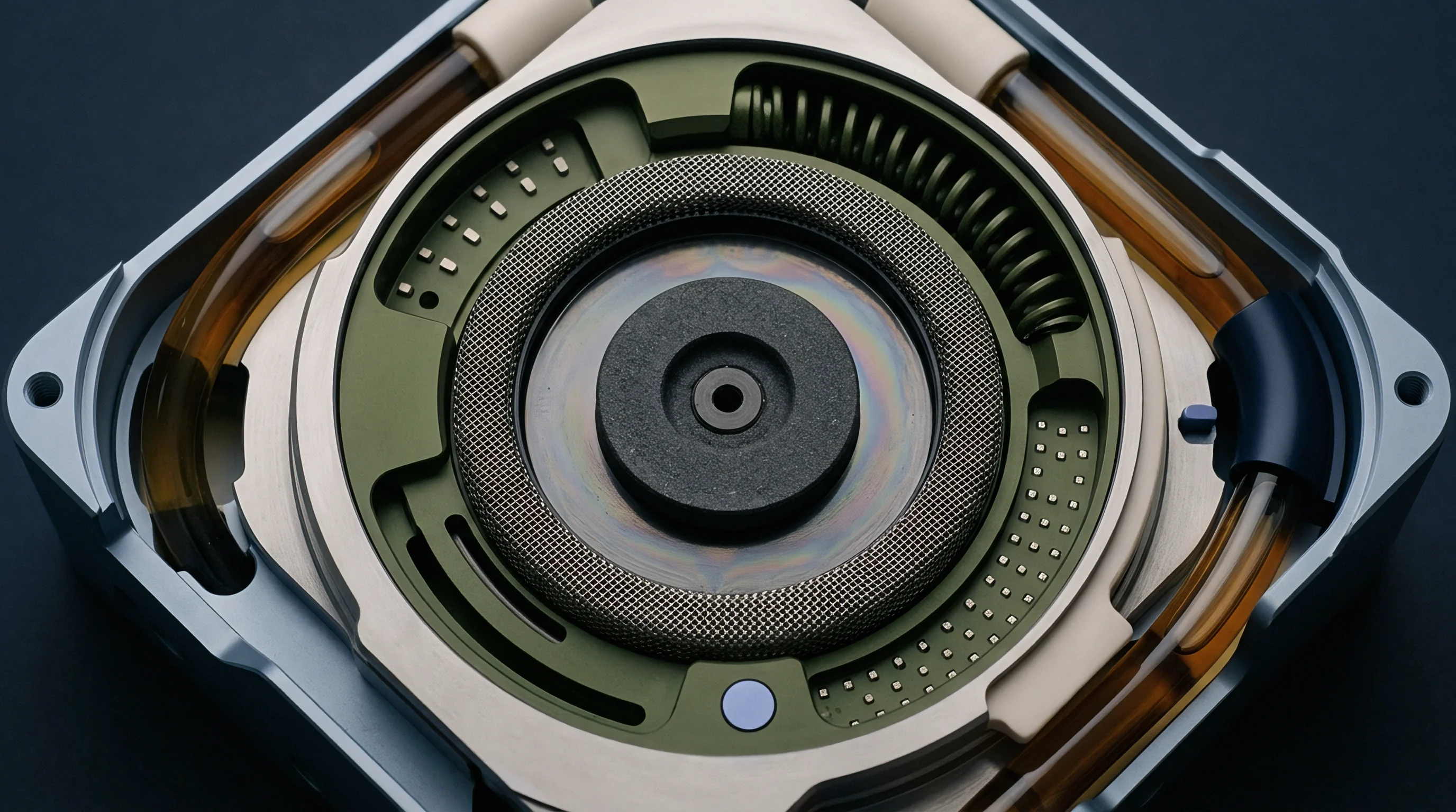
Feedthroughs are the primary mechanical weak point in three-electrode designs. Commercial pouch cells rely on aluminum laminate packaging ~ an outer polyamide layer, an aluminum barrier foil, and an inner heat-sealable cast polypropylene film. Running a third conductor through this perimeter creates another leak path.
While main tabs use wide polymer adhesive films to bond copper and aluminum to polypropylene, fine micro-reference wires require dedicated feedthrough collars capable of resisting solvent attack while holding vacuum hermeticity over thousands of cycles.

Will Reference Feedthrough Leakage Degrade Cell Vacuum?
Moisture entering through defective seals hydrolyzes lithium hexafluorophosphate in the electrolyte, generating hydrofluoric acid and phosphoryl gases that corrode the reference probe and degrade active cathode material. In pouch packaging, seal integrity dictates usable life: moisture ingress exceeding 10 micrograms per year accelerates reference drift enough to invalidate BMS feedback within months of deployment.
Commercial micro-reference feedthroughs draw on design practices from ultra-high vacuum systems and subsea cable penetrators, where ceramic-to-metal brazes or glass compression seals block ionic ingress under severe pressure differentials for decades. In prismatic battery headers, glass-to-metal seals or ethylene-tetrafluoroethylene compression grommets isolate the reference pin from the aluminum lid, with glass providing an impermeable barrier against dimethyl carbonate vapor. Pouch formats instead wrap the wire in micro-tubular polyimide sleeves or fluoropolymer jackets where it crosses the heat-sealed flange.
Pouch cells equipped with experimental reference feedthroughs show helium leak rates three orders of magnitude higher than standard dual-tab production units.
Integrating micro-references into automated winding or z-folding lines creates acute handling problems on the floor. Automated production machinery runs at web speeds above 800 millimeters per second; threading a 30-micron insulated probe between fast-moving separator sheets leads to frequent web tears, tracking errors, and uneven tension. Sourcing teams auditing prospective manufacturers check several specific quality metrics:
- Hermeticity verification data establishing helium mass spectrometer leak rates below 1.0e-8 mbar liters per second across all cell batches.
- Separator puncture resistance logs confirming that insertion of the reference wire does not reduce local mechanical burst strength below 4.5 Newtons per ASTM D3763.
- Reference alloy batch certificates detailing purity levels of baseline gold, bismuth, or lithium wire stock to four decimal places.
- Accelerated shelf storage records documenting reference drift after 60 days of storage at 60 degrees Celsius and 90 percent relative humidity.
Flexible polymer coatings are intended to cushion the probe and prevent mechanical damage, yet teardown inspections of rejected pilot cells reveal extensive separator indentation and localized active material stripping along the wire path.

Expense
Unit economics draw the line between laboratory diagnostics and pack-level deployment. Instrumenting every cell in an automotive or grid storage pack inflates the bill of materials and factory overhead: an 800-volt EV pack with 192 series-connected prismatic cells needs 192 isolated analog sensing channels to implement full closed-loop control. Between harness expansions, denser connectors, and dedicated front-end application-specific integrated circuits, electronics costs rise by 140 to 220 dollars per pack.
Cell-level integration also penalizes line yield. High-volume prismatic manufacturing lines operate with scrap rates between 1.2 and 2.5 percent, but introducing micro-reference hardware pushes pilot scrap to 5.0 to 8.5 percent through tab misalignments, leaky glass seals, and formation short circuits. That yield drop feeds directly into higher landed costs per kilowatt-hour, leaving procurement teams to balance upfront scrap against downstream warranty savings from suppressed lithium plating.
A financial model for a 10,000-unit deployment of 280 Ah lithium iron phosphate utility storage cells illustrates the trade-off. Comparing standard open-loop profiles against a closed-loop reference architecture that allows continuous 1.5C charging without plating yields the following lifecycle figures:
| Cost and Performance Parameter | Open-Loop Baseline Architecture | Closed-Loop Micro-Reference Architecture |
|---|---|---|
| Cell Purchase Cost per Unit | $82.00 | $94.50 |
| BMS Measurement Electronics per Cell | $1.80 | $4.20 |
| Pack Assembly Labor and Harness Overhead | $3.50 | $5.80 |
| Factory Incoming Scrap Rate (%) | 1.5% | 4.8% |
| Effective Initial Landed Cost per Usable Cell | $88.63 | $109.77 |
| Cycle Life to 80% SOH at 1.5C Cycling | 2,400 cycles | 4,900 cycles |
| Delivered Lifetime Energy per Cell (kWh) | 1,881 kWh | 3,841 kWh |
| Levelized Cell Cost per Delivered kWh | $0.0471 | $0.0286 |
| Warranty Reserve Allocation per Unit | $7.20 | $2.10 |
The higher initial capital outlay amortizes cleanly on assets with high utilization. While landed cell costs increase by nearly 24 percent, more than doubling cycle life under aggressive operation brings levelized cost per delivered kilowatt-hour down by 39 percent. For low-utilization equipment or systems charged slowly overnight, like residential backup units, the premium never pays back.
Viability rests squarely on heavy duty cycles: commercial delivery fleets, grid frequency regulation, and high-performance passenger vehicles subjected to routine fast charging.
Supply contracts for reference-equipped cells demand tight warranty definitions: supplier liability for premature capacity loss remains intact only if reference drift stays within 5 mV, whereas pack-level claims void entirely if diagnostic logs show the BMS allowed the anode to drop below zero volts against an unverified reference channel.