Solid State Reference Electrodes in Lithium Pouch Cells
Solid state reference electrodes isolate anode overpotentials in pouch cells to prevent fast-charge lithium plating despite severe geometric field distortions.

Probe
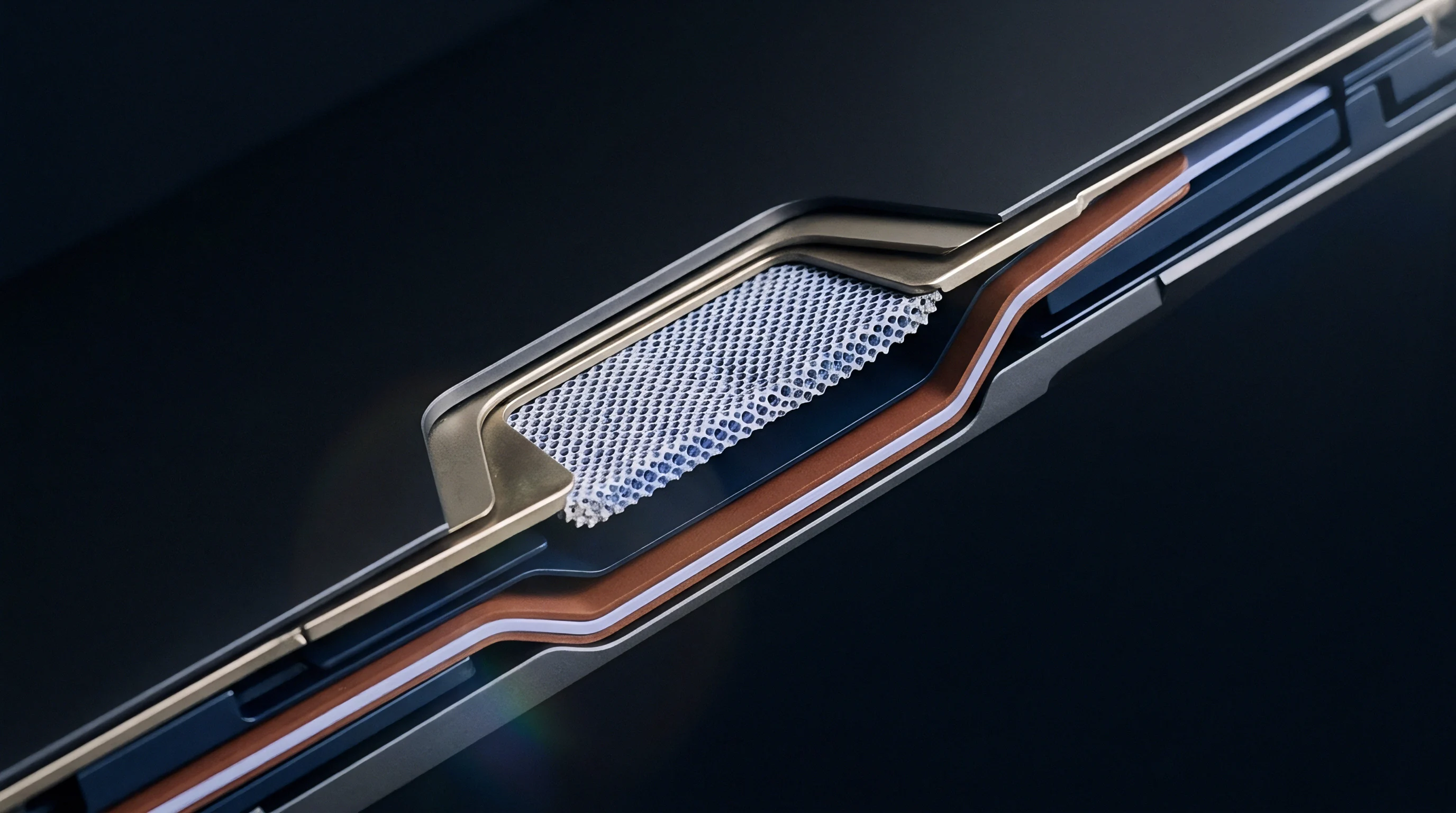
Placing an internal voltage sensor into a sealed lithium pouch cell exposes the separate polarization curves of the negative and positive electrode active materials during heavy cycling. Standard two-terminal cell measurements record only full-cell terminal potential, collapsing anode and cathode behaviors into a single composite differential. When an electric vehicle fast-charges at 3C or when an energy storage cell charges near zero degrees Celsius, the graphite negative electrode potential drops toward zero volts relative to metallic lithium.
Lithium metal deposits as dendrites once this potential drops below zero volts versus lithium. A solid state reference electrode functions as an independent thermodynamic bench inside the cell stack, allowing direct observation of the graphite overpotential without shorting the surrounding separator layers.
Two-terminal instrumentation cannot isolate which electrode drives cell impedance growth over extended cycling. The introduction of an extra sensing terminal isolates the individual contributions of cathode transition-metal degradation, electrolyte reduction, and anode interface thickening.

Sandwich Geometry and Pouch Packaging
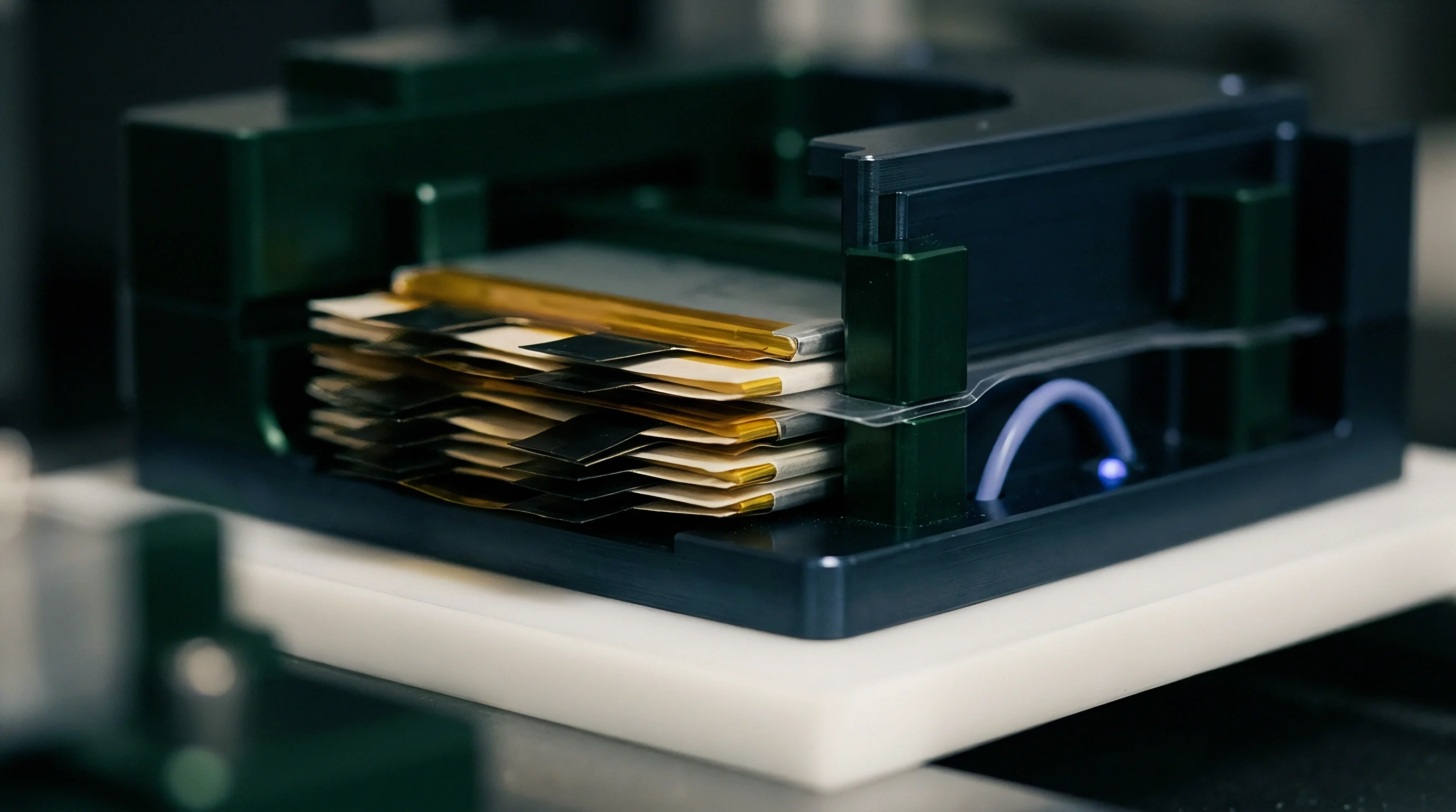
Mechanical integration inside a commercial cell demands sub-millimeter thickness profiles to avoid creating mechanical stress risers across the jellyroll or z-folded stack. Insertion between the separator folds introduces local pressure peaks during cell expansion. Standard pouch cell manufacturing compresses alternating layers of cathode, separator, and anode under 0.2 to 0.8 MPa of uniform stack pressure.
If the reference sensor exceeds fifty micrometers in total thickness, local pressure concentration displaces liquid electrolyte, pinches the porous separator, and accelerates localized mechanical tearing during cell swelling.
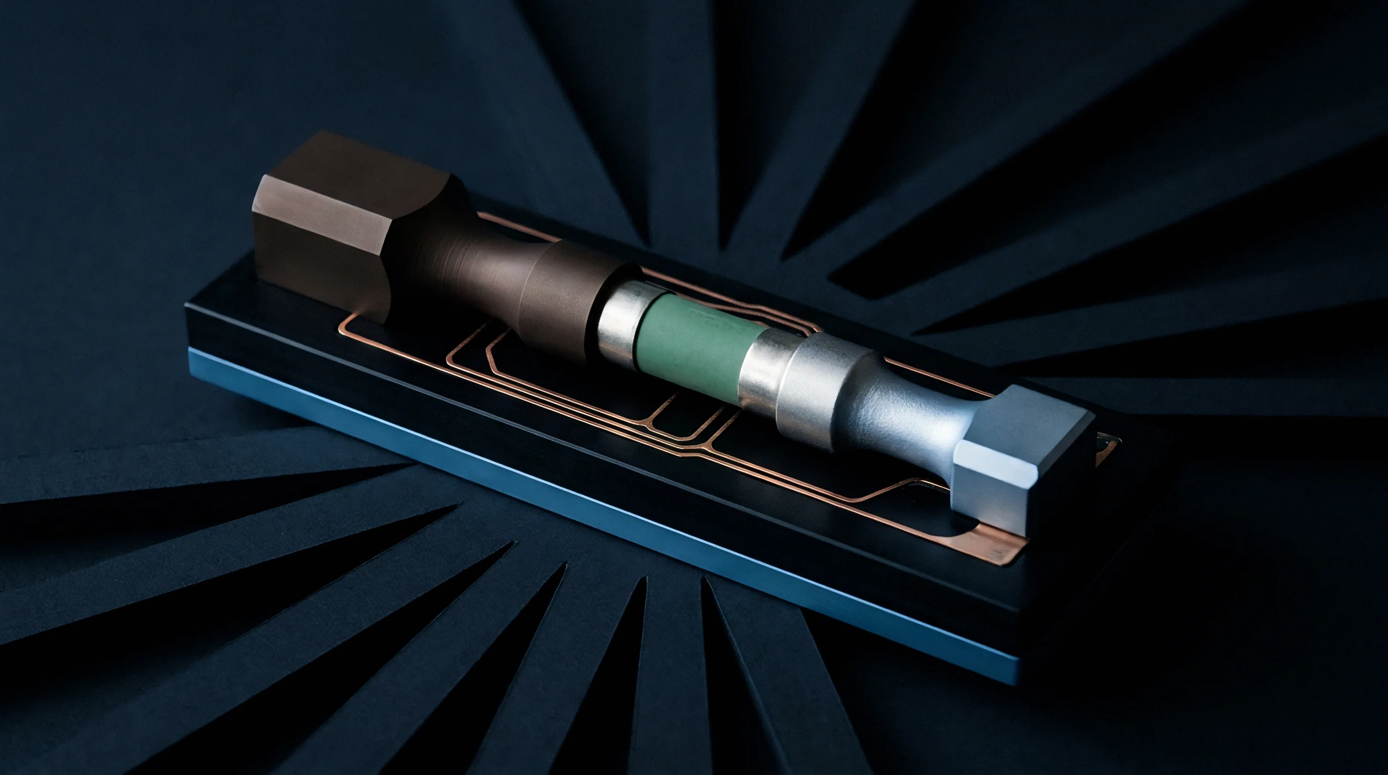
Wire-based solid state reference sensors utilize insulated micro-filaments: gold, copper, platinum, or tungsten cores coated with a pinhole-free polyimide or fluoropolymer sheath, exposing only the active sensing tip. The active tip sits centrally within the active electrode area, positioned precisely between two separator membranes. Positioning the sensor at the stack periphery creates severe fringing field artifacts, as the current flux density at electrode cut edges differs substantially from the uniform ionic flux across the central active area.
| Sensor Substrate Type | Total Core Diameter | Insulation Layer Material | Active Tip Geometry | Permissible Stack Thickness |
|---|---|---|---|---|
| Tungsten Micro-Wire | 25 micrometers | Polyimide resin (5 micrometers) | Planar shear cut | Under 35 micrometers |
| Lithium-Alloyed Gold Wire | 50 micrometers | PTFE shrink-sleeve (10 micrometers) | Exposed bevel point | Under 70 micrometers |
| Perovskite-Coated Platinum | 15 micrometers | Alumina atomic vapor film | Spherical micro-bead | Under 25 micrometers |
| Titanate Film on Polyimide | 12 micrometers | Polyimide carrier substrate | Screen-printed pad | Under 20 micrometers |
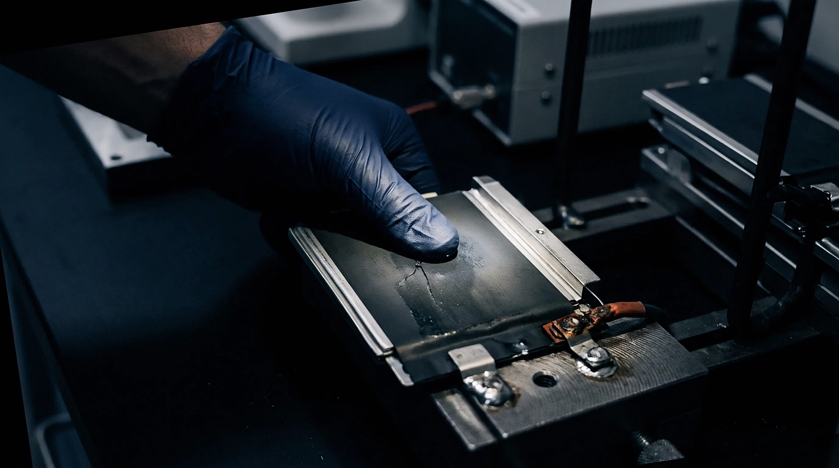
Tab feedthrough execution determines pouch hermetic integrity over time. The solid state reference wire must exit the aluminum laminate envelope without permitting moisture ingress or electrolyte leakage. Water ingress rates above 5 ppm per year initiate rapid lithium hexafluorophosphate hydrolysis, producing hydrofluoric acid that attacks both active materials and the reference tip itself.
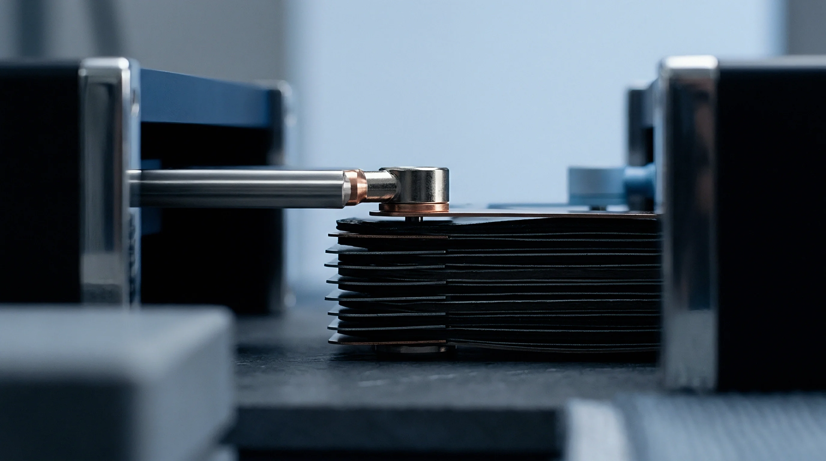
A dedicated reference tab incorporates modified polypropylene sealant film identical to the polymer layer of the pouch casing. Ultrasonic welding or micro-resistance spot welding joins the sensor filament to an external nickel tab, which passes through the pouch perimeter seal under standard heat-sealing conditions: 190 degrees Celsius at 0.4 MPa for three seconds.
The reference sensor layer thickness must remain below forty micrometers to preserve uniform mechanical compression across the cell stack.
Crush the separator during pouch heat sealing or stack calendering, and the internal reference wire bridges the graphite anode directly to the cathode, triggering irreversible internal short-circuit heating that incinerates the test channel.

Phase
Thermodynamic stability governs reference electrode material selection. An ideal reference material establishes a constant equilibrium potential unaffected by changes in local lithium-ion concentration, solvent dielectric properties, or micro-current drain from high-input-impedance electrometers. Liquid lithium metal electrodes provide a well-defined potential of zero volts, yet pure metallic lithium melts at 180 degrees Celsius, reacts vigorously with alkyl carbonate solvents, and undergoes rapid morphological disintegration under prolonged immersion.
When an insulated gold micro-wire contacts the electrolyte within a lithium cell, an applied in-situ lithiation pulse drives lithium ions into the gold lattice, creating intermetallic gold-lithium phases. The alpha-phase solid solution shifts into the biphasic LiAu plus Li3Au regime, exhibiting a flat open-circuit potential plateau near 0.32 volts relative to pure lithium. The potential remains constant as long as the reference alloy remains inside this two-phase coexistence zone.
Thermodynamic Plateaus in Two Phase Alloys
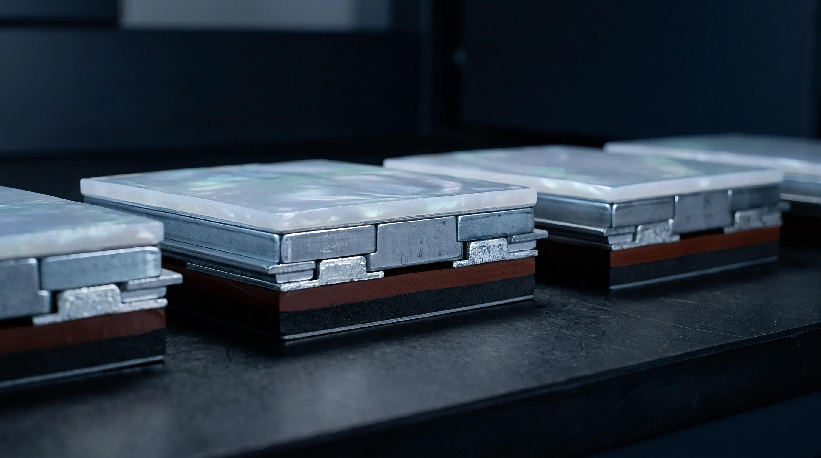
Lithium iron phosphate and lithium titanate compounds function as reliable insertion-type reference materials. Both materials rely on two-phase transition mechanics that fix the chemical potential of lithium across a broad composition range.
- Lithium Titanate Systems generate a flat potential plateau at 1.55 volts versus lithium metal through a two-phase equilibrium between spinel Li4Ti5O12 and rock-salt Li7Ti5O12 structures.
- Lithium Iron Phosphate maintains an invariant potential of 3.42 volts against metallic lithium across state-of-charge values from ten percent to ninety percent via the olivine phase transformation.
- Lithium Gold Intermetallics produce stable reference plateaus between 0.31 and 0.33 volts through reversible transitions between LiAu and Li2Au crystal structures.
- Lithium Bismuth Alloys deliver a flat reference response at 0.81 volts through formation of the intermetallic Li3Bi lattice during pre-conditioning currents.
Solvent reduction challenges naked metal wires. Pure carbonate electrolytes containing ethyl methyl carbonate, ethylene carbonate, and dimethyl carbonate undergo reduction at potentials below 0.8 volts versus lithium, forming a solid electrolyte interphase directly across the sensing surface. A solid state reference electrode avoids continuous dynamic interphase modification by utilizing chemically stable inorganic solid electrolytes as ion-selective buffer membranes.
Coating the reference wire tip with a thin layer of lithium phosphorus oxynitride, lithium aluminum titanium phosphate, or garnet-type lithium lanthanum zirconium oxide creates a dense physical barrier. This ceramic mantle conducts lithium ions selectively while blocking electrons and bulky solvated carbonate complexes from contacting the reference core. Electronic conductivity in the coating must remain below 10 to the power of negative ten Siemens per centimeter to prevent self-discharge of the reference active material.
A biphasic equilibrium fixes the open-circuit voltage across wide stoichiometry swings.
A reference material showing continuous solid-solution behavior produces a drifting potential signal during cell cycling.


Distortion
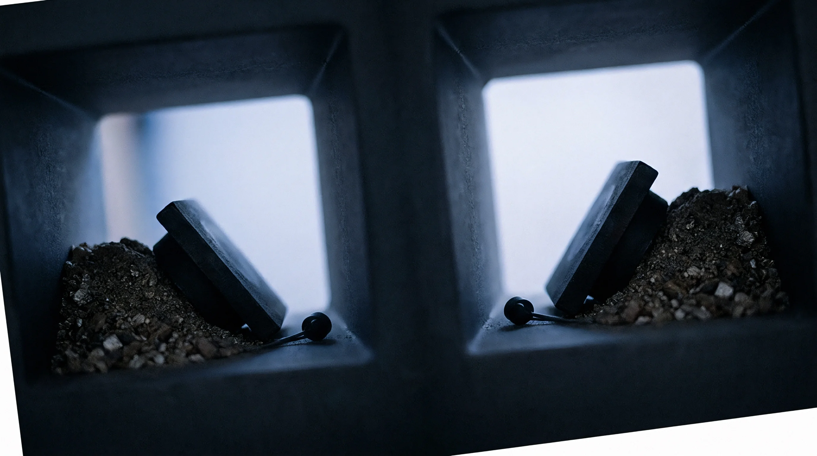
Introducing an extra conducting element into the narrow gap between pouch cell electrodes disrupts the uniform electrostatic potential distribution. Under heavy load, lithium-ion current flows perpendicular to the electrode surfaces across an electrolyte-saturated separator typically fifteen to twenty micrometers thick. The insertion of a physical sensor creates an excluded volume where ionic transport cannot occur, forcing current lines to bend around the probe.
This geometric shadow effect alters the local current density at the adjacent graphite surface, inducing premature local lithium plating immediately underneath the reference tip while the surrounding electrode remains within safe operating limits.
When current lines deflect around an insulated reference wire, local overpotentials deviate significantly from the true 1D planar behavior modeled in classical Newman battery equations. Finite element modeling of a 50-micrometer insulated wire placed in a 20-micrometer separator shows local ionic current density spikes exceeding 250 percent of the average nominal current density at the sensor edges. This concentration accelerates local degradation, skewing long-term life data gathered from that specific location.
Where Does Electric Field Distortion Induce Measurement Error?
Potential gradients across the liquid electrolyte introduce severe ohmic drop artifacts into the reference signal. The measured potential between the reference electrode and the working electrode represents the sum of the true interfacial potential, the solid-state charge-transfer overpotential, and the uncompensated electrolyte resistance between the probe tip and the electrode interface. Because the reference sensor cannot sit precisely within the infinitesimal double layer, it registers a fraction of the macroscopic electric field driving the primary current between anode and cathode.
| Discharge Rate | Electrolyte Conductivity | Sensor-to-Anode Offset | Uncompensated Resistance | Induced Ohmic Voltage Error |
|---|---|---|---|---|
| 0.5C (1.5 A) | 10.5 mS/cm | 5 micrometers | 0.12 ohms | 1.8 millivolts |
| 1.0C (3.0 A) | 10.5 mS/cm | 5 micrometers | 0.12 ohms | 3.6 millivolts |
| 3.0C (9.0 A) | 8.2 mS/cm (at 10 deg C) | 8 micrometers | 0.28 ohms | 25.2 millivolts |
| 5.0C (15.0 A) | 6.1 mS/cm (at 0 deg C) | 12 micrometers | 0.54 ohms | 81.0 millivolts |
An induced error of eighty millivolts obscures the onset of low-temperature lithium plating entirely. During 5C fast-charging protocols, an anode operating at positive thirty millivolts true potential appears to operate at negative fifty millivolts if the reference sensor sits biased toward the cathode side of the separator. Conversely, biasing the sensor toward the anode suppresses early detection of dendrite formation, generating false-positive stability margins during battery management software calibration.
Pouch cells breathe during charge and discharge: graphite expands by approximately ten to twelve percent during full lithiation, while silicon-graphite composite anodes expand by twenty to forty percent depending on silicon content. This continuous dimensional pulsation shifts the mechanical position of the reference probe relative to the active surfaces. A sensor calibrated at zero percent state of charge experiences physical translation and altered contact pressures as the cell approaches full charge, changing the geometric weighting factor of the potential field.
At five C-rate charging in cold conditions, an uncompensated electrolyte resistance of half an ohm generates over eighty millivolts of spurious potential shift.
Unexpected negative overpotential readings can stem from micro-scale geometric misalignment inside the separator envelope rather than active lithium metal plating.

Drift
Sustaining absolute measurement stability across hundreds of continuous cycles represents the primary operational barrier for in-situ reference sensors. Unlike standard two-terminal cells where small parasitic currents redistribute charge within the active materials, reference electrodes connect to high-impedance electrometers drawing continuous input bias currents between one picoampere and one nanoampere. Over three to six months of testing, even a ten-picoampere leakage current drains micro-coulombs of charge from a sub-milligram reference alloy bead, systematically shifting its stoichiometry off the flat thermodynamic plateau.
If the electrometer input impedance drops below 10 to the power of twelve ohms, continuous micro-drain depletes the reference alloy reservoir rapidly. When the composition leaves the two-phase equilibrium, the open-circuit voltage begins to track the steep solid-solution slopes of single-phase regimes, generating progressive baseline drift of ten to fifty millivolts per week.

Will Solid Electrolyte Coatings Suppress Lithium Depletion?
Chemical crossover inside the liquid electrolyte represents an independent source of reference baseline decay. In commercial lithium-ion pouch cells operating above 4.2 volts, manganese, cobalt, and nickel ions dissolve from cathode active materials into the alkyl carbonate solvent. These dissolved transition metal cations migrate across the separator toward the anode.
When dissolved divalent manganese ions encounter an unprotected reference alloy or titanate tip, they undergo spontaneous electrochemical displacement, depositing elemental manganese on the reference surface and consuming active lithium.
- Electrolyte Infiltration Phase occurs as carbonate solvents wet the porous grain boundaries of the inorganic ceramic coating within the first twenty-four hours of cell activation.
- Solvent Reduction Transition drives initial protective passivating film growth across grain boundary imperfections, increasing sensor interfacial impedance from hundreds of ohms to tens of thousands of ohms.
- Transition Metal Adsorption introduces dissolved nickel and manganese species into the outer reference boundary, catalyzing continuous electrolyte oxidation and reduction reactions.
- Plateau Exhaustion Event marks the final thermodynamic failure point when parasitic charge transfer completely depletes the two-phase alloy reserve, resulting in erratic, rate-dependent sensor drift.
Pouch cell degradation tracking requires reference baseline stability tighter than five millivolts over one thousand hours of operation. If reference drift exceeds this threshold, automated fast-charge software algorithms miscalculate the anode plating overpotential threshold, either throttling charge acceptance unnecessarily or allowing dendrites to pierce the separator.
A single nanoampere of electrometer bias current exhausts the thermodynamic two-phase reservoir of a micro-reference bead within two hundred hours of continuous measurement.
How can factory qualification protocols confirm that a reference electrode maintains its potential baseline when physical extraction and post-mortem titration destroy the very ceramic interface under examination?
Margin
Industrial deployment of reference-instrumented pouch cells is confined to qualification lots and battery management system calibration programs. A production cell costs between sixty and ninety dollars per kilowatt-hour at current factory gate pricing. Fabricating, inserting, and validating a three-electrode pouch cell increases the unit cost by a factor of eight to fifteen.
Manual stack placement, specialized tab sealing, and prolonged pre-lithiation protocols restrict throughput to pilot-line volumes.
Inadvertent reverse biasing of a reference electrode or reference tab during pre-conditioning strips copper current collectors above three volts or destroys thin-film reference substrates. To validate fast-charge envelopes, quality assurance departments subject instrumented qualification cells to aggressive step-charging regimes, mapping the exact boundary where anode overpotential crosses zero millivolts across temperatures from minus twenty to plus forty-five degrees Celsius.

Cell Qualification and Fast Charge Boundary Limits
A reference-equipped pouch cell establishes the true maximum safe current envelope for commercial battery management firmware. Cell specification sheets frequently claim ten-minute charging capabilities from ten to eighty percent state of charge. Independent verification on an instrumented cell reveals whether the graphite anode potential dips into the negative region during these charging pulses.
| Ambient Temperature | Tested Charge Rate | Anode Potential versus Li/Li+ | Plating Risk Assessment | Firmware Limit Action |
|---|---|---|---|---|
| 45 degrees Celsius | 3.0C (constant current) | +42 millivolts | Zero metallic plating observed | Permit full 3.0C current rate |
| 25 degrees Celsius | 3.0C (constant current) | +8 millivolts | Boundary proximity margin critical | Throttle to 2.2C above 60% SOC |
| 10 degrees Celsius | 1.5C (constant current) | -14 millivolts | Active dendritic plating underway | Clamp maximum current to 0.8C |
| 0 degrees Celsius | 1.0C (constant current) | -38 millivolts | Severe plating and rapid capacity fade | Enforce 0.2C trickle pre-heat |
When drafting supply agreements and technical annexes for custom three-electrode validation batches, testing engineering teams must explicitly define measurement tolerances, input impedance baselines, and post-testing teardown verification. Standard warranty clauses do not cover internal instrumentation failures caused by handling damage or excessive clamping force during bench mounting.
UN 38.3 transport certification regulations classify custom three-electrode test cells as non-standard prototypes, mandating dedicated shipping declarations and specialized crating prior to transit.
Under international test specification IEC 62660-1 Section 6.2, supplier performance guarantees remain legally binding only when multi-electrode cell data can be correlated directly with standard production two-terminal impedance baselines across identical thermal envelopes.