Moisture Control from Electrolyte Fill to Export Container
Electrode vacuum baking below 15 ppm residual water prevents hydrofluoric acid formation during electrolyte filling, preserving cell cycle life and landed margin.
Dewpoint
Electrode rolls retain residual moisture trapped deep inside microscopic cathode pores and organic binder networks. While convective drying removes unbound surface water quickly, capillary-bound liquid and adsorbed hydroxyl groups remain locked within the active material. Lithium nickel manganese cobalt oxide (NCM) structures bind surface moisture through polar interactions, whereas lithium iron phosphate (LFP) particles retain water inside porous carbon agglomerates.
Eliminating this moisture requires thorough thermal extraction prior to cell assembly, as any residual water entering the cell cavity causes immediate electrochemical degradation upon contacting non-aqueous electrolyte salts.
Cell manufacturing plants track environmental moisture using frost point metrics inside controlled dry rooms. Standard atmospheric air with ten thousand parts per million of water vapor can ruin exposed electrode coatings within minutes. Air handling systems constantly adjust vapor pressure differentials to keep ambient humidity below strict limits.
Water molecules adsorb rapidly onto high-surface-area materials: graphite anodes pull moisture into interstitial layer edges, while nickel-rich cathodes undergo spontaneous surface phase changes when exposed to humid air.
Unchecked moisture inside the cell leads directly to accelerated capacity fade, gassing, and early battery failure.
Vacuum Baking Thermal Profiles
Electrode bobbins undergo multi-stage heating in convective vacuum chambers to drive off absorbed liquid. Slit rolls of cathode and anode webs are stacked on heated shelves inside sealed vacuum ovens. Under vacuum, heat transfer relies primarily on conductive contact between the heated shelf and the aluminum or copper foil core, supplemented by radiant heat from the oven walls.
Periodic dry nitrogen purge pulses break the vacuum, creating convective micro-currents that sweep vaporized moisture out of the tightly wound roll cores.
Heating schedules use controlled temperature ramps to protect sensitive organic polymers. Polyvinylidene fluoride (PVDF) binder networks experience structural relaxation and migration if heating exceeds two degrees Celsius per minute. Sudden solvent vaporization generates internal steam pressure gradients that break binder bridges between active cathode particles and conductive carbon additives, leading to foil delamination during unwinding.
Target temperatures depend on electrode chemistry and binder formulations. Carboxymethyl cellulose (CMC) and styrene-butadiene rubber (SBR) anode coatings can withstand up to one hundred and ten degrees Celsius before the elastomer network degrades. In contrast, PVDF-based cathode coatings tolerate up to one hundred and thirty degrees Celsius under vacuum pressures below fifty Pascals.
Residence times in industrial ovens range from twelve to twenty-four hours, depending on roll width, coating thickness, and winding tightness.
| Electrode Chemistry | Binder System | Bake Temp (°C) | Vacuum Pressure (Pa) | Residence Time (hr) | Target Water (ppm) |
|---|---|---|---|---|---|
| LiNi0.8Mn0.1Co0.1O2 (NCM811) | PVDF / NMP | 120 | 20 | 18 | 150 |
| LiFePO4 (LFP) | PVDF / NMP | 130 | 10 | 24 | 200 |
| Graphite / Silicon Composite | CMC / SBR Water-based | 105 | 50 | 14 | 300 |
| LiNi0.6Mn0.2Co0.2O2 (NCM622) | PVDF / NMP | 125 | 30 | 16 | 200 |
Continuous roll-to-roll vacuum drying systems provide an alternative to batch bobbin ovens. Precision web machinery pulls unwound electrode strips through multi-zone heating tunnels fitted with active vacuum locks. Infrared elements deliver heat directly into the passing coating, evaporating moisture in seconds.
Continuous drying avoids the steep thermal gradients typical of large bobbin rolls, where core layers often lag outer layers by several hours during heating.
Karl Fischer Moisture Titration Parameters
Measuring internal moisture relies on high-temperature gas extraction paired with coulometric Karl Fischer titration. Technicians collect representative punch samples from dried electrode rolls inside nitrogen gloveboxes. Each sample is sealed in a glass vial and placed into a furnace module.
Dry nitrogen carrier gas sweeps vaporized volatiles from the heated vial into the titration cell containing an iodine reagent.
Extraction temperatures directly affect measurement accuracy. Heating cathode samples to one hundred and seventy degrees Celsius releases surface and capillary-bound water without breaking down the transition metal oxide crystal structure. Heating past two hundred degrees Celsius, however, decomposes residual lithium carbonate surface impurities, generating reaction water that artificially inflates moisture readings.
Anode samples require heating to two hundred and twenty degrees Celsius to liberate water trapped within CMC polymer chains.
Cathode webs dried below 150 ppm water content at 120°C under 50 Pa vacuum maintain nominal discharge capacity through 1,500 continuous cycles at 1C discharge rate.
Titration cell drift rates define the instrument’s lower detection limit. Carrier gas flow must stay at exactly one hundred milliliters per minute to avoid pressure fluctuations inside the vessel. Background drift exceeding five micrograms of water per minute signals line contamination or reagent exhaustion.
Running blank dry vial tests before sample runs allows technicians to subtract baseline drift from final moisture calculations.
Coulometric titrators convert the electrical current required to regenerate iodine into total water weight. By Faraday’s law, one mole of iodine reacts with one mole of water, establishing a direct stoichiometric relationship between current and moisture mass. Dividing this value by dry sample weight gives the residual water concentration in parts per million.
Any electrode lot exceeding specified moisture thresholds is rejected before cell assembly.
Dry Room Air Conditioning Infrastructure
Maintaining ultra-low vapor pressures requires dual-stage desiccant rotor systems combined with cooling coils. Incoming outside air first passes through cooling coils to condense bulk moisture, lowering the dew point to ten degrees Celsius. The pre-cooled air then enters the desiccant dehumidification system.
Dual-wheel systems use a primary silica gel rotor followed by a secondary molecular sieve rotor to strip remaining moisture down to deep sub-zero frost points.
Molecular sieve rotors use synthetic zeolites with uniform three-angstrom pores. Water molecules, with a kinetic diameter of two point six angstroms, enter the zeolite structure and bind to sodium ions, while larger nitrogen and oxygen molecules pass through unobstructed. A continuous reactivation airstream heated to one hundred and eighty degrees Celsius strips trapped moisture from the rotating wheel segment and vents it outside the building.
Air distribution networks maintain positive static pressure gradients across the facility. Dry room enclosures operate at twenty to fifty Pascals above surrounding buffer zones, preventing ambient air from infiltrating door seals, joints, or material pass-throughs. Air change rates in electrode assembly areas reach eighty changes per hour to sweep away moisture introduced by workers and machinery.
Because small humidity spikes can ruin exposed materials, dry room air quality is continuously monitored at multiple sensor locations.
Personnel are the primary source of moisture in dry rooms. A fully gowned operator generates three to five grams of water vapor per hour through respiration and transpiration, even in protective suits. Facilities restrict the number of technicians allowed inside active zones and enforce strict airlock protocols.
For manual maintenance in ultra-low dew point areas, technicians wear full-face respirators supplied with dry air or closed-loop breathing gear.
- Verify dry room dew point sensors indicate below minus fifty degrees Celsius at all ambient sampling locations.
- Calibrate coulometric Karl Fischer titration instruments using standard water samples to confirm measurement drift stays under three micrograms per minute.
- Extract three punch specimens from the inner core, middle wrap, and outer layer of each vacuum-baked electrode roll inside a sealed glovebox.
- Execute thermal gas extraction titration at one hundred and seventy degrees Celsius for cathode samples and two hundred and twenty degrees Celsius for anode samples.
- Log moisture values into the execution system to automatically release compliant electrode rolls to the slit-winding production line.
Sensors distributed throughout the dry room track ambient frost points. Chilled mirror hygrometers serve as primary standards by optically detecting the exact temperature at which dew or frost condenses on a mirror surface. Polymer capacitive sensors provide faster response for local monitoring, though optical mirror systems remain necessary for high-accuracy reference to eliminate drift over long campaigns.
Extending bake cycles past the point of diminishing returns weakens binder cohesion long before removing the last traces of moisture.
Hydrolysis
Filling dry cell cavities with non-aqueous electrolyte initiates destructive side reactions if ambient water vapor remains. Commercial battery electrolytes use lithium hexafluorophosphate salt dissolved in organic carbonate solvents like ethylene carbonate, dimethyl carbonate, and ethyl methyl carbonate. In solution, lithium hexafluorophosphate exists in equilibrium with lithium fluoride and phosphorus pentafluoride.
Trace water reacts instantly with phosphorus pentafluoride, shifting the equilibrium and producing hydrofluoric acid.
When moisture mixes with dissolved lithium salts, it triggers runaway acid generation inside the cell.
Hydrofluoric acid formation is self-catalyzing. One mole of water reacts with one mole of lithium hexafluorophosphate to produce one mole of hydrofluoric acid, one mole of lithium fluoride, and one mole of phosphoryl fluoride. Phosphoryl fluoride then reacts with additional trace water, generating two more moles of hydrofluoric acid alongside difluorophosphoric acid.
This cycle consumes electrolyte solvents and produces acidic byproducts until all water is exhausted.

Acidic Degradation Pathways
Acidic compounds attack active cathode materials, leaching transition metal ions like manganese and nickel from the oxide lattice. Hydrofluoric acid strips cations from particle surfaces, degrading the structural integrity of NCM and LFP crystal frameworks. During initial formation cycles, these dissolved metal ions migrate through the porous polymeric separator under electric fields and concentration gradients.
Once across the separator, metal cations deposit onto the graphite anode. These metallic deposits act as catalytic sites that break down the protective solid electrolyte interphase (SEI) layer. As the SEI degrades, the cell continuously consumes active lithium from the electrolyte to rebuild the passivation film, leading to capacity loss and rapid impedance growth.
| Initial Water (ppm) | HF Generation (ppm, 24h) | Transition Metal Dissolution (ppm) | 500-Cycle Retention (%) | Gas Volume (mL/Ah) |
|---|---|---|---|---|
| 10 | 12 | < 0.5 | 94.2 | 0.05 |
| 30 | 45 | 2.1 | 89.6 | 0.22 |
| 50 | 88 | 6.8 | 82.1 | 0.58 |
| 100 | 195 | 18.4 | 68.3 | 1.45 |
| 200 | 420 | 45.2 | 41.0 | 3.80 |
Acidic attack fundamentally damages active electrode structures and shortens operational lifespan.
Electrolyte hydrolysis produces significant quantities of gas. Phosphoryl fluoride and difluorophosphoric acid react with organic carbonates to form volatile alkyl fluorophosphates, carbon dioxide, and gaseous ethers. This gas buildup swells pouch cells and increases internal pressure in prismatic cases.
The resulting physical separation of electrode stacks disrupts uniform lithium-ion transport.
Hydrolysis also causes solid lithium fluoride to precipitate. Suspended lithium fluoride particles clog the microscopic pores of polyolefin separators, hindering ion movement between electrodes. This pore clogging raises bulk electrolyte resistance, causing steep increases in charge-transfer resistance during impedance testing.
Degassing Operations during Formation
Initial formation cycles vent volatile gases into designated cell header pockets. Pouch cells use an extended temporary gas bag along the top seal. Generated gases collect inside this pocket, drawing harmful byproducts away from the active electrode stack.
Automated machinery then cuts off the gas pocket and performs final vacuum sealing in a dry enclosure.
Side-cutting equipment pierces the gas bag under active vacuum. A blade cuts the laminate while suction cups pull the pouch walls apart to evacuate carbon dioxide, hydrofluoric acid vapor, and solvent fumes. Heated sealing jaws then clamp down below the cut line to create the final hermetic seal before trimming off the spent bag.
Contractual electrolyte purity clauses specifying maximum 10 ppm water content transfer all warranty costs to the salt supplier when high-temperature storage gassing exceeds five percent volume growth.
Vacuum levels during final sealing control the remaining gas volume inside the cell. Too strong a vacuum boils off volatile, low-boiling solvents like dimethyl carbonate, altering the electrolyte ratio. Insufficient vacuum leaves pockets of gas trapped between electrode sheets, creating localized high-current spots that cause lithium plating during fast charging.
Prismatic hard-case cells rely on mechanical vent valves or temporary fill plugs during formation. Byproduct gases vent through the fill port while cells sit in temperature-controlled trays. Automated arms then place temporary rubber plugs, transfer cells to vacuum chambers to pull headspace air, and press permanent steel sealing balls into the fill ports.
Electrolyte barrels left in unconditioned staging areas show moisture absorption rates exceeding forty parts per million of water within forty-eight hours of opening.
Electrolyte dispensing systems require helium-purged transfer lines. Stainless steel supply piping undergoes vacuum baking and continuous dry argon sweeping before commissioning. Storage drums connect to dispensing units via double-walled couplings with nitrogen purge shrouds, ensuring chemical transfer happens with zero atmospheric contact.
- Anode Delamination occurs when hydrolyzed acidic electrolyte breaks down aqueous carboxymethyl cellulose binder networks, stripping graphite particles from copper current collector foils.
- Cathode Surface Phase Transformation develops as hydrofluoric acid extracts lithium ions from layered structures, forming inactive rock-salt phase layers on oxide particle surfaces.
- Gas Pocket Formation occurs when carbon dioxide and volatile fluorophosphates accumulate between electrode layers, creating non-conductive gaps that trigger localized lithium plating.
- Separator Pore Blocking happens as insoluble lithium fluoride salt precipitates out of degraded electrolyte, clogging sub-micron polyolefin pores and restricting ionic conductivity.
- Impedance Growth Spikes develop as degraded SEI components and dissolved transition metals continuously rebuild resistive interface layers on anode particle surfaces.
Acid concentration checks verify incoming electrolyte purity. Quality control technicians sample bulk shipments using automated potentiometric titration with basic reagents. Shipments with hydrofluoric acid levels above twenty parts per million are rejected to protect downstream filling equipment from contamination.
Gas expansion deforms pouch cell walls and compromises internal stack alignment.
Electrolyte breakdown raises cell resistance and degrades discharge efficiency.
Unconditioned filling room air degraded an entire pre-production cell lot in one incident, resulting in twenty-eight thousand dollars in replacement freight and retesting costs.
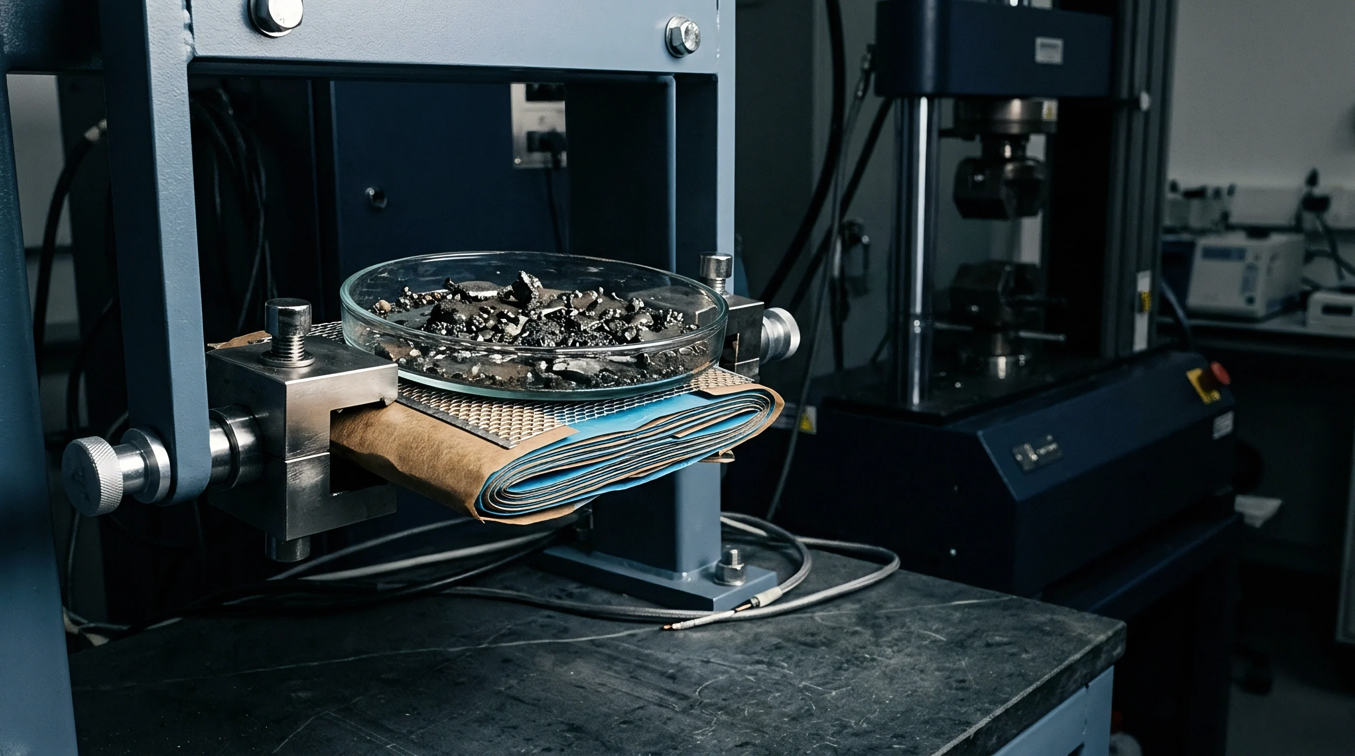

Foil
Long-term containment depends on barrier materials that isolate internal chemistry from ambient moisture. Flexible pouch cells use multi-layer aluminum laminate foils designed for water vapor barrier performance and puncture resistance. Prismatic cells use deep-drawn aluminum alloy cans laser-welded to top cover plates.
Both approaches demand defect-free perimeter seals to survive operating lifespans over ten years.
Aluminum laminates bond functional polymer films to a central metal foil core. The outer layer is a biaxially oriented nylon film that provides tensile strength and abrasion resistance. The core is a forty- to fifty-micrometer annealed aluminum foil that blocks water vapor, oxygen, and light.
The inner layer uses cast or acid-modified polypropylene, forming the heat-sealable chemical barrier.

Impulse Thermal Sealing Mechanics
Sealing pouch cell perimeters requires controlled heat and pressure. Heated jaws squeeze the laminate edges, bringing the inner polypropylene layers above their melting point of one hundred and sixty-five degrees Celsius. Under pressure, molten polymer chains intermingle and fuse into a continuous solid bond as they cool.
Jaw temperature determines melt quality. Insufficient heat leaves un-melted boundary lines that form microscopic channels, allowing moisture to diffuse into the cell over time. Overheating forces molten polymer out of the joint area entirely, thinning the protective layer and exposing the raw aluminum foil to corrosive electrolyte.
Maintaining uniform pressure along the entire length of the sealing jaws is essential to avoid localized defects.
Uniform pressure prevents localized thinning of the inner polymer layer. Load cells in the sealing equipment measure force distribution across the jaws. Over continuous production runs, thermal expansion can warp jaw flatness, concentrating pressure at the edges while leaving center regions under-sealed.
| Parameter Metric | Under-Sealed Window | Nominal Process Window | Over-Sealed Window |
|---|---|---|---|
| Sealing Temperature (°C) | < 175 | 185 – 195 | > 210 |
| Dwell Time (seconds) | < 2.0 | 3.5 – 4.5 | > 6.0 |
| Sealing Pressure (MPa) | < 0.3 | 0.45 – 0.55 | > 0.7 |
| Polypropylene Thickness Retention (%) | > 95 (no fusion) | 70 – 80 | < 40 (squeeze out) |
| Moisture Vapor Transmission (g/m²/day) | > 1.0 × 10⁻² | < 1.0 × 10⁻⁵ | > 5.0 × 10⁻³ |
Dwell time works in tandem with temperature and pressure settings. Heat takes time to conduct through the outer nylon and aluminum layers to melt the inner polypropylene. Industrial sealing profiles typically use dwell times between three and five seconds, balancing cycle time against complete polymer bonding.
Mechanical strength testing verifies seal quality. Technicians cut fifteen-millimeter wide test strips across the seal and run T-peel tests on tensile testers. Acceptable seals show peel forces above thirty-five Newtons per fifteen millimeters, failing through cohesive tearing of the polypropylene rather than layer separation.
Helium Leak Detection Protocols
Prismatic cases are leak-tested in vacuum chambers using helium mass spectrometry. Before final sealing, the cell receives three bar of pure helium through its fill port. Pumps evacuate the test chamber to one Pascal, drawing any escaping helium through the mass spectrometer detector.
Mass spectrometers detect leak rates down to ten to the power of minus nine millibar-liters per second. Converting helium leak rates to equivalent water vapor ingress allows long-term prediction of moisture accumulation. Rates above ten to the power of minus seven millibar-liters per second admit enough moisture to degrade cell capacity within typical warranty periods.
Thermal sealing jaws with uneven temperature distribution produce microscopic polypropylene channels that admit water vapor faster than thin aluminum layers can block it.
Rigorous leak testing prevents unexpected field failures caused by gradual moisture ingress.
Secondary vacuum packaging protects cells during storage and shipping. Graded cells are placed inside aluminum barrier bags containing active desiccant pouches. Equipment evacuates the bag before heat-sealing the opening, creating a micro-environment below five percent relative humidity.
Desiccant sizing depends on package volume and bag surface area. Synthetic zeolites or activated bentonite clay packs absorb residual moisture sealed inside the bag, along with solvent fumes that off-gas from cell surfaces over time.
Cobalt-free indicator cards placed inside secondary bags verify dryness upon delivery. Copper chloride salts on the cards shift from brown to blue as humidity crosses ten, thirty, and fifty percent thresholds. Quality inspectors check these cards immediately when opening secondary packaging.
- Aluminum Foil Pinholes occur when raw laminate manufacturing processes introduce sub-micron voids through the metal barrier layer, allowing localized water vapor diffusion.
- Polypropylene Delamination happens when electrolyte solvent attacks weak adhesive layers between aluminum and inner polymer coatings, exposing raw metal to chemical corrosion.
- Sealing Layer Squeeze Out occurs when excessive sealing jaw pressure forces molten polypropylene out of the joint area, causing thin perimeter seal zones prone to cracking.
- Laser Weld Micro-Porosity develops when surface contaminants or volatile zinc residues enter the weld pool during header plate joining, creating microscopic gas channels through the metal bead.
- Feedthrough Glass Cracks happen when thermal stress during terminal welding fractures glass-to-metal insulating seals, opening direct atmospheric leak paths into the header.
Contracts specifying a maximum seal thermal variance of two degrees Celsius assign financial liability for moisture contamination back to the packaging supplier.


Transit
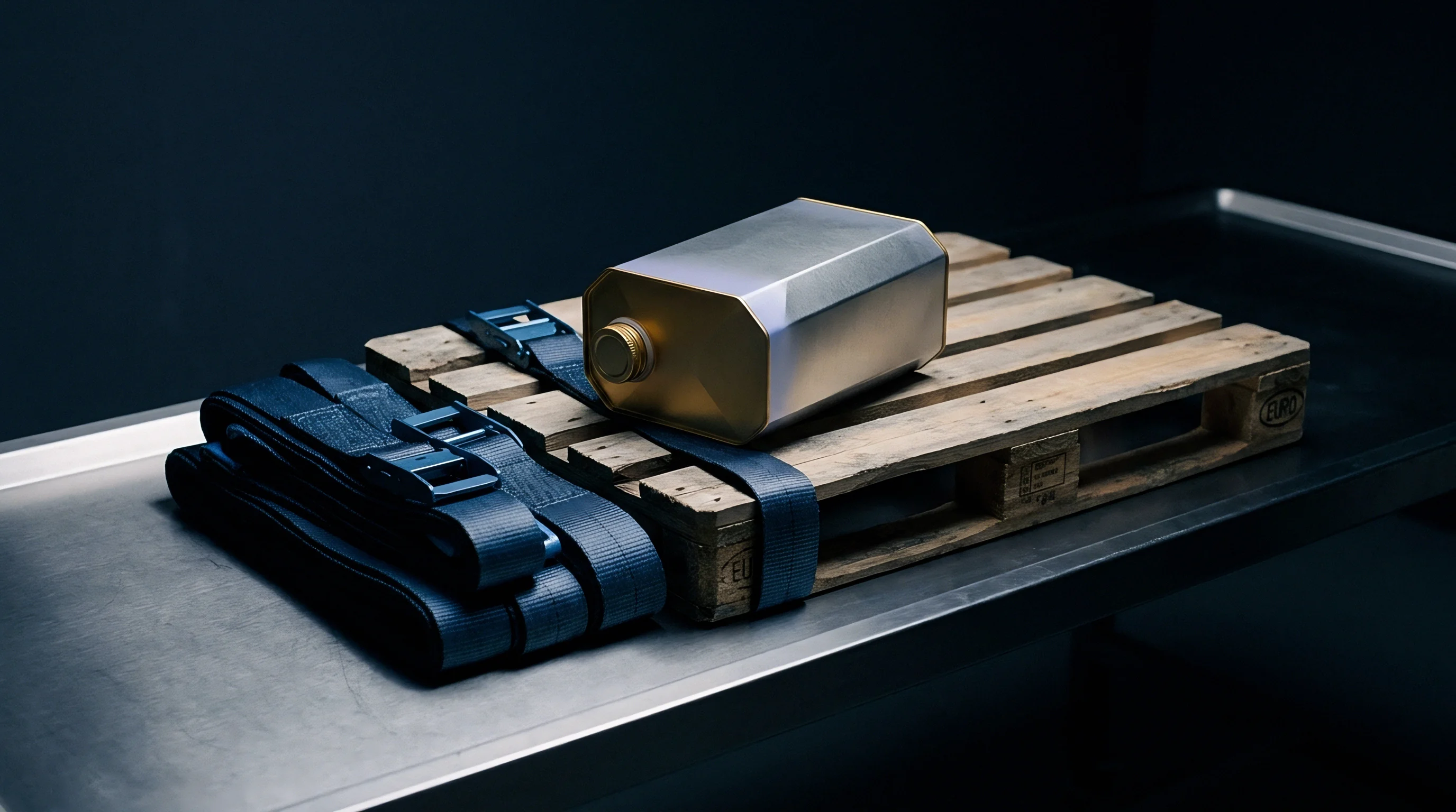
Ocean freight exposes containers to severe temperature swings and humidity cycles. Containers on deck absorb direct sunlight during the day, driving interior temperatures above sixty-five degrees Celsius. Rapid cooling at night causes moisture in the container air to condense on steel wall and ceiling panels.
This condensation, known as container rain, drips onto stacked pallets. Corrugated paperboard cartons absorb liquid water, losing structural strength until pallet stacks collapse. Collapsing cartons crush secondary packaging, breaking barrier seals and exposing cells directly to water.
Containerized Environmental Dynamics
Cargo holds undergo diurnal temperature cycles that drive rapid shifts in relative humidity. Air inside containers expands under peak solar heating and escapes through door gaskets. As temperatures drop at night, contracting air pulls humid sea air back inside.
This thermal breathing continuously pumps moisture into the container during ocean transit.
Equatorial routes present severe moisture challenges. Ships passing through the Suez or Panama canals encounter ambient humidity over ninety percent alongside sustained high temperatures. Over voyages lasting three to five weeks, moisture continuously diffuses through outer packaging if barrier specifications are inadequate.
| Packaging Level | Material Architecture | Primary Function | WVTR Rating (g/m²/24h) | Failure Mode |
|---|---|---|---|---|
| Primary Cell Seal | Laser Weld / Aluminum Laminate | Internal cell hermeticity | < 1.0 × 10⁻⁵ | Electrolyte hydrolysis |
| Secondary Bag | Aluminum Foil Barrier Sleeve | Cell cluster isolation | < 1.0 × 10⁻³ | Desiccant saturation |
| Inner Master Box | UN-certified corrugated fiberboard | Mechanical impact buffer | N/A (porous) | Structural collapse |
| Outer Container Barrier | Container liner / Calcium desiccant | Container rain prevention | N/A (absorptive) | Mold / pallet decay |
Container desiccants protect pallet shipments from internal condensation. Calcium chloride bags hung from lashing rings absorb up to three hundred percent of their dry weight in water vapor. Calcium chloride reacts with airborne moisture to form brine, which synthetic binding agents convert into a gel inside the pouch.
Determining desiccant requirements involves evaluating transit duration, cargo volume, and pallet moisture content. Wood pallets with over fifteen percent moisture release dozens of liters of water vapor when heated inside a container. Standard protocols require plastic pallets or kiln-dried wood pallets with less than twelve percent moisture to eliminate internal water sources.
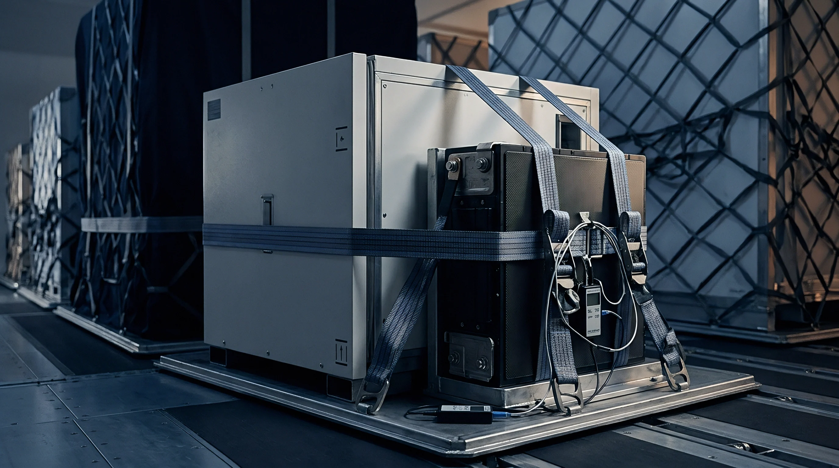
Landed Financial Damage Allocation
Moisture damage discovered during port entry inspections often leads to contractual disputes. Inspectors photograph container conditions, log indicator card readings, and pull samples for immediate moisture testing. Documenting damage before moving pallets off the port terminal establishes carrier liability.
Inadequate moisture protection adds hidden packaging waste and disposal overhead to landed costs.
Standard marine insurance excludes damage caused by inadequate packaging or inherent vice. If an insurer shows cell degradation stemmed from thin vacuum bags or missing desiccants, the buyer absorbs the loss. Specifying packaging standards directly in purchase contracts ensures financial recourse if shipments arrive damaged.
Containerized shipments passing through tropical ocean routes experience diurnal temperature swings of thirty degrees Celsius, driving moisture accumulation on unprotected master cartons.
Receiving inspections follow systematic sampling protocols. Engineers pull three master cartons from top, middle, and bottom pallet layers at the front and rear of the container. Samples are evaluated for open-circuit voltage, AC internal resistance at one kilohertz, and secondary bag vacuum.
Any bag showing loss of vacuum undergoes Karl Fischer moisture testing.
Landed-cost calculations routinely account for desiccant replacement at transshipment hubs.
Extreme container heat degrades door gaskets and secondary packaging seals over time.
Financial losses are measured by comparing scrap recovery against total landed inventory value. A forty-foot container carrying one hundred thousand cylindrical cells represents over five hundred thousand dollars in inventory. If moisture pushes internal water content past fifty parts per million, the entire shipment requires re-baking or scrapping, severely cutting into project margins.
In one typical shipping scenario, twenty thousand prismatic LiFePO4 cells were transported from East Asia to Europe. Container freight cost twelve thousand dollars, while total cell value reached eight hundred thousand dollars. Allocating an extra forty-five dollars per pallet for heavy-duty aluminum barrier bags and calcium chloride desiccants mitigated the risk of a total write-off.
Placing dual desiccant packs inside sealed master cartons prevents condensation on inner walls during transit through high-humidity equatorial routes.