Prismatic Cell Header Weld Thermal Strain under Solid Electrolyte Swelling
Solid-state prismatic cell swelling generates edge rotation bending strain at header weld roots, requiring wobble laser trajectories and compliant header contours to prevent premature fatigue failure.
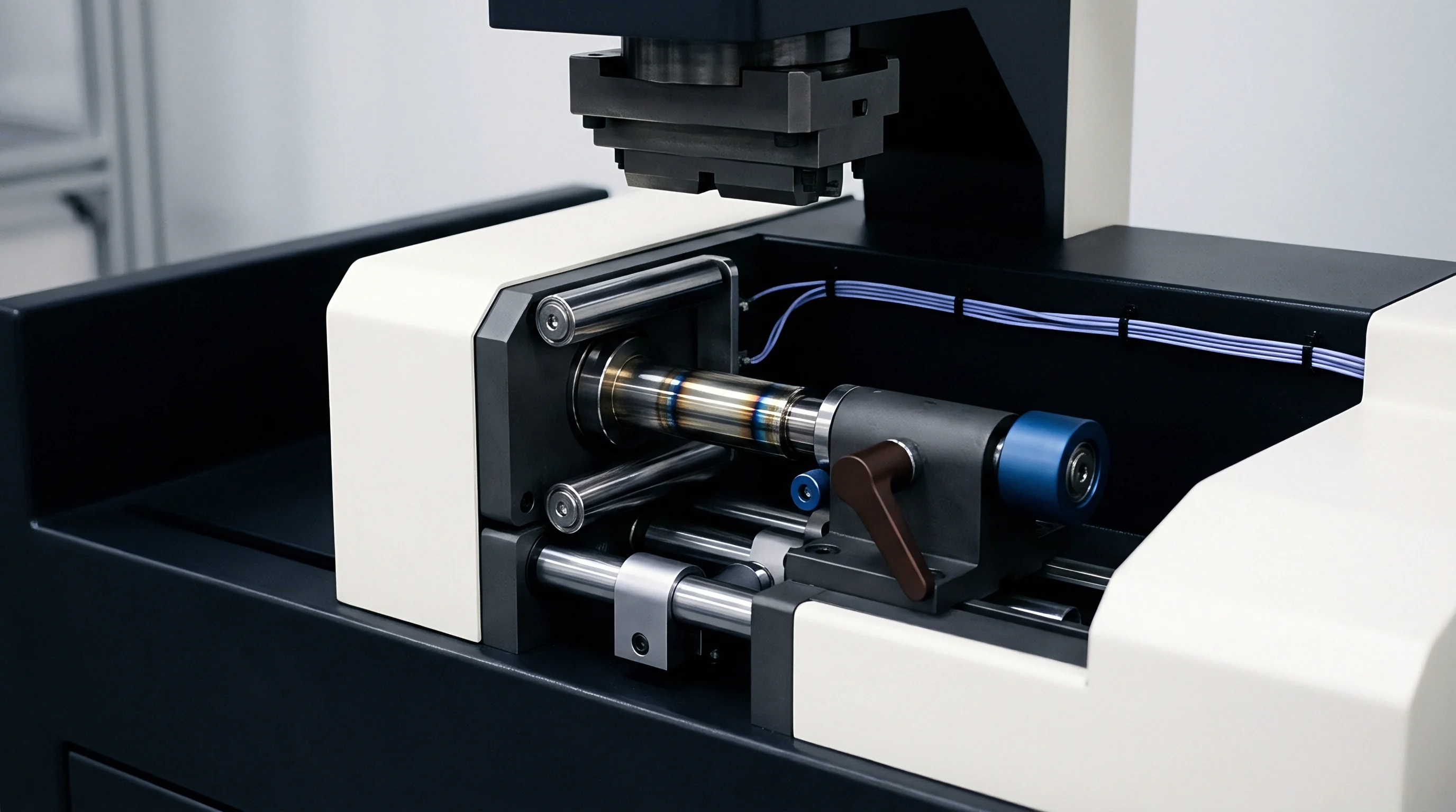

Deflection
Solid-state cells built with silicon-dominant or lithium-metal anodes experience substantial volumetric swings during operation. As lithium intercalates into silicon particles or plates directly onto the current collector, microscopic expansion accumulates into severe bulk displacement. In rigid prismatic packaging, this swelling exerts sustained outward thrust against the cell walls and top cover.
Maintaining intimate contact across solid-solid interfaces requires operating pressures between 2 MPa to 10 MPa depending on the active chemistry. Sulfide solid electrolytes in particular depend on continuous compression to suppress void growth and lithium dendrites, transferring steady mechanical loads into the housing.
This internal load bears directly against the top header plate. While drawn container walls can bow laterally against adjacent cells or thermal plates, the top cover is constrained along its perimeter by laser welds. Under internal pressure transmitted through the upper dielectric spacers, the cover deflects outward, generating high bending moments at the perimeter joint.
Header flexure sets up a steep through-thickness stress gradient across the seam, loading the interior weld root in tension while placing the exterior crown under compression.

Anisotropic Volume Expansion Mechanics
Preferential lattice expansion forces the cell stack upward into the header plate. Unlike porous polyolefin separators soaked in liquid electrolyte, rigid solid electrolyte layers offer no hydraulic compliance, passing swelling forces straight through the assembly. Plating pure lithium produces stack thickening that scales linearly with state of charge, adding roughly 5 micrometers of displacement per milliampere-hour per square centimeter of capacity.
Silicon composite anodes undergo particle swelling of up to 300 percent, which the rigid casing channels into uniaxial thrust against the cell ends. Header assemblies must tolerate these cyclic mechanical loads across thousands of cycles without yielding.
Centerline displacement of the top cover depends on plate thickness, alloy yield strength, and the aspect ratio of the can. Standard prismatic lids stamped from 3003-H14 or 1050 aluminum typically range from 1.0 mm to 2.0 mm thick to balance volumetric efficiency against bending stiffness. Under load, flexural strain peaks at the geometric center of the span and transfers reaction moments into the peripheral joint.
Once internal swelling exceeds structural design limits, high localized strain at the root of the weld initiates plastic deformation.
A rectangular 3003-H14 aluminum top cover measuring 148 mm by 26 mm with a 1.5 mm wall thickness exhibits 0.18 mm center-point axial displacement under 6 MPa uniform internal stack pressure.

Header Plate Flexure and Edge Bending Moments
From a structural standpoint, the top cover behaves as a thick rectangular plate clamped along its outer edge. Axial pressure against the inner face generates a severe moment profile, peaking along the long-edge perimeter weld. The bending moment per unit length at this boundary scales quadratically with the length-to-thickness ratio of the plate, leaving the narrow weld cross-section to resist edge rotation under load.
As the plate bows, rotation at the joint shifts the stress state from shear into opening-mode tension concentrated at the root notch. Thin wall sections adjacent to the weld toe absorb the bulk of this elastic-plastic strain. At peak state of charge, elevated internal pressure causes localized yielding in the aluminum.
Subsequent discharge reverses the deflection, driving cyclic strain reversals through the notch that gradually accumulate fatigue damage along the interior fusion boundary long before cracking surfaces on the outside of the cell.
External module endplates absorb a portion of operational displacement, though perimeter swelling still imposes severe cyclic strain on the internal joint.


Joint
Keyhole laser welding provides the primary hermetic enclosure seal between the deep-drawn prismatic can and the perimeter header. High-power continuous-wave fiber lasers operating at 1070 nm join the thin aluminum cover to the housing wall, typically using overlap or edge-butt joints between 0.8 mm and 1.2 mm thick. Travel speeds above 80 mm per second limit aggregate heat input, but the resulting rapid melt-pool quenching refines the centerline microstructure into fine equiaxed dendrites while coarsening grains within the heat-affected zone.
Joint reliability depends heavily on penetration depth, the internal root notch radius, and weld porosity. Solidification shrinkage and entrapped hydrogen voids create immediate stress risers under cyclic mechanical strain. When solid-state stack expansion flexes the lid, stress concentrates directly at the unwelded root interface.
This geometric discontinuity multiplies nominal bending stress by a factor of 2.5 to 4.2, depending on bead profile and root curvature.

Laser Fusion Metallurgical Characteristics
Volatilization of magnesium and manganese from 3000-series aluminum alloys inside the vapor keyhole alters the final composition of the fusion zone. Within the adjacent heat-affected zone, grain growth and precipitate coarsening degrade base-metal solid-solution strengthening. Tensile strength across this softened region drops by up to 30 percent relative to the cold-worked base alloy, lowering the local yield strength to roughly 85 MPa and reducing the threshold for cyclic plastic deformation during cell breathing.
Keyhole instability can also trap process gas in the weld root, forming spherical voids that reduce the effective load-bearing area where shear stresses peak.

Root Stress Distribution and Failure Initiation
Header flexure concentrates strain at the crevice where the cover seats against the inner can wall. Incomplete penetration leaves an unfused seam that acts as a sharp initial crack. Anode swelling applies opening-mode tension perpendicular to this seam, driving mode I crack growth.
High-speed optical monitoring during seam welding reveals how melt-pool fluctuations cause underbead sagging, sharpening the root notch and elevating local stress concentrations. Cyclic swelling then drives shear deformation across softened grain boundaries in the heat-affected zone, prompting microcracks to initiate at internal void clusters and propagate outward toward the surface.
| Joint Configuration | Laser Power (kW) | Weld Speed (m/min) | Penetration Depth (mm) | Max Root Shear Stress (MPa) |
|---|---|---|---|---|
| Standard Overlap Seam | 1.8 | 5.0 | 0.95 | 68.4 |
| Deep Penetration Butt | 2.2 | 6.2 | 1.20 | 42.1 |
| Flanged Edge Weld | 1.5 | 4.5 | 0.80 | 78.9 |
| Wobble Trajectory Overlap | 2.4 | 4.8 | 1.10 | 38.6 |
- Root Crevice Shear Fatigue occurs along the unmelted overlap seam line, where header flexure opens the internal notch under cyclic axial swelling.
- Heat-Affected Zone Softening Strain localizes plastic deformation in fully annealed aluminum next to the fusion boundary, lowering yield limits.
- Keyhole Porosity Crack Initiation starts at interior gas voids trapped during melt pool collapse, accelerating microcrack linkage along the central weld plane.
- Intermetallic Boundary Separation develops along coarse grain boundaries formed during the rapid solidification typical of high-power fiber laser welding.
An inadequate weld seam depth allows microcracks to travel through the root interface, destroying pack hermeticity and venting toxic electrolyte vapor into the enclosure long before reaching target cycle life.


Coupling
High discharge currents generate pronounced thermal gradients across the cell header assembly. Resistive heating develops at copper and aluminum terminal feedthroughs, while ohmic dissipation at internal busbar connections conducts heat directly into the top plate. Under heavy current pulses, temperatures peak around the terminals while the outer perimeter seam remains clamped near module cooling paths.
This differential expansion establishes steep localized stress fields across the cover.
Mismatches in thermal expansion coefficients between adjacent components compound this strain. Aluminum covers expand at roughly 23 multiplied by 10 to the minus sixth power per Kelvin, whereas ceramic or glass-to-metal terminal seals expand at substantially lower rates. This divergence imposes continuous shear stress across the feedthrough joints, which transfers into the adjacent header plate.
Superimposing thermal expansion over cyclic mechanical breathing produces a complex multi-axial strain state along the perimeter weld.
Thermal expansion mismatch at terminal feedthroughs amplifies microstructural strain along adjacent laser welds when high discharge C-rates coincide with peak solid-state stack pressure.

Transient Thermal Gradients across Aluminum Assemblies
High current pulses cause rapid thermal transients in the terminals. Sustained 3C discharge can drive a 25 K temperature rise across terminal posts in under 60 seconds. Heat conducts outward through the aluminum top cover toward the peripheral weld, which is kept cooler by ambient module airflow.
This temperature gap creates a temporary expansion differential between the center span and the constrained perimeter.
Compressive stress builds in the hot center of the cover plate, pushing material outward. Because the cooler welded perimeter restrains this growth, tensile stress spikes along the interior root of the girth seam as the aluminum softens.

Multi-Axial Thermal Mechanical Strain Tensor Analysis
Total strain at the weld root combines mechanical swelling, pressure-induced plate bending, and transient thermal expansion. The mechanical components track cell state-of-charge, while thermal strain follows current pulses. Phase shifts between peak swelling and peak thermal dissipation result in asymmetrical strain cycles.
At 8 MPa active stack pressure, peak deflection at the header center reaches 0.14 mm. During a continuous 3C discharge pulse at peak expansion, that 8 MPa swell pressure produces 0.12 percent mechanical bending strain at the interior root notch. Terminal ohmic heating concurrently drives the central header temperature 30 K above the perimeter frame, adding 0.07 percent constrained thermal expansion strain and pushing total effective strain at the notch to 0.19 percent.
At 55 degrees Celsius, the yield strain of annealed 3003 aluminum drops to 0.09 percent. Combined high-rate discharge and swelling push the weld root past its yield point into plastic deformation on every cycle. Dislocation pile-ups then accumulate at grain boundaries in the fusion zone, accelerating low-cycle fatigue.


Fatigue
Low-cycle structural degradation threatens the seal over thousands of breathing cycles. Anode expansion subjects the header weld to strain-controlled fatigue rather than stress-controlled loading, forcing fixed strain amplitudes onto the weld root with every charge. When these strain amplitudes exceed the elastic limit of the aluminum, Coffin-Manson relationships dictate fatigue life.
The plastic strain range per cycle governs how fast micro-damage accumulates. Higher stack pressures increase plastic strain, shortening the cycles needed to start macro-crack growth. Higher operating temperatures accelerate dislocation motion, grain boundary sliding, and creep-fatigue interaction, cutting endurance limits sharply.

Does Frame Compliance Prevent Weld Fatigue under Anode Swelling?
External module clamping designed to limit volume growth transfers strain directly back into internal components. Rigid endplates prevent overall stack expansion, causing swelling pressure inside the cell to climb exponentially. Internal pressures reaching 10 MPa drive high bending moments against the header plate.
Building controlled elastic compliance into the module reduces peak internal stack pressure and eases bending moments on the header weld. However, too much compliance increases total pack volume, hurting energy density and stressing busbar interconnects. Module compliance and header thickness have to be tuned together to balance weld fatigue against volume constraints.
| Test Condition ID | Stack Pressure (MPa) | Temperature Delta (°C) | Plastic Strain Range (%) | Cycles to Crack Initiation | Helium Leak Rate Post-Test (mbar·L/s) |
|---|---|---|---|---|---|
| Baseline Ambient | 3.0 | 10 | 0.02 | 4,800 | 1.2 × 10⁻⁹ |
| Moderate Pressure | 5.5 | 20 | 0.06 | 2,100 | 4.5 × 10⁻⁸ |
| High Thermal Strain | 5.5 | 45 | 0.11 | 1,050 | 8.8 × 10⁻⁶ |
| Severe Combined Load | 8.5 | 45 | 0.18 | 380 | 2.1 × 10⁻3 |
- Mount the sample cell assembly into a uniaxial hydraulic fatigue test rig fitted with a thermal environmental chamber.
- Install a laser displacement sensor array over the central span of the top cover and high-frequency strain gauges at the girth weld toes.
- Apply sinusoidal pressure cycles between 2 MPa and 8 MPa at 0.1 Hz while cycling an internal heating element to simulate 30 K thermal transients.
- Monitor acoustic emission channels continuously to detect early microcracking in the weld root.
- Perform helium mass spectrometer leak detection every 250 cycles to verify hermetic seal integrity below 10 to the minus eight mbar liters per second.
Standard IEC 62660-2 thermal-mechanical stress profiles fail to capture solid-state stack expansion forces, requiring customized acceptance clauses to prevent premature field weld ruptures.
Under section 8.3 of master cell purchase agreements, custom clauses specify that any seal degradation exceeding 10 to the minus six mbar liters per second before 1,500 full depth-of-discharge cycles constitutes a structural material defect ~ transferring all warranty liability and replacement costs directly to the cell manufacturer.


Margin
Header geometry dictates whether local strains stay safely within the material’s elastic limit. Standard flat covers are the most vulnerable profile because bending spreads uniformly across a thin cross-section. Modified designs use varied stiffness, relief contours, and advanced laser motion profiles to protect fatigue margins under solid electrolyte pressure.
Integrating mechanical relief grooves or bellows directly into the stamped aluminum header creates internal compliance. These formed contours absorb axial displacement by bending away from the perimeter weld. Relieving edge rotation lowers tensile stress at the root notch below critical limits.
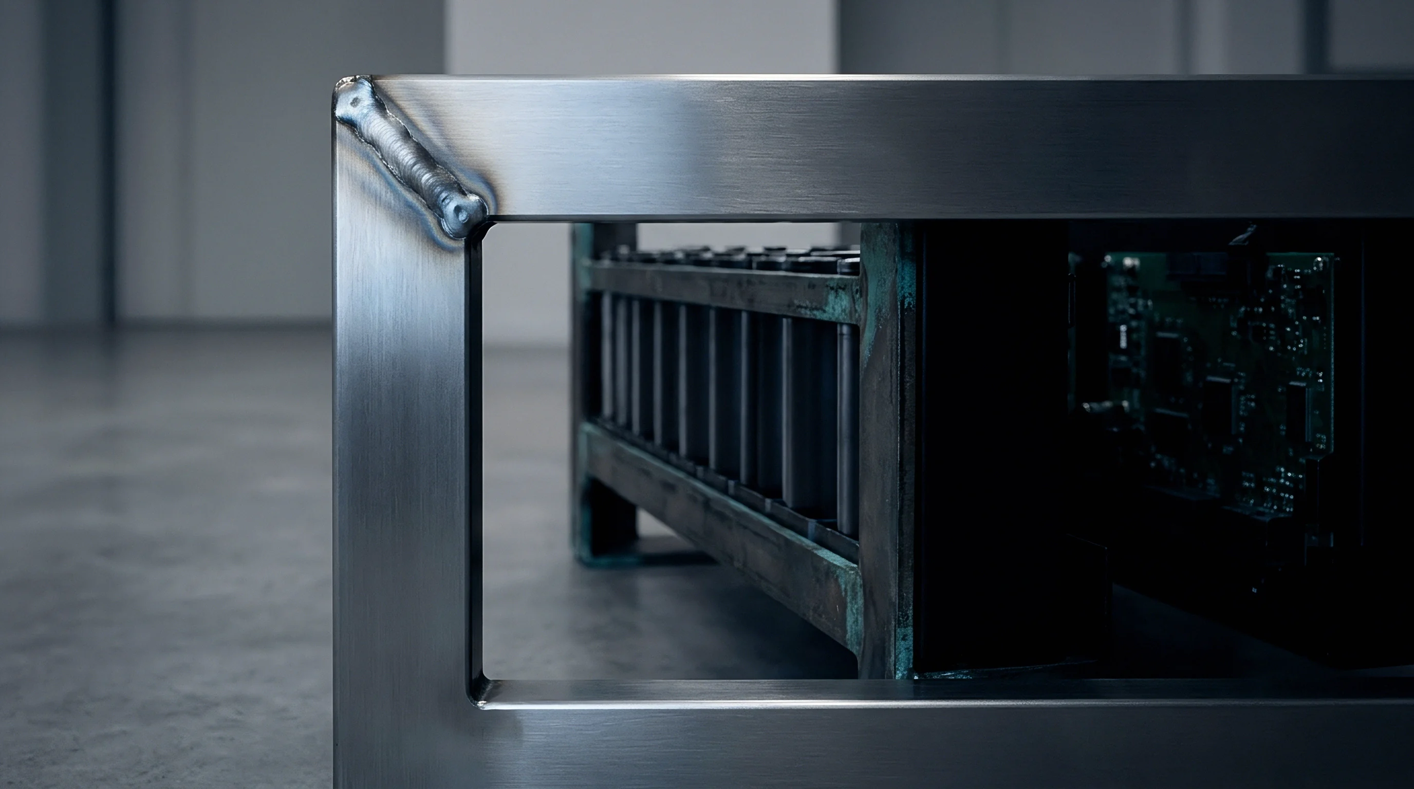
Geometrical Strain Relief and Header Contouring
Stamping concentric recessed grooves into the header plate near the weld zone creates flexible hinges. As axial thrust pushes the center section upward, the hinge deflects elastically to prevent edge rotation at the joint. FEA modeling shows that a 0.5 mm deep recessed contour drops peak root notch stress from 110 MPa down to 48 MPa under an 8 MPa internal swelling load.
Profiling plate thickness optimizes structural mass, channeling bending energy into compliant regions via a rigid 2.0 mm central span that tapers to a 1.0 mm perimeter flange to protect margins at the laser seam, though tooling complexity increases accordingly.

Laser Wobble Parameter Optimization
Oscillating the laser beam trajectory during seam welding improves joint strain resistance. High-speed galvo-scanning heads move the spot in circular, transverse, or figure-eight patterns at up to 300 Hz along the seam. This wobble widens the weld cross-section and increases effective throat thickness without adding excessive heat that coarsens nearby grains.
Programming the optical scanning head with asymmetric wobble amplitudes on 3003 aluminum lid welds smooths the internal root radius transition, cutting the geometric stress concentration factor Kt from 3.8 to 1.9. Cast dendrites in the fusion zone also adopt a randomized orientation, improving resistance to microcrack growth along grain boundaries.
| Header Geometry Design | Nominal Wall Thickness (mm) | Relief Contour Depth (mm) | Stress Concentration Factor (Kt) | Peak Root Stress at 8 MPa Load (MPa) |
|---|---|---|---|---|
| Flat Standard Stamping | 1.2 | None | 3.85 | 118.2 |
| Thickened Uniform Plate | 2.0 | None | 3.10 | 72.4 |
| Single Bellows Contour | 1.2 | 0.4 | 2.15 | 51.6 |
| Dual Groove Diaphragm | 1.5 Center / 1.0 Edge | 0.6 | 1.75 | 36.8 |
- Header Profile Compliance Tuning balances central bending stiffness against peripheral edge rotation to minimize weld root stress.
- Wobble Frequency Beam Trajectory Selection controls solidification dynamics in the weld pool, widening the weld throat and smoothing internal root radii.
- Localized Thickness Stamping Distribution concentrates rigidity along the central span while forming compliant elastic hinges near perimeter welds.
- Internal Foam Cushion Integration adds elastic compressive resistance directly above the stack to damp pressure spikes before they reach the header.
Oscillating laser wobble trajectories widen the weld seam root width, distributing bending strain across a broader fusion zone cross-section.
Whether high-strength aluminum alloys can withstand long-term stress corrosion cracking under continuous sulfide electrolyte exposure remains an open question for long-life storage systems.

Clause
Commercial cell specifications need to explicitly define total allowable volumetric expansion alongside helium leak rate thresholds. Standard procurement documents historically focused only on initial capacity, internal resistance, and weight. Sourcing solid-state cells demands strict mechanical limits covering maximum lid deflection, end-of-life breathing displacement, and dynamic stack pressure.
Without these boundaries in supply contracts, pack integrators take on enclosure rupture liabilities when cells expand beyond module cavity tolerances.
Sourcing engineering relies on clear warranty boundaries tied to mechanical strain metrics. RFQs should detail exact test fixtures, clamping parameters, and thermal cycling environments used to validate fatigue life. Failure responsibility then splits cleanly: either cell swelling pressure exceeded agreed specification limits, or weld seam quality failed initial micro-CT inspection.

Procurement Specification Parameters for Solid-State Cells
Technical requirement schedules attached to supply agreements must state maximum expansion tolerances under specific stack compression profiles. Center-point deflection on the top header cover cannot exceed 0.10 mm across declared cycle life at a nominal operating stack pressure of 5 MPa.
Explicit stack expansion boundaries in master agreements prevent downstream disputes by establishing precise pressure windows, requiring suppliers to guarantee seal integrity up to 12 MPa peak internal pressure to accommodate thermal runaway or gas evolution during deep overdischarge.

Quality Acceptance Thresholds and Inspection Verification
First-article inspection routines for solid-state prismatic cells require non-destructive volumetric analysis of every perimeter laser seam. Industrial X-ray micro-CT scans inspect fusion depth and flag internal keyhole voids larger than 30 micrometers. Weld seam porosity over 1.5 percent of total bead volume is cause for immediate lot rejection.
Helium mass spectrometry leak testing serves as the ultimate benchmark for seal integrity. Production line testing requires fine leak verification below 1.0 times 10 to the minus eight mbar liters per second after mechanical pre-conditioning. Pressure hold testing verifies burst margins up to 2.5 MPa gauge pressure, ensuring adequate safety margins during transit, storage, and operation.
Always bound cell swelling limits at the single-cell drawing boundary before finalizing module structural stiffness parameters.