Quantifying Scalable In-Situ Sacrificial Additive Kinetics for Mass Produced Sodium Cell Formation Lines
Sacrificial cathode additive kinetics dictate sodium cell formation time, gas volume, and interphase impedance, governing plant CapEx and landed cost per kWh.
Precursor
Sacrificial Stoichiometry and Initial Sodium Trapping
Hard carbon negative electrodes consume a substantial fraction of active sodium during initial charge. This irreversible loss stems from electrolyte solvent reduction on the disordered carbon surface ~ which forms a passivating film ~ and structural sodium trapping within defects and inter-graphene layers. In sodium-ion cells with layered oxide cathodes like NaNi0.33Fe0.33Mn0.33O2 or polyanionic frameworks like Na3V2(PO4)3, the cathode provides all active sodium.
If twenty percent of those ions become permanently trapped at the anode during first charge, usable discharge capacity drops by twenty percent. Blending sacrificial pre-sodium additives into the positive electrode supplies extra sodium cations without taking up reversible intercalation sites in the main host lattice.
Sodium oxalate (Na2C4O4) acts as a high-capacity sacrificial agent that releases two sodium ions per molecule during anodic oxidation. Its theoretical specific capacity reaches 400 mAh/g based on a molecular weight of 133.99 g/mol. Between 3.75 V and 4.10 V vs Na/Na+, the oxalate anion undergoes irreversible electrochemical oxidation, breaking down into gaseous carbon dioxide and releasing sodium cations into the electrolyte.
These cations migrate across the separator to build the solid electrolyte interphase and fill defect sites in the hard carbon.
| Additive Molecule | Decomposition Potential Range (V vs Na/Na+) | Theoretical Specific Capacity (mAh/g) | Gaseous Byproduct Species | Theoretical Gas Generation (mL/g at STP) | Solid Residue Mass Fraction (%) |
|---|---|---|---|---|---|
| Na2C4O4 (Sodium Oxalate) | 3.75 – 4.10 | 400 | CO2 | 334.4 | 0.0 |
| Na2C2O4 (Sodium Oxalate Dimer) | 3.85 – 4.20 | 400 | CO2 | 334.4 | 0.0 |
| Na2O (Sodium Oxide) | 3.55 – 3.90 | 865 | O2 | 180.7 | 0.0 |
| NaN3 (Sodium Azide) | 3.60 – 3.85 | 412 | N2 | 516.9 | 0.0 |
| Na2S (Sodium Sulfide) | 3.40 – 3.75 | 687 | S (Elemental) | 0.0 | 41.1 |
Other inorganic additives show clear electrochemical trade-offs during formation. Sodium azide yields high specific capacity alongside nitrogen gas evolution, but toxicity during slurry preparation limits its industrial use. Sodium oxide offers theoretical capacity exceeding 800 mAh/g, yet its strong basicity causes polyvinylidene fluoride binder solutions to gel prematurely in N-methyl-2-pyrrolidone.
Sodium sulfide leaves elemental sulfur in the cathode pores, disrupting electronic conductivity during extended cycling. As a result, dicarboxylic sodium salts remain the practical choice for high-volume automated lines.
Slurry homogeneity determines how uniformly the additive decomposes across the composite cathode coating. Sacrificial particles require uniform dispersion alongside conductive carbon networks to avoid localized overpotentials. If particle sizes exceed five micrometers, oxidation remains incomplete at standard charge rates, leaving unreacted insulating pockets that impair electronic percolation.
Micro-milling sodium oxalate to a median particle size below two micrometers allows complete extraction within normal formation schedules and prevents clogging in slot-die coating heads.
Baseline capacity retention drops by 4.2 percent when formation currents exceed 0.2C during initial additive extraction. High current densities drive strong localized concentration polarization, pushing local electrode potential above 4.3 V vs Na/Na+ before the sacrificial compound reacts completely. Crossing this upper voltage limit accelerates solvent breakdown, oxidizing ethylene carbonate and ethyl methyl carbonate into organic acids that attack aluminum current collector foils.
Careful potential control during first charge isolates additive extraction from solvent decomposition.

Electrochemical Reaction Mechanisms and Gas Generation
The irreversible oxidation of sodium oxalate follows a multi-step electron transfer. A single-electron oxidation first generates a radical oxalate intermediate bound to the cathode surface, followed by rapid decarboxylation that releases two molecules of carbon dioxide gas and ejects the remaining sodium ion into solution. Because these gaseous products escape the solid electrode matrix, no inactive residue remains in the cathode pores to impede sodium-ion diffusion after formation.
Sodium oxalate decomposition yields 334.4 milliliters of carbon dioxide gas per gram of additive under standard temperature and pressure conditions.
Quantifying gas evolution kinetics requires tracking the differential capacity curve during formation charge. A distinct oxidation peak appears between 3.80 V and 3.95 V vs Na/Na+, clear of the main intercalation plateau. Integrating current over this window gives the total charge delivered to the sacrificial additive; comparing that charge with mass spectrometer gas data determines the faradaic efficiency of the decomposition on production lines.
Electrolyte composition directly influences the decomposition potential and oxidation kinetics of sacrificial additives. Sodium hexafluorophosphate in alkyl carbonate mixtures shows low background current up to 4.2 V vs Na/Na+, offering a suitable window for oxalate extraction. Adding fluoroethylene carbonate to build the SEI lowers the onset potential of anode film formation to 0.6 V vs Na/Na+, so the anode passivates before the cathode additive releases the bulk of its sodium.
This order of reactions stops unpassivated hard carbon from catalyzing secondary reactions with evolved gases.
Evaporation of low-boiling electrolyte components can skew online gas pressure measurements during formation. Pressure monitoring systems on formation channels need to distinguish true electrochemical gas evolution from thermal solvent vaporization. Clamped thermal management plates must hold cell temperatures within a narrow band to stabilize liquid-vapor equilibria when current steps change.
Mechanical stress builds in the positive electrode as sacrificial additive particles dissolve and react. As solid mass disappears, microscopic voids form, changing the internal porosity and tortuosity of the cathode. Calendering routines must account for this shrinkage to preserve structural integrity and low contact resistance between active grains and carbon black.
Weak binder crosslinking leads to cathode delamination under internal gas pressures during fast formation.
Whether trace organic fragments from incomplete oxalate oxidation remain adsorbed on cathode surfaces ~ and alter high-voltage transition metal dissolution during extended operation ~ remains unclear.

Gas
Venting Infrastructure and Pouch Pocket Volumetrics
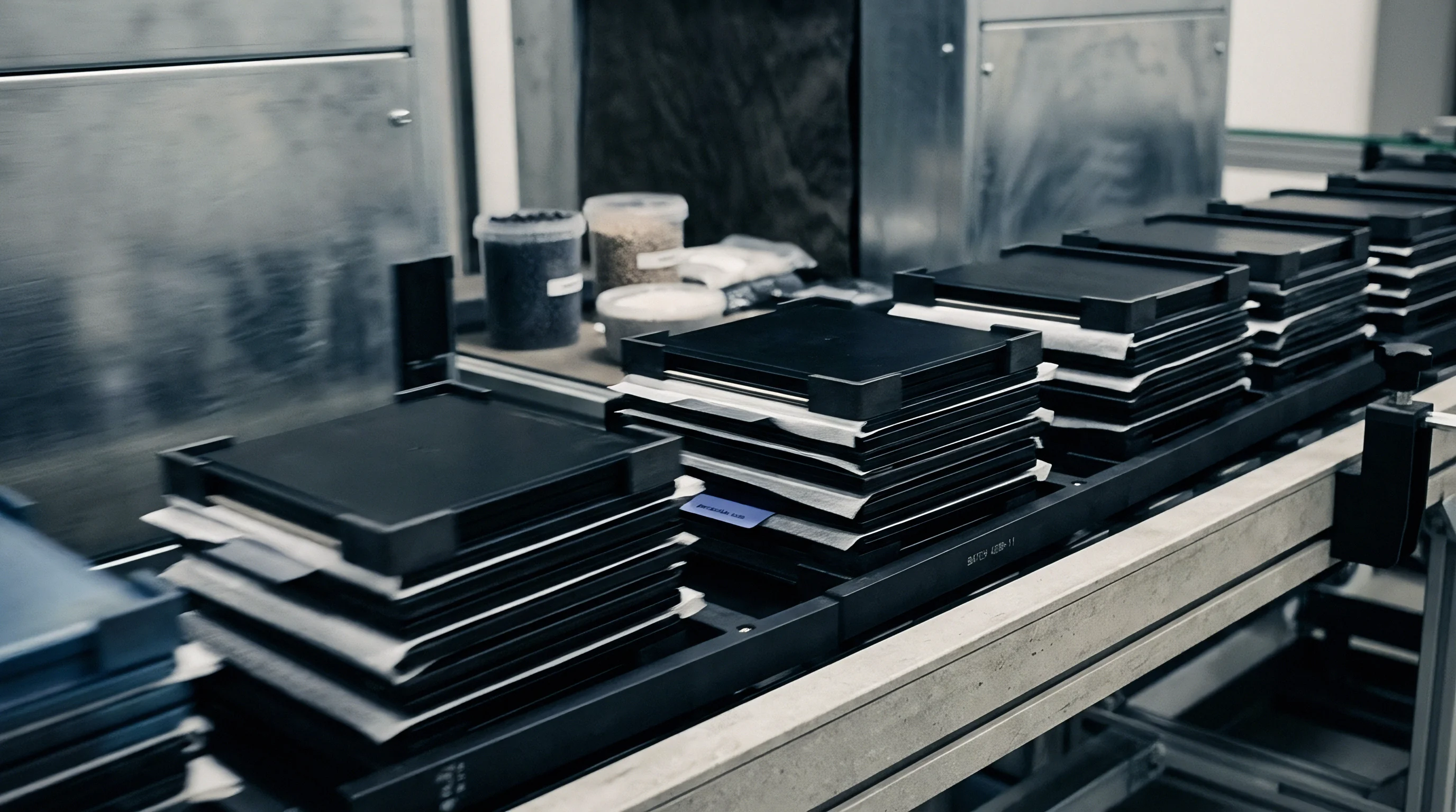
Gas generation during volume cell formation requires dedicated containment and extraction hardware. Pouch-format sodium-ion cells feature temporary chambers ~ pouch pockets ~ welded directly to the active cell compartment. These foil extensions collect carbon dioxide, nitrogen, or vaporized solvents during initial charge without over-pressurizing the main cell package.
Sizing these pockets involves balancing physical footprint on formation trays against allowable pressure rise.
Calculating pocket volume depends on how much sacrificial additive is loaded into the cathode coating. A 20 Ah sodium-ion pouch cell with three weight percent sodium oxalate in a 15 g cathode coating contains 0.45 g of additive. Complete oxidation generates roughly 150 mL of carbon dioxide at ambient pressure and 45 °C formation temperature.
The temporary pocket must exceed this expected volume by at least twenty percent to protect the main heat seals from stress.
Prismatic sodium-ion cells in rigid aluminum cans rely on temporary mechanical vent valves during formation. Automated racks attach gas lines to these ports to keep negative pressure in the cell headspace. Exhaust lines route evolved gases to scrubbers that neutralize acid vapors and collect solvent droplets.
Laser-welding the final fill port happens only after formation is complete and deep vacuum degassing is done.
Tracking voltage plateau shifts in formation logs confirms complete additive oxidation. Incomplete extraction leaves gas bubbles trapped between separator sheets and electrode surfaces. These trapped bubbles block sodium-ion flow and create localized high-current spots during cycling, which can trigger sodium plating on the hard carbon anode, dendrite growth, and internal micro-shorts.
Pressure plates clamp pouch cell faces with steady mechanical force during charging. Uniform pneumatic pressure between 0.2 MPa and 0.6 MPa forces gas bubbles out of the porous electrode into the secondary pocket. Uneven clamping causes thickness variation across the cell, shifting internal resistance across production lots.
Degassing Protocols and Mass Transfer Rates
Removing evolved gases from formed sodium cells requires controlled vacuum evacuation before final sealing. Automated lines move clamped pouch cells to degassing stations running at absolute pressures between 5 kPa and 15 kPa. The draw-down must extract gas from the electrolyte without boiling volatile solvents like dimethyl carbonate or ethyl methyl carbonate.
- Mechanical Decapitation Piercing tools puncture the temporary gas pocket within an evacuated seal chamber to vent accumulated carbon dioxide and nitrogen.
- Primary Vacuum Pull Chamber pressure drops to 20 kPa at a controlled rate of 5 kPa per second, drawing bulk gas volumes out of the pocket headspace.
- Electrolyte Degassing Step Pressure cycles between 10 kPa and 30 kPa three times to extract dissolved gas species from the liquid electrolyte phase without causing solvent boiling.
- High-Vacuum Stabilization Final pressure holds at 5 kPa for ten seconds while sensors measure chamber vacuum decay rates to verify zero liquid electrolyte carryover.
- Final Thermal Impulse Seal Heated sealing jaws clamp below the puncture point at 180 °C under 0.4 MPa pressure, creating a permanent hermetic perimeter seal.
- Secondary Pocket Trimming Guillotine blades sever the temporary gas pocket, routing trimmed aluminum laminate scrap to dedicated recycling collection chutes.
Vapor pressure limits set the maximum safe vacuum depth during degassing. Pulling chamber pressure below the electrolyte’s bubble point triggers fast solvent evaporation, altering solution stoichiometry and raising viscosity. Thicker electrolyte slows sodium-ion transport, reducing rate capability and cold-weather performance in the finished cell.
Temperature control inside degassing chambers prevents solvent evaporation while maintaining low gas solubility in the carbonate mixture. Carbon dioxide dissolves less in alkyl carbonates at higher temperatures, speeding up degassing at 40 °C compared to 20 °C room temperature. However, higher temperatures speed up side reactions between trace moisture and sodium salts, forming hydrofluoric acid that attacks cathode active particles.
Monitoring total gas volume collected during vacuum degassing offers a clear check on additive reaction yield. Yields below ninety percent of theoretical values point to incomplete additive oxidation, signaling possible channel faults or improper temperature profiles across formation trays.
Applying steady press force during vacuum sealing squeezes remaining micro-bubbles out of the separator into the pocket before trimming.

Rates
Kinetically Limited Oxidation and Temperature Dependencies
Decomposition kinetics of the sacrificial additive govern how long cells must stay on formation channels. Unlike intercalation reactions with fast charge transfer, breaking chemical bonds in organic additives requires higher activation energy. Sodium oxalate oxidation requires breaking carbon-carbon bonds in the oxalate anion, creating a kinetic barrier that shows up as a noticeable overpotential at room temperature.
Arrhenius modeling shows that decomposition rates depend strongly on formation temperature. Running channels at 25 °C requires C-rates around 0.02C to avoid over-potentializing the cathode. Raising tray temperatures to 45 °C accelerates reaction kinetics by a factor of 3.4, letting formation currents reach 0.08C without crossing upper voltage limits.
This cuts total formation time from 48 hours to under 18 hours per batch.
| Formation Temp (°C) | Maximum Safe C-Rate | Oxidation Overpotential (mV) | Additive Extraction Time (h) | Gas Generation Rate (mL/min/Ah) | SEI Resistance R_sei (mΩ) | |
|---|---|---|---|---|---|---|
| 25 | 0.02C | 280 | 35.0 | 0.08 | 14.2 | |
| 35 | 0.04C | 190 | 17.5 | 0.17 | 11.5 | |
| 45 | 0.08C | 110 | 8.8 | 0.36 | 8.7 | |
| 55 | 0.12C | 65 | 5.8 | 0.58 | 12.8 |
Overpotentials during additive extraction shift the potential across both electrodes. High overpotentials push the cathode into regions where solvent oxidizes alongside the additive. Co-oxidizing electrolyte solvents generates free radicals that polymerize into resistive, high-impedance films on cathode surfaces.
Keeping overpotentials under 120 mV ensures selective oxidation of the sacrificial compound without triggering solvent breakdown.
Evaluating incoming cathode slurry formulations requires verifying additive particle size distributions. Finer additive particles provide higher surface area per unit volume, lowering local current density and kinetic activation overpotentials. A log-normal distribution with a d90 under 1.8 micrometers ensures quick dissolution in the electrolyte during the initial wetting phase before current is applied.
Mass transport of dissolved additive species through electrode pores limits extraction currents. In thick coatings designed for high areal capacity cells exceeding 3.0 mAh/cm², diffusion of oxalate anions from particle interiors to carbon black reaction sites limits reaction speed. Protocols must use stepped current profiles ~ starting low to clear surface additive before stepping up once concentration gradients build within the pores.
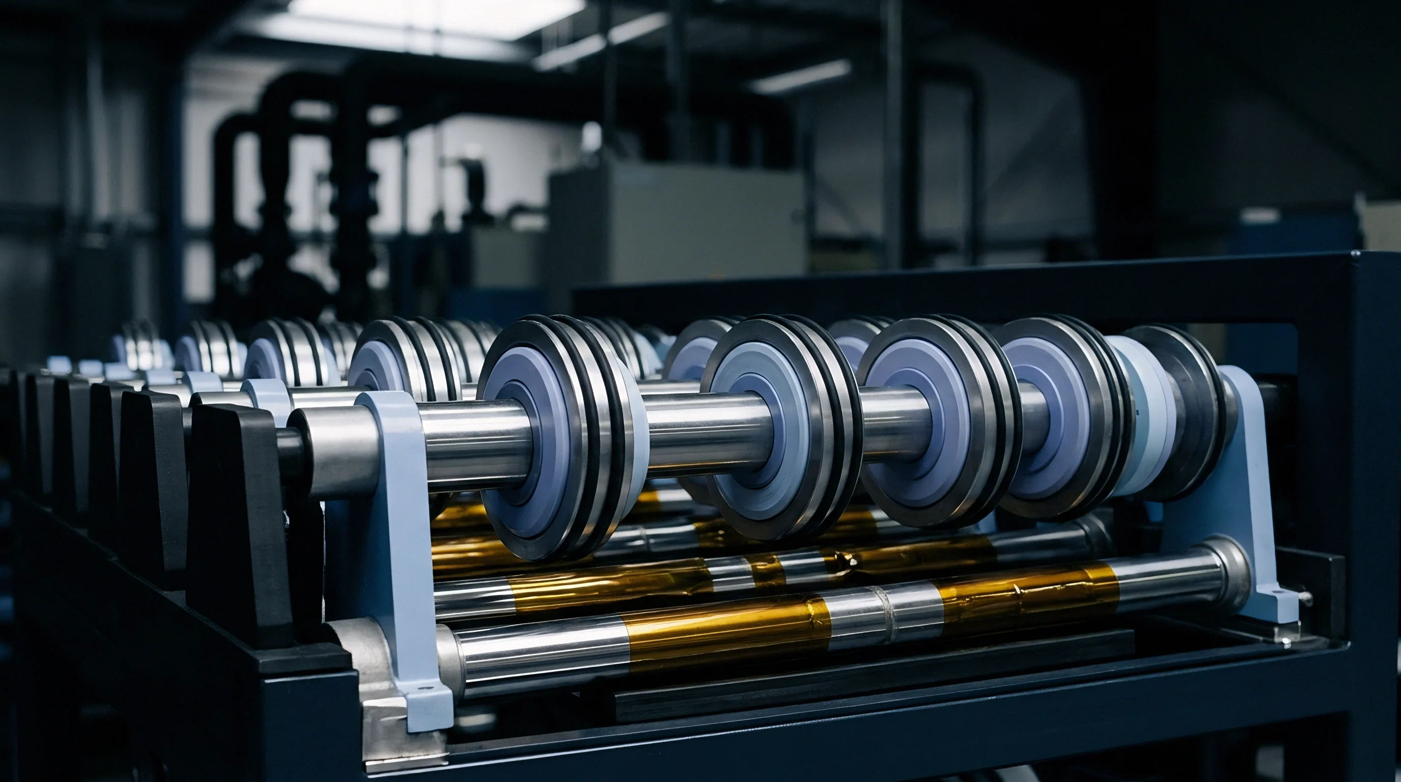
Does Elevated Decomposition Temperature Degrade Hard Carbon Interlayers?
Raising formation temperatures above 50 °C to speed up additive reaction kinetics introduces real degradation risks at the hard carbon anode. While heat improves bulk electrolyte conductivity, it changes how the solid electrolyte interphase precipitates. Hard carbon exposed to high temperatures during initial sodium reduction forms thicker, less compact films dominated by inorganic sodium carbonate and sodium oxide.
Sodium carbonate deposits formed at high temperatures lack mechanical elasticity under cyclic volume changes. As hard carbon expands and contracts during cycling, fragile inorganic films crack and expose fresh carbon to the electrolyte. This drives ongoing electrolyte consumption, accelerating capacity loss and raising cell impedance over time.
Formation temperatures above 50 °C increase initial interphase growth rates while accelerating long-term capacity degradation due to inorganic film cracking.
Thermal acceleration of additive kinetics should therefore stay within a strict window of 40 °C to 48 °C. Operating in this thermal range maintains fast additive extraction while preserving organic-rich sodium alkyl carbonate interphases on the hard carbon. Uniform temperatures across multi-cell press plates prevent channel-to-channel variation in interphase thickness and composition.
Porous separator membranes also react to heat during high-temperature formation. Polyolefin separators held under pressure at elevated temperatures can suffer localized pore shrinkage, restricting sodium-ion transport. Ceramic-coated polyolefin or non-woven aramid separators maintain structure and porosity under heat, allowing fast additive kinetics without raising ionic resistance.
Poor step timing during current-controlled formation allows the cathode potential to drift into solvent decomposition voltages, causing permanent capacity loss and excessive gas expansion before degassing.

Chamber

Line Engineering and Press Tray Integration
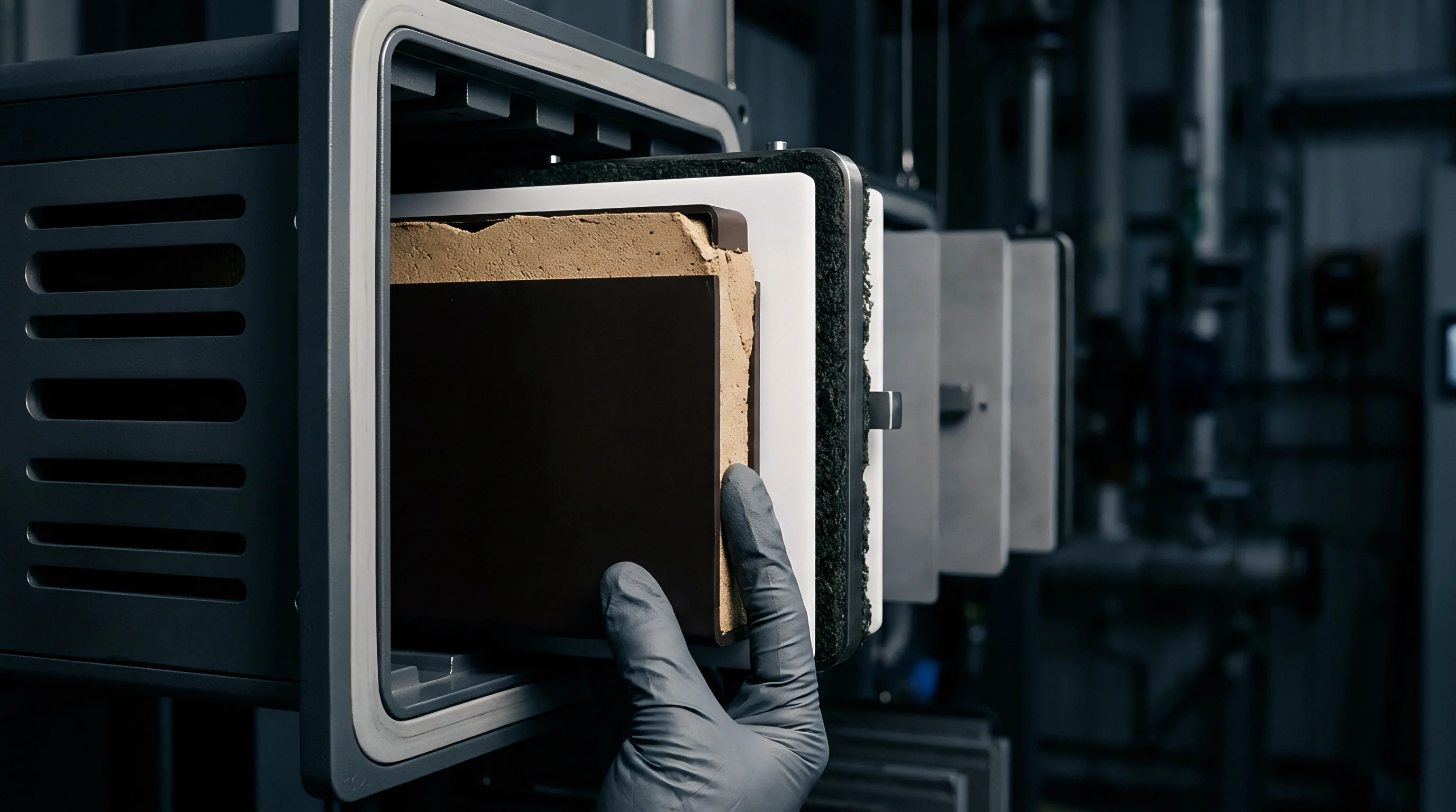
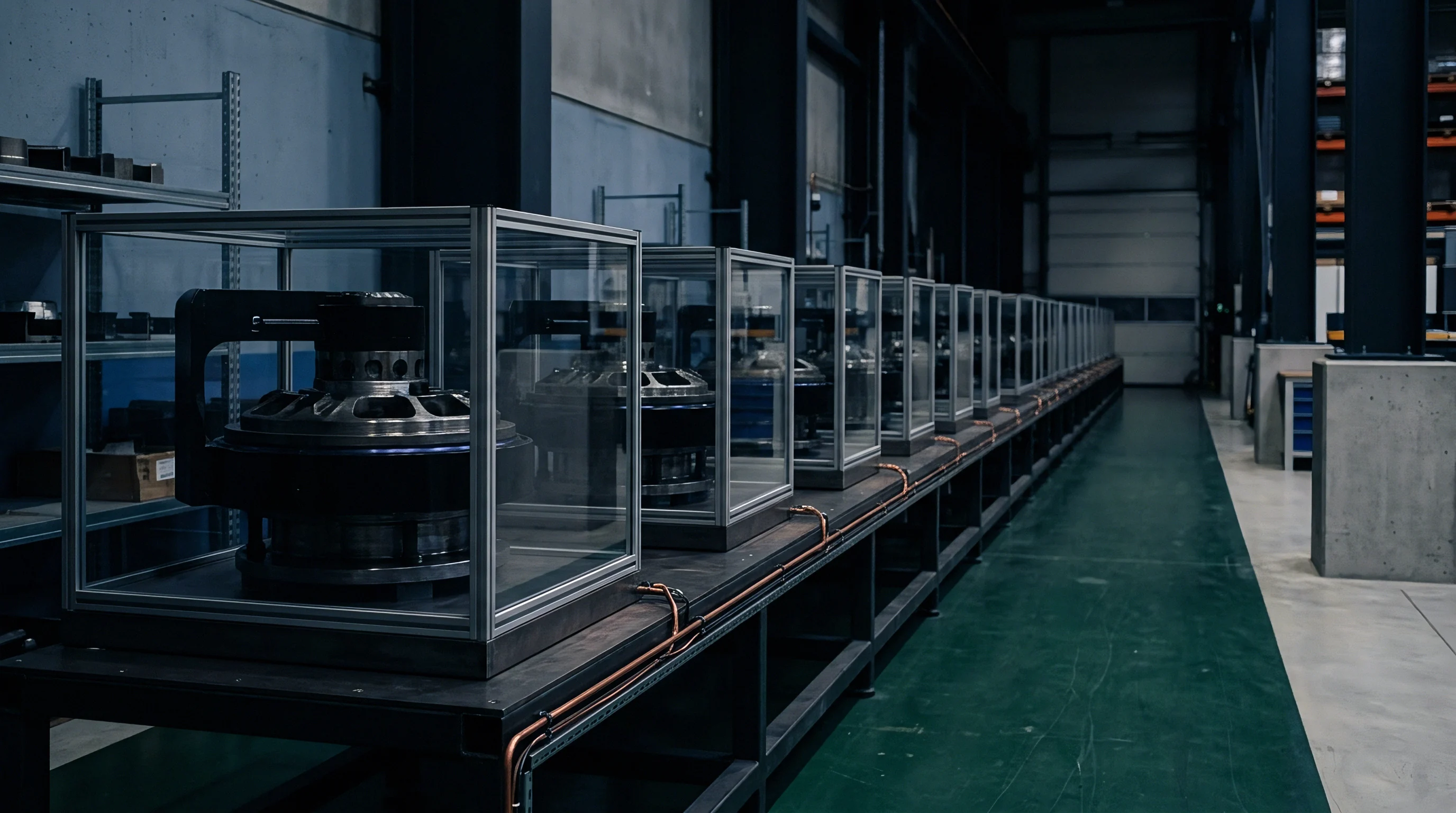
Volume cell formation lines require integrated hardware capable of handling electrical charge-discharge channels, mechanical clamping, thermal management, and gas exhaust at the same time. Modern factories deploy automated cabinets housing multi-tier trays. Each tray holds up to 64 pouch or prismatic cells, connecting cell terminals through high-current spring pins linked to individual bi-directional inverter channels.
Mechanical presses integrated into formation trays apply controlled clamping force across cell faces during the initial charge cycle. Pneumatic actuators or servo-driven plates maintain forces between 1.5 kN and 5.0 kN per cell, ensuring low contact resistance at current collector tabs while pushing evolved carbon dioxide out of electrode voids into temporary pouch pockets. Load cells built into the press plates feed force data to line controllers, compensating for thermal expansion as cells heat during charging.
Thermal control systems in the press plates regulate cell temperatures across multi-channel trays. Internal channels circulating silicone fluid or water-glycol mix keep plate surface temperatures within ±0.5 °C of setpoint. Fast thermal response allows dynamic temperature stepping ~ raising heat during additive decomposition and cooling cells before vacuum degassing.
Automated tray loading systems use robotic gantries to transfer cells from electrolyte filling and wetting racks into formation cabinets. Blind-mate electrical and quick-disconnect pneumatic fittings engage automatically when trays slide into cabinet slots, cutting manual handling and worker exposure to high DC voltages. Built-in fire suppression floods individual slots with argon or nitrogen if thermal runaway or solvent leaks occur.
Formation yield thresholds tie directly to electrolyte moisture specifications in supply agreements. Water contamination above twenty parts per million reacts prematurely with sacrificial additives, forming insoluble sodium hydroxide deposits that clog cathode pores and lower line yields.

Yield Bottlenecks and Line Throughput Balancing
Adding sacrificial additive decomposition steps changes the throughput calculation for a formation line. Standard lithium-ion formation relies on a simple low-current charge to build the SEI, usually taking 12 to 24 hours. Sodium-ion cells with sacrificial additives require multi-step protocols with distinct voltage holds for additive extraction, gas accumulation, and elevated-temperature interphase curing.
- Low-Current Initial Seeding Segment Charge at 0.02C up to 2.5 V vs Na/Na+ establishes initial anode passivating layers while preventing rapid gas evolution.
- Additive Extraction Voltage Hold Stepped potential hold at 3.90 V for six hours allows complete oxidation of sacrificial sodium oxalate without over-potentializing solvents.
- High-Current Bulk Intercalation Charge Charge step at 0.1C carries cell voltage from 3.9 V to upper cutoff limit of 4.1 V, completing bulk sodium loading.
- Thermal Stabilization Phase Temperature ramps down from 45 °C to 22 °C under continuous 0.3 MPa press force, preparing cell packages for vacuum extraction.
- Degassing and Vacuum Sealing Transit Automated conveyor transfer to vacuum sealing chambers extracts accumulated gas pockets within a ninety-second cycle window.
Capital expenditure scales directly with formation cycle length. A factory producing 5 GWh of sodium-ion cells annually requires over 30,000 active channels if formation takes 36 hours. Cutting formation time to 18 hours through kinetic optimization and thermal acceleration halves cabinet footprint and saves millions in upfront equipment costs.
Off-gassing during formation presents ongoing safety and environmental requirements. Extracted carbon dioxide carries organic carbonate solvent vapor, requiring cold traps and carbon filters before exhaust to the atmosphere. Flammability sensors in the ductwork prevent explosive solvent-air mixtures from building up in plant exhaust lines.
Standard lithium-ion formation racks cannot handle sodium-ion cells without modification, because sacrificial additive extraction requires integrated pneumatic press plates and higher exhaust capacities.

Interphase
SEI Composition and Structural Passivation Dynamics
Sourcing sodium cations from sacrificial additives changes the chemistry and structure of the solid electrolyte interphase on hard carbon anodes. Sodium ions released by additive oxidation near 3.8 V reach the anode after initial interphase seeding has taken place at lower voltages. This second flux arrives at an already passivated surface, driving inorganic salt precipitation in the outer layer of the interphase.
X-ray photoelectron spectroscopy depth profiling reveals a clear bilayer structure in interphases formed with sacrificial additives. The inner layer next to the hard carbon consists mostly of organic sodium alkyl carbonates (ROCO2Na) and ethylene dicarbonate species formed during early solvent reduction below 1.0 V vs Na/Na+. The outer layer, enriched by sodium from additive breakdown, holds higher concentrations of sodium carbonate (Na2CO3) and sodium fluoride (NaF) from electrolyte salt reduction.
| Etch Depth (nm) | Atomic Na (%) | Atomic C (%) | Atomic O (%) | Atomic F (%) | Dominant Chemical Bond Species |
|---|---|---|---|---|---|
| 2 (Outer Boundary) | 28.5 | 22.1 | 38.4 | 11.0 | Na2CO3, NaF |
| 5 (Mid-Interphase) | 22.3 | 35.8 | 31.2 | 10.7 | ROCO2Na, (CH2OCO2Na)2 |
| 10 (Inner Boundary) | 18.1 | 52.4 | 21.5 | 8.0 | R-CH2-Na, Na2O |
| 15 (Carbon Substrate) | 4.2 | 88.6 | 5.1 | 2.1 | C-C (Hard Carbon Matrix) |
Interphase mechanical stability depends on balancing flexible organic species with rigid inorganic salts. Too much sodium carbonate makes the film brittle, causing micro-cracks as the hard carbon expands. Organic alkyl carbonates cushion lattice strain, preserving passivation over thousands of cycles.
Tuning formation current profiles balances additive extraction against solvent reduction, optimizing this organic-to-inorganic balance.
Electrochemical impedance spectroscopy tracks interphase growth and charge transfer resistance through formation. Nyquist plots display two distinct semicircles in the high-to-mid frequency range: the high-frequency semicircle measures ion migration resistance through the interphase (R_sei), while the mid-frequency arc reflects charge transfer resistance at the interface (R_ct). Once additive oxidation completes, R_sei stabilizes, indicating that film growth and passivation have finished.
Cryogenic transmission electron microscopy shows that sacrificial additive protocols yield average interphase thicknesses between 12 and 18 nanometers on hard carbon. Thinner interphases keep initial impedance low, improving high-rate discharge and cold-weather performance. Interphases thicker than 30 nanometers restrict sodium-ion transport, driving up polarization and shortening cell life.
Post-Formation Impedance and Cycling Stability
Cell degradation links directly to how well the anode passivates during formation. Incompletely passivated hard carbon continues consuming sodium during storage and cycling, causing fast capacity loss. Cells formed with optimized additive kinetics build stable interphases that keep capacity loss under 0.015 percent per cycle during room-temperature operation.
Unreacted sacrificial additive left in cathode pores introduces long-term performance risks. Remaining sodium oxalate can slowly dissolve into liquid electrolyte during high-voltage storage, migrating to the anode where it undergoes secondary reduction. This ongoing degradation raises internal resistance and causes micro-gassing inside sealed commercial packages.
Interphase dissolution is a main failure mechanism in sodium-ion cells stored at high temperatures. Sodium alkyl carbonates gradually dissolve into alkyl carbonate solvents above 55 °C, breaking down the protective film. Re-passivating the exposed hard carbon consumes active sodium, cutting discharge capacity.
Adding film-forming electrolyte additives like fluoroethylene carbonate or vinylidene carbonate forms crosslinked polymer networks that resist thermal breakdown.
Quantifying post-formation impedance growth requires differential voltage analysis at regular cycle intervals. Shifts in voltage peaks point to active sodium loss or rising impedance at specific interfaces. Flat differential capacity curves over extended cycling confirm that sacrificial additives offset initial sodium loss without compromising long-term interface stability.
Purchase specifications for commercial sodium-ion cells typically mandate that post-formation interphase resistance R_sei must not exceed 15 milliohms per 100 Ah cell capacity when measured via electrochemical impedance spectroscopy at 50 percent state of charge and 25 °C.
Ledger

Capital Expenditure and Formation Time Optimization
The economic viability of volume sodium-ion production hinges on controlling formation line capital and operating costs. Formation lines represent up to thirty percent of cell manufacturing equipment expenditure because of their footprint, power hardware, automated handling, and environmental controls. Sacrificial cathode additives raise raw material costs while lengthening formation time, creating a sharp financial trade-off for manufacturers.
Evaluating the landed cost impact of sacrificial additives means weighing raw material expense against gains in energy density. Battery-grade sodium oxalate costs roughly 4.50 USD per kilogram. Adding three weight percent sodium oxalate to the cathode adds about 0.35 USD per kWh to cell bill-of-materials costs.
However, recovering twenty percent of lost sodium capacity increases net discharge capacity, bringing down effective cost per usable kWh over cycle life.
| Parameter | Baseline (No Additive) | With 3 wt% Na2C4O4 (Unoptimized Kinetics) | With 3 wt% Na2C4O4 (Kinetic Accelerated at 45 °C) |
|---|---|---|---|
| Cell Nominal Capacity (Ah) | 16.0 | 20.0 | 20.0 |
| Active Formation Time (h) | 18.0 | 42.0 | 19.5 |
| Required Formation Channels | 15,625 | 36,458 | 16,927 |
| Formation Line CapEx (USD) | 18,750,000 | 43,750,000 | 20,312,400 |
| Additive Material Cost per kWh (USD) | 0.00 | 0.35 | 0.35 |
| Landed Cell Cost per Usable kWh (USD) | 68.40 | 64.10 | 59.80 |
Formation channel utilization dictates factory floor productivity. Unoptimized decomposition kinetics that extend formation from 18 to 42 hours force a plant to more than double its installed channel base to hit a 5 GWh annual output target ~ requiring an extra 25 million USD in equipment investment and additional cleanroom floor space.
Thermally accelerating additive kinetics brings formation times back down near baseline. Running trays at 45 °C cuts additive extraction time by over fifty percent, allowing plants to meet output targets with only a seven percent increase in channel count. The resulting capital savings significantly improve unit economics.
Energy consumed during formation contributes directly to operating expenses. Bi-directional power supplies recover energy discharged during formation cycles, feeding it back into factory AC grids at roughly 85 percent efficiency. Even so, holding cells at elevated temperatures for extended periods drives up HVAC electricity draw, adding about 0.12 USD per cell in utility costs when protocols run past 30 hours.

Yield Loss Risk and Landed Cost Arithmetic
Scrap rates during formation and degassing directly drive landed unit cost. Off-spec cells with incomplete additive extraction, internal shorts, gas leaks, or high interphase impedance are rejected at final grading. In a plant producing 250,000 cells daily, a one percent increase in formation scrap represents over 150,000 USD in monthly material losses.
Scrap cost calculations must reflect the cumulative value added prior to failure. Rejection at formation wastes cathode materials, hard carbon anodes, electrolyte, separator films, pouch laminates, and assembly labor. Real-time channel diagnostics catch anomalous voltage plateaus or pressure shifts early in the cycle, allowing prompt channel shutdown before wasting power or risking thermal runaway.
Final grading categorizes cells into capacity, internal resistance, and self-discharge bands. Sodium-ion cells processed with optimized additive kinetics show tight capacity distributions (standard deviation below 0.8 percent across batch runs). Narrow performance variance allows high-yield pack assembly without extensive cell sorting or derating pack energy ratings.
Warranty liabilities link back directly to formation quality control. Cells with unreacted sacrificial additives or poorly passivated interphases suffer accelerated self-discharge and capacity fade in field service. Factoring warranty reserves into landed cost calculations shows that thorough formation screening yields net savings over product lifecycles.
Optimizing sacrificial additive kinetics lowers landed cost per delivered cycle by maximizing usable capacity while keeping equipment capital costs down, strengthening sodium-ion’s competitive position against lithium iron phosphate in stationary energy storage.