Quantitative GC-MS Mass Spectrometry Calibration for Micro-Leak Rate Determination in Battery Enclosures
Calibrated GC-MS selected ion monitoring measures electrolyte solvent micro-leaks down to 10^-9 mbar L/s, isolating true seal defects from surface outgassing.


Aperture
Gas Transport Physics across Battery Enclosure Joints
Hermetic integrity in battery enclosures depends on molecular transport through microscopic pathways. Weld defects, compression gasket relaxation, adhesive voids, and free volume in the seal’s polymer matrix create physical channels. Pressure differences ~ from internal cell pressures, environmental thermal swings, or ambient pressure fluctuations ~ drive gas exchange across these boundaries.
Quantifying mass transfer requires establishing the physical regime governing gas movement through small channels under operative differential pressures.
Gas transport through physical channels spans three distinct fluid dynamics regimes, with the Knudsen number ~ the ratio of molecular mean free path to characteristic channel diameter ~ dictating which model applies. When channel diameter exceeds the mean free path by two orders of magnitude, viscous laminar flow dominates. Here, viscous flow calculations rely on the Hagen-Poiseuille relationship: volumetric throughput scales with the fourth power of channel radius, inverse gas viscosity, and the difference of squared inlet and outlet pressures.
Once channel dimensions shrink near or below the molecular mean free path, wall collisions outnumber inter-molecular collisions. In this molecular regime, throughput instead scales with the cube of the channel radius, temperature, and the inverse square root of molar mass.
Between viscous laminar flow and pure molecular flow lies the transition regime, where both wall scattering and inter-molecular collisions dictate mass transport rates. Helium mass spectrometer leak detection values cannot simply be transferred to electrolyte solvent vapor loss without accounting for regime shifts. Helium exhibits a mean free path of 192 nanometers at standard conditions, whereas volatile organic solvent molecules such as dimethyl carbonate have mean free paths below 40 nanometers.
A defect operating in the viscous regime for helium under standard test conditions can easily fall into the molecular regime for heavy solvent vapors, altering actual mass leakage ratios by more than an order of magnitude.
Electrolyte liquid retention inside sealed lithium-ion cells introduces additional complexity through solvent vaporization and liquid-phase surface tension kinetics. Organic solvents used in lithium battery electrolytes include cyclic carbonates like ethylene carbonate and linear carbonates such as dimethyl carbonate, ethyl methyl carbonate, and diethyl carbonate. When liquid electrolyte reaches a structural defect, surface tension forces hold a meniscus in place.
Vaporization at the outer edge of this capillary meniscus establishes a continuous concentration gradient, transferring volatile components into the enclosure void space or external ambient air.

Defect Geometries and Material Permeation Vectors
Physical flaws in structural enclosure walls rarely resemble ideal cylindrical tubes. Laser seam welds in aluminum battery housings generate tortuous cracks with high length-to-diameter ratios and varying cross-sectional areas. Likewise, elastomeric seals between housing covers and base plates exhibit material diffusion pathways alongside discrete physical tears.
Evaluating overall leak behavior requires separating transport through discrete physical channels from continuous permeation through the polymer matrix.
Polymer seals permit gas transfer even without physical cracks or micro-voids. Gas molecules absorb into the elastomer surface, diffuse down a concentration gradient through free volume in the polymer matrix, and desorb on the low-pressure side. This process obeys Fickian diffusion kinetics combined with Henry’s law of gas solubility.
An elastomeric gasket’s permeability coefficient combines its diffusion coefficient and solubility coefficient. Silicone, fluoroelastomer, and ethylene propylene diene monomer materials display permeability coefficients for dimethyl carbonate 10 to 1000 times higher than for helium. Quantitative mass spectrometry isolates true physical micro-void transport from background polymer diffusion by evaluating mass arrival curves and transient step-response times.
Mechanical stress, environmental moisture, and thermal cycling alter defect dimensions over a battery’s operating lifetime. Vibration tests under UN 38.3 criteria expand micro-fissures in weld zones through micro-fretting and fatigue propagation. Thermal cycling causes differential expansion between metal cover plates and polymer gaskets, altering gasket compression and micro-gap geometry.
Quantitative measurement protocols must account for dynamic aperture expansion under applied mechanical stress and temperature gradients.
Viscous gas leakage scales inversely with fluid viscosity in open channels, whereas molecular gas transport scales inversely with the square root of molecular mass in tight physical defects.
The boundary between liquid containment and gas-phase leakage defines the lower limit of allowable defect sizes in an enclosure. Liquid electrolyte solvent transport through physical defects smaller than 0.5 micrometers in diameter occurs almost exclusively via vapor-phase diffusion following meniscus evaporation inside the channel structure. Liquid expulsion through larger defects requires internal pressure exceeding the capillary bubble pressure defined by the Young-Laplace equation.
For dimethyl carbonate contacting aluminum with a contact angle of 15 degrees and a surface tension of 28.5 mN/m, a 1.0 micrometer channel withstands an internal pressure differential of approximately 1.1 bar before liquid extrusion takes place. Micro-leak quantification for enclosure safety verification focuses primarily on vapor-phase transport rates to catch seal breach precursors before liquid electrolyte escapes.
- Capillary meniscus pinning blocks liquid flow through sub-micron channels while permitting continuous solvent vapor transport into ambient surrounding space.
- Polymer free volume expansion under elevated temperatures accelerates solvent permeation rates through gasket seals independent of physical weld flaws.
- Laser weld micro-fissuring creates tortuous channels where molecular wall collisions dominate gas transport kinetics over viscous fluid flow.
- Differential thermal expansion alters gasket seal compression force, opening transient leak pathways during high-rate discharge cycles.
Quantifying micro-leak transport through enclosure apertures requires matching the analytical measurement protocol to the physical flow regime of the specific volatile species involved.


Spectra

Mass Spectrometry Principles for Volatile Solvent Identification
Gas Chromatography paired with Mass Spectrometry provides the analytical selectivity and sensitivity needed to quantify trace organic electrolyte vapors leaking from battery enclosures. Quadrupole mass spectrometers operating with Electron Ionization at 70 electronvolts fragment organic solvent molecules into predictable mass-to-charge distributions. By identifying and quantifying specific fragment ions, the system separates targeted electrolyte components from background atmospheric gases, moisture, and outgassing from structural adhesives.
Volatile organic compounds present in lithium-ion cell formulations produce distinct ion fragmentation patterns. Dimethyl carbonate, with a molecular mass of 90.08 atomic mass units, undergoes ionization and fragment cleavage under 70 eV electron bombardment. Its primary quantitative ion fragment occurs at mass-to-charge ratio 59, corresponding to the methoxycarbonyl cation.
Secondary qualifier ions appear at mass-to-charge ratio 90 (representing the unfragmented molecular ion) and mass-to-charge ratio 45 (representing the ethoxy-type cleavage fragment). Selected Ion Monitoring mode focuses quadrupole filtering exclusively on these characteristic mass-to-charge values, increasing dwell time per mass and lowering detection limits by up to three orders of magnitude compared to full scan acquisition modes.
Ethyl methyl carbonate presents a molecular weight of 104.10 atomic mass units. Fragmentation generates a dominant base peak at mass-to-charge ratio 59 alongside secondary diagnostic fragments at mass-to-charge ratios 77 and 104. Diethyl carbonate fragments yield a primary quantitative ion at mass-to-charge ratio 63, with qualifier ions at mass-to-charge ratios 91 and 118.
When evaluating battery enclosures containing mixed carbonate solvents, GC column separation prior to mass spectrometer ionization prevents mass channel overlap between shared fragment ions such as mass-to-charge ratio 59.
| Solvent Compound | Chemical Formula | Molecular Weight (g/mol) | Quantitative Ion (m/z) | Qualifier Ions (m/z) | Boiling Point (°C) | Vapor Pressure at 20°C (kPa) |
|---|---|---|---|---|---|---|
| Dimethyl Carbonate (DMC) | C3H6O3 | 90.08 | 59 | 90, 45, 31 | 90.1 | 7.33 |
| Ethyl Methyl Carbonate (EMC) | C4H8O3 | 104.10 | 59 | 77, 104, 45 | 107.5 | 3.60 |
| Diethyl Carbonate (DEC) | C5H10O3 | 118.13 | 63 | 91, 118, 45 | 126.8 | 1.40 |
| Fluoroethylene Carbonate (FEC) | C3H3FO3 | 106.05 | 64 | 106, 43, 33 | 212.0 | 0.09 |
| Propylene Carbonate (PC) | C4H6O3 | 102.09 | 87 | 102, 57, 43 | 242.0 | 0.04 |
Chromatographic Separation and SIM Data Processing
Direct mass spectrometry without chromatographic separation runs into matrix suppression and spectral overlap when testing fully assembled battery packs. Enclosure sealing materials, structural foams, thermal interface pastes, and wire harness coatings outgas volatile siloxanes, plasticizers, and aromatic hydrocarbons. A capillary gas chromatography column coated with a mid-polarity stationary phase, such as a 6 percent cyanopropylphenyl and 94 percent dimethylpolysiloxane matrix, resolves volatile electrolyte components from background matrix outgassing peaks before mass analysis.
Carrier gas selection and thermal column programming govern chromatographic resolution. High-purity helium or hydrogen carrier gas flowing at a constant linear velocity of 35 to 40 centimeters per second drives volatile compounds through a 30-meter capillary column with an internal diameter of 0.25 millimeters and a stationary phase film thickness of 1.4 micrometers. Holding the initial column temperature at 40 degrees Celsius for two minutes retains volatile solvents at the column entrance.
A thermal ramp of 15 degrees Celsius per minute up to 220 degrees Celsius elutes dimethyl carbonate, ethyl methyl carbonate, and diethyl carbonate within a ten-minute window while retaining low-volatility structural adhesives on the column.
Quantitative ion mass extraction converts total ion current profiles into distinct chromatographic peak areas. Integrating these peak areas across target ion mass extraction channels yields signal responses proportional to solvent vapor mass entering the analytical system. Calibration algorithms plot integrated peak area against known gas concentration standards to construct calibration curves.
Because detector gain, electron multiplier degradation, and ion source cleanliness alter peak area responses over time, adding internal standards or using automated daily calibrator sweeps maintains response factor stability across multi-day testing campaigns.
The presence of non-electrolyte organic outgassing from structural adhesives alters base ion spectra, requiring chromatographic separation to isolate target carbonate mass channels.
Deuterated internal standards provide precise compensation for ionization efficiency fluctuations and sample transfer losses. Injecting a fixed mass of deuterated dimethyl carbonate (molecular weight 96.12 atomic mass units, primary quantitative fragment at mass-to-charge ratio 65) into the sampling sweep accounts for system drift. Comparing the ratio of target ion signal at mass-to-charge ratio 59 to internal standard signal at mass-to-charge ratio 65 eliminates volumetric sampling variance and vacuum pressure instability impacts on reported micro-leak concentrations.
Ion source contamination from persistent non-volatile species causes baseline noise elevation and peak broadening. Standard helium mass spectrometers cannot evaluate electrolyte leakage reliably without chromatographic separation, as low-cost sensor systems lack the mass resolution to separate solvent vapor fragments from atmospheric background and structural plasticizers.

Permeation
Dynamic Gas Standards and Permeation Cell Mechanics
Quantitative calibration of GC-MS instruments for micro-leak rate determination requires generating precise, continuous microgram-per-minute streams of target solvent vapors. Static gas standard mixtures stored in pressurized cylinders fail for reactive or easily condensed carbonate solvents due to wall adsorption and phase changes inside the container. Dynamic calibration systems instead use gravimetrically certified permeation tubes held at constant temperature inside a controlled carrier gas sweep to generate accurate mass flow rates.
Permeation tubes consist of sealed polymer capsules or tubes ~ constructed from perfluoroalkoxy resin or polytetrafluoroethylene ~ containing pure liquid solvent in two-phase equilibrium with its vapor space. Liquid solvent continuously permeates through the polymer wall at a rate governed by Fickian diffusion. Under steady-state conditions, the mass release rate depends strictly on wall material, wall thickness, surface area, and operating temperature.
Maintaining the permeation cell temperature within plus or minus 0.05 degrees Celsius using a calibrated thermal bath stabilizes the mass release rate to within 0.5 percent accuracy.
Verifying mass loss in permeation devices relies on precision gravimetric balance measurements over extended timeframes. Permeation tubes are weighed periodically on micro-balances accurate to 0.1 micrograms over hundreds of hours under controlled sweep gas flow. The slope of mass loss versus time establishes the absolute permeation rate in micrograms per minute.
Dynamic gas dilution systems combine this constant permeation output with calibrated mass flow controllers to dilute the target solvent vapor into clean synthetic air or nitrogen, creating calibration gas streams spanning target concentration ranges from 100 parts per trillion to 50 parts per million by volume.

Worked Example: Calibration Curve Construction and Leak Rate Conversion
Converting GC-MS peak areas into quantitative volumetric leak rates (QL, expressed in mbar·L/s) requires a multi-step mathematical derivation linking mass concentration, carrier gas flow rates, molecular weights, and ideal gas laws. The analytical calibration establishes the instrument response factor (Kresp) connecting target ion peak area (ASIM) to mass flow rate (dotmsolvent, in grams per second).
Consider a calibration setup utilizing a dimethyl carbonate permeation tube certified at a mass release rate (rperm) of 1.25 × 10⁻⁶ g/min (2.083 × 10⁻⁸ g/s) at 50.0 °C. Dilution flow (Fdil) of pure nitrogen gas set at 1.00 L/min (16.67 cm3/s) yields a mass concentration (Cmass) in the calibration sweep calculated as follows:
Cmass = fracrpermFdil = frac2.083 × 10-8 g/s0.01667 L/s = 1.250 × 10⁻⁶ g/L
Injecting a sample volume (Vsample) of 1.00 mL (1.00 × 10⁻³ L) into the GC-MS system delivers a total solvent mass (mtarget) to the column:
mtarget = Cmass · Vsample = (1.250 × 10⁻⁶ g/L) · (1.00 × 10⁻³ L) = 1.250 × 10⁻⁹ g
Triplicate injections of this standard produce an average quantitative ion (m/z = 59) integrated peak area of 450,000 counts. System calibration across five concentration levels yields a linear response curve defined by:
ASIM = Scal · mtarget + Bbaseline
Where calibration slope (Scal) equals 3.60 × 10¹⁴ counts/g and baseline intercept (Bbaseline) equals 2,500 counts. The instrument detection limit (LOD) calculated from three times the standard deviation of ten blank baseline runs (σblank = 450 counts) represents:
LODmass = frac3 · σblankScal = frac3 · 4503.60 × 1014 = 3.75 × 10⁻¹² g
To convert measured solvent mass accumulation rates inside an enclosure accumulation chamber into standard volumetric leak rates (QDMC in mbar·L/s), apply the molar gas volume transformation. For an enclosure accumulated over test duration (Δ t) of 3,600 seconds exhibiting an accumulated dimethyl carbonate mass (mmeas) of 8.50 × 10⁻⁸ g:
dotmleak = fracmmeasΔ t = frac8.50 × 10-8 g3600 s = 2.361 × 10⁻¹¹ g/s
Converting mass leak rate to molar leak rate (dotnleak) using dimethyl carbonate molar mass (MDMC = 90.08 g/mol):
dotnleak = fracdotmleakMDMC = frac2.361 × 10-11 g/s90.08 g/mol = 2.621 × 10⁻¹³ mol/s
Applying the ideal gas constant (R = 83.145 mbar·L/(mol·K)) at reference testing temperature (T = 298.15 K):
QDMC = dotnleak · R · T = (2.621 × 10⁻¹³ mol/s) · (83.145) · (298.15) = 6.50 × 10⁻⁹ mbar·L/s
Establishing equivalent helium leak rates (QHe) requires applying flow regime conversion factors. In the molecular flow regime, gas flow scales inversely with the square root of molecular mass:
fracQHeQDMC = sqrtfracMDMCMHe = sqrtfrac90.084.003 = sqrt22.503 = 4.744
QHe, molecular = 6.50 × 10-9 · 4.744 = 3.08 × 10⁻⁸ mbar·L/s
Conversely, if physical channel dimensions place gas movement in the viscous laminar flow regime, conversion depends on dynamic gas viscosities (ηHe = 1.98 × 10⁻⁵ Pa·s versus ηDMC, vapor = 0.95 × 10⁻⁵ Pa·s):
fracQHeQDMC = fracηDMCηHe = frac0.95 × 10-51.98 × 10-5 = 0.480
QHe, viscous = 6.50 × 10-9 · 0.480 = 3.12 × 10⁻⁹ mbar·L/s
Applying an uncorrected viscous model to a micro-leak defect operating in the molecular flow regime creates an order-of-magnitude error in projected liquid solvent loss over long storage periods.
| Solvent Name | Molecular Mass (g/mol) | Vapor Viscosity at 25°C (µPa·s) | Molecular Flow Ratio (Q_He / Q_Solvent) | Viscous Flow Ratio (Q_He / Q_Solvent) | Min Detectable Solvent Leak (g/s) |
|---|---|---|---|---|---|
| Dimethyl Carbonate | 90.08 | 9.5 | 4.74 | 0.48 | 1.5 x 10^-13 |
| Ethyl Methyl Carbonate | 104.10 | 8.8 | 5.10 | 0.44 | 1.8 x 10^-13 |
| Diethyl Carbonate | 118.13 | 8.2 | 5.43 | 0.41 | 2.1 x 10^-13 |
| Fluoroethylene Carbonate | 106.05 | 11.2 | 5.15 | 0.57 | 4.5 x 10^-13 |
- Purging the calibration gas loop with ultra-high purity nitrogen for 60 minutes removes trace ambient organic vapors.
- Setting the permeation chamber temperature to 50.0 degrees Celsius allows thermal equilibrium to establish over a 4-hour window.
- Adjusting mass flow controllers regulates carrier sweep gas rates across four predetermined dilution steps.
- Injecting automated calibration gas aliquots into the GC-MS system generates quantitative peak area datasets.
- Calculating linear regression parameters establishes response factors linking integrated SIM peak area to mass flow rates.
- Evaluating baseline noise across ten blank runs defines instrument limits of detection and quantitation.
Misinterpreting flow regime conversion models during calibration curve construction results in inaccurate pass/fail verdicts during incoming inspection, allowing defective seals onto pack assembly lines.

Chamber

Accumulation versus Vacuum Extraction Test Architecture
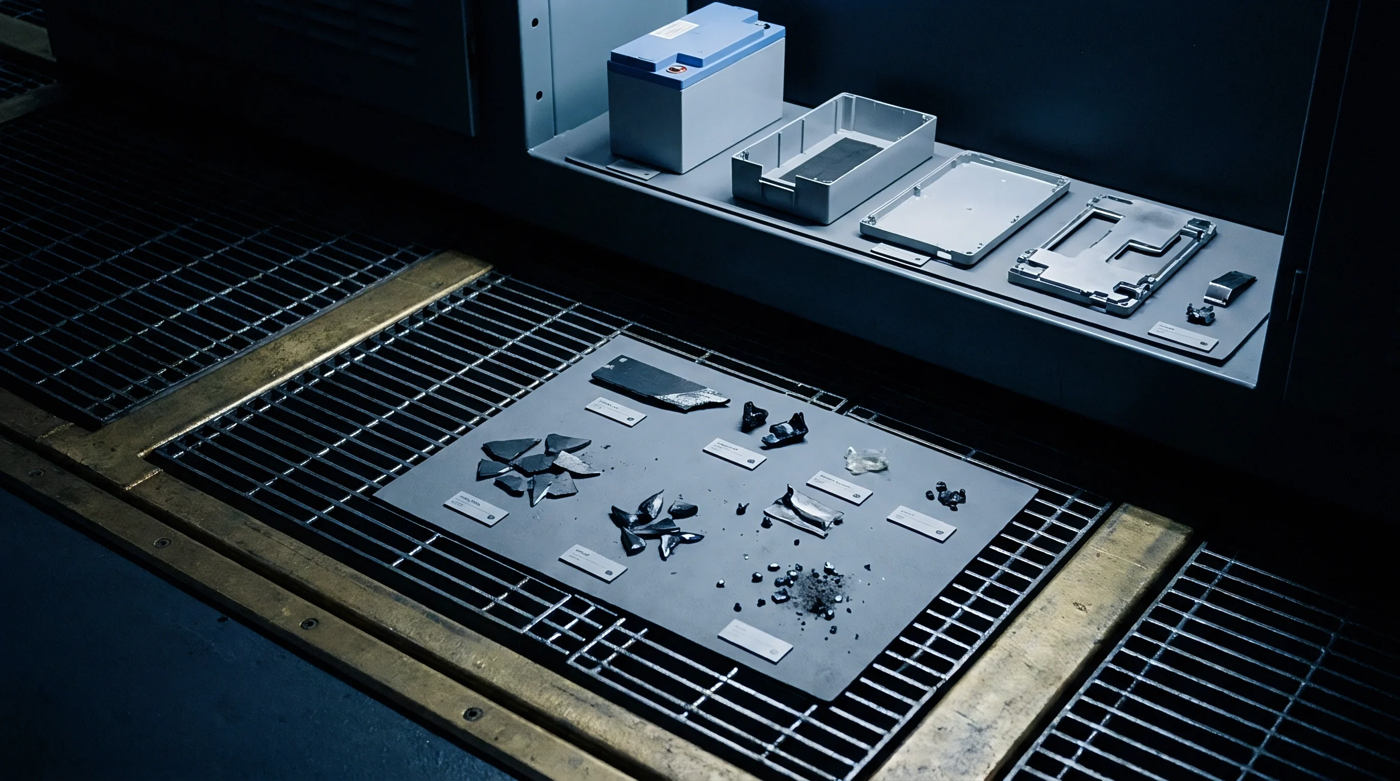
Selecting an enclosure testing architecture for micro-leak rate determination depends on structural dimensions and mechanical pressure constraints. Two principal physical configurations exist for collecting leaked solvent vapors: ambient pressure accumulation testing and direct vacuum extraction testing. Each configuration imposes distinct physical conditions on enclosure seals and demands specific calibration procedures.
Accumulation testing places the sealed battery enclosure inside a rigid test chamber at atmospheric pressure. A recirculating clean sweep gas, typically dry synthetic air or high-purity nitrogen, continuously moves gas through the accumulation volume into a pre-concentrator or direct sampling port of the GC-MS instrument. Alternatively, static accumulation lets solvent vapors leaking from the enclosure accumulate over a fixed duration, after which an aliquot of chamber air is swept into the GC column.
Ambient pressure accumulation prevents physical deformation of thin-walled pouch cell housings or large structural pack lids, making it suitable for evaluating completed battery packs under zero differential pressure.
Vacuum extraction testing encloses the battery housing inside a vacuum-tight chamber evacuated down to pressures below 1 mbar. Leaking solvent vapors vaporize rapidly under reduced pressure and transfer directly into the GC-MS sampling interface or an intermediate cryogenic cold trap. Vacuum extraction increases outgassing rates and accelerates solvent evaporation from internal capillary defects.
However, applying a full vacuum differential introduces structural stress across large enclosure cover plates and polymer gaskets, potentially inducing artificial mechanical gaps or flattening seal interfaces. Vacuum testing protocols must limit chamber depressurization rates to avoid exceeding structural yield thresholds of battery housing walls.

How Does Electrolyte Solvent Background Mask Micro Leaks?
Background contamination inside test chambers presents a major challenge to quantitative micro-leak determination. Sealed battery packs carry exterior surface contamination from cell handling, structural adhesives, sealant outgassing, and thermal interface materials. These non-leak organic sources release volatile species identical to or overlapping with electrolyte solvent fragments, elevating baseline noise levels.
Discriminating true seal defect leakage from surface outgassing requires evaluating time-dependent mass accumulation rates. Surface outgassing follows exponential decay kinetics over time as volatile species desorb from exterior surfaces. True micro-leakage through a structural defect produces a constant, linear accumulation rate over extended test durations once internal vapor pressure reaches steady-state equilibrium.
Plotting mass accumulation (Δ m) against test time (Δ t) allows analytical software to subtract exponential surface outgassing curves from linear defect leak rates.
| Test Parameter | Helium MS Vacuum Method | Fluorocarbon Tracer GC-MS | Direct Solvent Vapor GC-MS | Pressure Decay Method |
|---|---|---|---|---|
| Target Molecule | Helium (He) | R-134a / HFO-1234yf | DMC / EMC / DEC | Air / Nitrogen |
| Detection Threshold (mbar·L/s) | 10^-9 to 10^-10 | 10^-7 to 10^-8 | 10^-8 to 10^-9 | 10^-3 to 10^-4 |
| Flow Regime Sensitivity | Molecular flow dominance | Transition regime | Molecular & viscous transition | Viscous flow only |
| Surface Background Noise | Very low (ambient He ~5 ppm) | Low (synthetic tracer) | Moderate to high (outgassing) | Zero (pressure drop based) |
| False Positive Susceptibility | High (elastomer permeation) | Low | Low (GC peak separation) | High (thermal drift) |
| Enclosure Stress Level | High (requires full vacuum) | Low to moderate | Zero to low (ambient option) | Moderate (positive pressure) |
Maintaining chamber cleanliness relies on continuous high-temperature thermal bakeout cycles between testing runs. Accumulation chambers constructed from electro-polished 316L stainless steel feature low surface adsorption coefficients for polar organic vapors. Heating chamber walls to 80 degrees Celsius under high-vacuum purge between sample cycles removes residual carbonate molecules desorbed during prior test runs.
- Thermal bakeout cycles executed at 80 degrees Celsius under vacuum remove desorbed carbonate solvent residues from internal stainless steel chamber surfaces.
- Linear accumulation rate tracking separates continuous defect leak paths from decaying surface outgassing profiles over 60-minute test intervals.
- Cryogenic pre-concentration traps chilled to minus 40 degrees Celsius capture trace solvent vapors from high-flow sweep gases prior to thermal desorption into the GC column.
- Differential pressure regulation maintains zero pressure drop across enclosure covers during ambient accumulation to prevent mechanical seal deformation.
Determining whether ambient temperature variations during 12-hour static accumulation runs distort linear slope calculations through thermal expansion of gas volumes remains an open operational question for high-volume pack testing facilities.

Dossier

Transport Safety Frameworks and Certification Proof
Cross-border transport of lithium-ion batteries requires proving structural integrity under extreme environmental conditions. International dangerous goods regulations dictate mandatory test protocols that battery cells, modules, and packs must pass prior to commercial shipment. Micro-leak determination serves as key analytical evidence proving that cell seals withstand transport stresses without releasing hazardous materials.
The UN Manual of Tests and Criteria, Section 38.3, mandates a series of mechanical and environmental challenges. Test T.4 (Altitude Simulation) subjects fully charged batteries to an ambient pressure of 11.6 kPa or less for a minimum of six hours at 20 degrees Celsius. This pressure drop creates an internal-to-external pressure differential exceeding 89 kPa across enclosure joints.
Test T.5 (Thermal Test) subjects units to temperature extremes ranging from minus 40 degrees Celsius to plus 72 degrees Celsius, repeating cycles ten times with maximum thermal transition rates. Passing UN 38.3 criteria requires demonstrating no mass loss, no leakage, no venting, and no disassembly. Standard physical inspection or mass balance weighing lacks the sensitivity to detect micro-gram solvent loss during altitude simulation; quantitative GC-MS analysis provides verifiable quantitative proof of seal integrity for dangerous goods declaration files.
International standard IEC 62133-2 defines safety requirements for portable sealed secondary lithium cells and batteries. Clause 7.3.2 evaluates seal integrity during extended thermal cycling under moisture-controlled conditions. The European Battery Regulation (EU) 2023/1542 expands compliance duties by establishing mandatory carbon footprint disclosures, supply chain due diligence, and performance durability criteria.
Annex VIII of the EU regulation mandates performance metrics including capacity retention and internal resistance stability over service lifespans. Micro-leakage of electrolyte solvent leads to electrolyte drying, capacity loss, and accelerated internal resistance increase. Documenting micro-leak rates below 10-7 mbar·L/s within technical dossiers validates 10-year durability claims under European market access rules.

Safety Dossier Structure and Audit Verification
A compliant dangerous goods safety file links raw GC-MS analytical outputs directly to certified test items. Freight forwarders, aviation security inspectors, and national dangerous goods authorities verify test summaries against formal test reports. Missing or unverified calibration data invalidates transport declarations, exposing importers of record to border confiscations and legal penalties.
The technical compliance dossier must maintain a complete chain of traceability from instrument calibration to batch release certificates. A complete safety dossier includes mass spectrometer daily calibration records showing response factor stability, permeation tube gravimetric certification logs, raw chromatographic SIM data files, and background ambient chamber measurement logs. Documenting sample preparation, carrier gas purity grades, and calculated detection limits establishes the legal defensibility of micro-leak determination results during regulatory audits.
Section 38.3.4.4 of the UN Manual of Tests and Criteria defines transport leak failure as any physical electrolyte release exceeding 0.1 percent of total initial cell mass.
Relying on simple gross mass measurements to verify UN 38.3 compliance introduces major regulatory risk. A 50-gram pouch cell losing 49 milligrams of volatile electrolyte solvent during altitude testing passes the gross mass threshold of 0.1 percent (50 mg), yet releases sufficient flammable solvent vapor to ignite inside sealed cargo containers. Quantitative GC-MS micro-leak testing identifies mass loss down to sub-microgram levels, resolving compliance gaps left by coarse gravimetric balances.
According to UN Manual of Tests and Criteria Section 38.3.5, the mandatory Lithium Battery Test Summary must state explicitly: “This document certifies that the cell or battery enclosure has been verified leak-tight under altitude simulation Test T.4 using calibrated mass spectrometry with a demonstrated detection limit not exceeding 1.0 x 10^-6 mbar L/s.”


Stipulation

Commercial Contracts and Defect Threshold Allocation
Commercial agreements between battery cell manufacturers, module pack integrators, and original equipment manufacturers require explicit technical clauses defining allowable micro-leak thresholds. Vague terms such as “hermetically sealed” or “leak-free” lack legal definition and invite dispute during warranty claims. Quality agreements specify quantitative leak rate limits (mbar·L/s), standard reference test gases, target solvent mass channels, and accepted calibration protocols.
Defining acceptable micro-leak rates balances manufacturing yield costs against long-term field failure risk. Setting an enclosure leak rate specification at 10-8 mbar·L/s prevents solvent loss and moisture ingress over a 15-year automotive service life. However, enforcing this limit across high-volume automated assembly lines increases scrap rates and inspection equipment costs.
Conversely, relaxing leak specifications to 10-5 mbar·L/s lowers manufacturing inspection costs while allowing moisture ingress rates that generate hydrofluoric acid (HF) inside cells, accelerating capacity fade and cell degradation.
Contracts establish formal incoming quality limits (AQL) using sampling protocols governed by ISO 2859-1. Receiving inspection protocols for cell batches define normal, tightened, and reduced sampling plans based on historic vendor quality history. When incoming sample lots undergo GC-MS micro-leak verification, discovering a single unit exceeding the specified upper critical leak limit (UCLleak) triggers lot rejection protocols, placing quarantine obligations on the supplier.

Liability Boundaries and Risk Allocation Clauses
Quality agreements allocate warranty exposure based on empirical micro-leak determination. If field failure analysis attributes cell degradation or thermal events to moisture ingress through defective cover welds, calibrated GC-MS records established at batch acceptance determine liability boundaries. Proving that cells met micro-leak specifications at the time of delivery shifts financial responsibility for field failures onto the pack integrator’s thermal management or structural pack design.
Contracts relying on coarse pressure decay testing (10-3 mbar·L/s threshold) yield a 14 percent higher incidence of disputed warranty claims tied to premature capacity degradation than those enforcing quantitative GC-MS solvent leak testing (10-7 mbar·L/s threshold). Precise measurement criteria eliminate ambiguity during warranty cost recovery arbitration.
Importers of record bear sole legal responsibility for regulatory compliance, environmental liabilities, and dangerous goods transport compliance under EU Battery Regulation 2023/1542 and US DOT Hazardous Materials Regulations. Purchasing uncertified cells without verified GC-MS micro-leak calibration dossiers exposes importing entities to strict liability enforcement, including mandatory market recalls, transport bans, and commercial insurance exclusions.
Structuring supply contracts with mandatory supplier-side GC-MS micro-leak verification dossiers protects buyers against incoming batch defects. Receiving inspection protocols execute quantitative SIM ion sweeps on representative batch samples to confirm seal integrity before components release into module assembly streams.