Designing Spring Pack Compliance Modules for High Capacity Solid State Pouches
Dynamic spring pack compliance modules maintain prescribed stack pressure across pouch expansion to preserve solid electrolyte interfaces and prevent cell failure.
Pressure
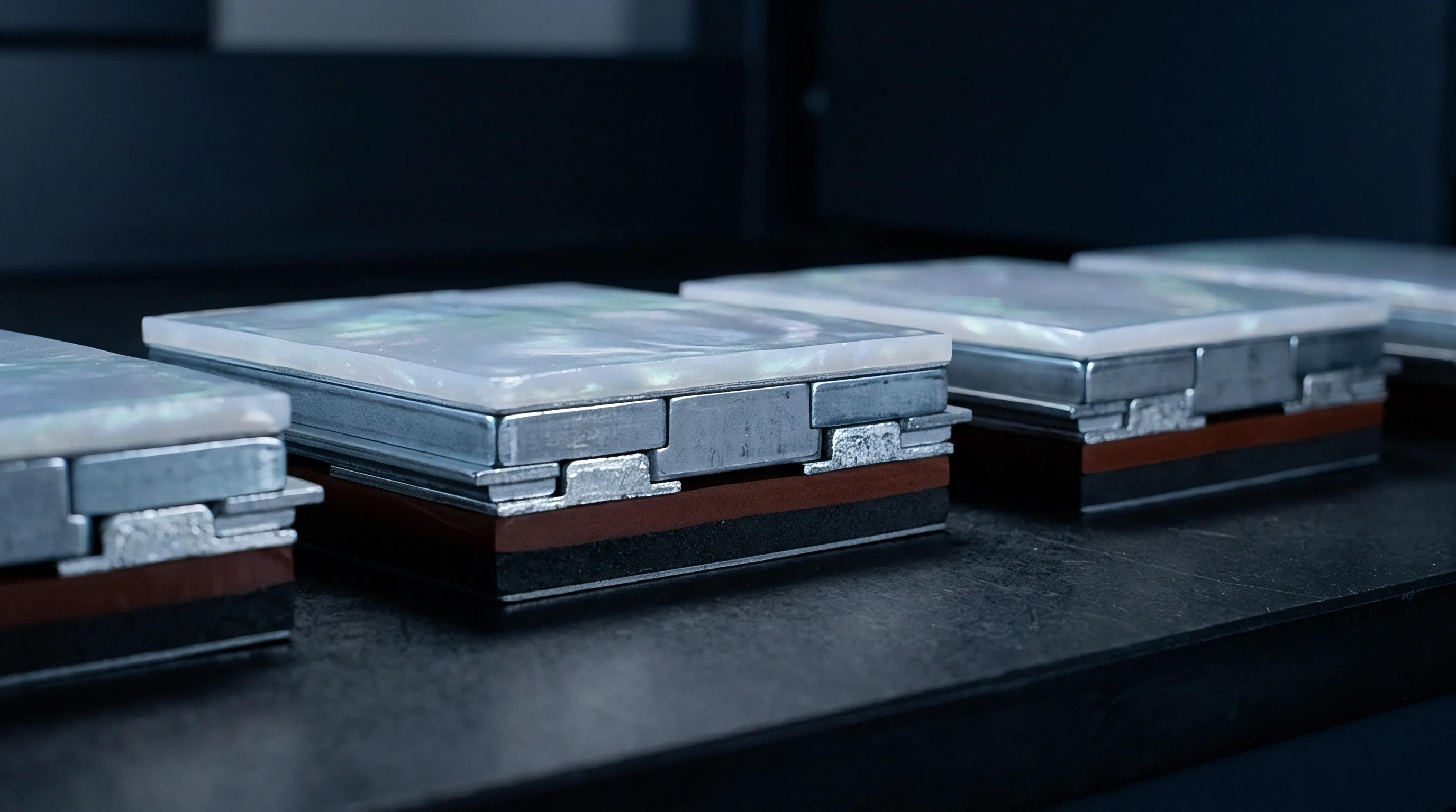
Solid-state pouch cells using sulfide or oxide electrolytes require continuous mechanical clamping through every charge and discharge cycle. As lithium deposits at the anode interface during lithiation or silicon expands, cell thickness increases by five percent to over fifteen percent depending on the active material formulation. Without sufficient external restraint, micro-cavities open at the solid electrolyte interface, leading to localized impedance spikes, current crowding, and early lithium dendrite growth.
Uneven contact pressure causes rapid degradation in sulfide electrolytes.
Maintaining physical contact between rigid solid electrolyte particles and active materials requires uniform external compressive force. In high-capacity pouch formats between twenty and one hundred ampere-hours, surface areas exceed three hundred square centimeters, which scales up the total expansion force. If cell thickness increases during charging within a rigid enclosure that lacks compliance mechanisms, internal stress can exceed twenty megapascals, rupturing the pouch casing or fracturing the ceramic separator.
Maintaining a continuous uniform compressive load between one and four megapascals across all operational state-of-charge levels suppresses interfacial void formation in sulfide-based solid state pouches.
Dynamic compression systems buffer these dimensional shifts, keeping forces above minimum contact thresholds even at full discharge. Designing a mechanical compliance module means balancing the initial assembly preload against maximum expansion force at full state of charge and late-life cell swell. Determining total displacement requires accounting for pristine stack dimensions, manufacturing thickness tolerances, solid electrolyte expansion coefficients, and separator creep over thousands of deep cycles.
Gaps under sub-MPa pressure create prime sites for lithium metal dendrite nucleation.
Operating temperature swings and differing thermal expansion coefficients alter the required minimum clamping force across extreme winter and summer duty cycles.

Spring
Mechanical compliance elements inside solid-state battery modules absorb volumetric expansion while holding clamping forces within strict limits. Building elastic structural components directly into cell holding frames lets the pack geometry adapt dynamically as charge shifts. Choosing the right spring geometry involves balancing available envelope space, required stroke distance, load-deflection linearity, and total mass budget.

Compliance Element Architectures
Belleville washer disc spring stacks provide high force capacity in short axial lengths. Stacking Belleville washers in series increases stroke length while keeping output force constant, whereas parallel stacking multiplies load capacity at the original deflection range. Wave springs made from flat crested wire reduce axial height by up to fifty percent relative to round wire coil springs while matching linear force profiles across the working compression range.
Belleville washers inherently deliver very high spring rates.
Elastomeric compression pads made from fluorosilicone or microcellular polyurethane foam distribute surface loads evenly, but they exhibit non-linear force curves and relax under long-term strain. Under steady pressure at higher temperatures, synthetic elastomers take a permanent set, causing residual clamping force to drop below minimum thresholds over time. By contrast, spring steel Belleville stacks and stainless steel wave spring modules retain mechanical force over ten-year operating lives without thermal creep.
| Compliance Mechanism Type | Pressure Range (MPa) | Stroke Capacity (mm/cell) | Creep Susceptibility | Mass Density Index |
|---|---|---|---|---|
| Belleville Washer Series Stacks | 1.5 to 6.0 | 0.3 to 1.2 | Negligible | High |
| Nested Flat-Wire Wave Springs | 0.8 to 4.5 | 0.5 to 2.5 | Low | Medium |
| Microcellular Polyurethane Pads | 0.2 to 1.8 | 1.0 to 4.0 | Severe above 50C | Low |
| Helical Coil Side-Link Assemblies | 0.5 to 3.0 | 2.0 to 6.0 | Negligible | High |
Force Deflection Dynamics across State of Charge
Silicon-containing anodes expand by more than twelve percent at full charge.
Matching the spring rate to cell expansion behavior stabilizes stress across the module. If the spring rate is too high, internal pressure spikes during charging, which cracks cathode particles and accelerates electrolyte breakdown. If it is too soft, the required travel distance increases, taking up pack volume and growing the enclosure footprint.
- Spring fatigue fracture occurs when repeated mechanical flexing exceeds the endurance limit of high-stress metallic alloys during continuous charge-discharge cycles.
- Localized force concentrating happens when non-parallel deflection of spring guide rods tilts compression plates, creating severe stress gradients across the pouch surface.
- Thermal relaxation loss develops when temperature spikes reduce yield strength in low-grade carbon steel Belleville washers, lowering baseline clamping force through permanent set.
- Abrasive plating wear emerges from unlubricated sliding along spring guide surfaces, shedding conductive metal debris inside high-voltage enclosure spaces.
Module mechanical designs aim for spring compliance curves that flatten at high deflections, absorbing expansion without pushing interface pressure beyond structural limits.

Stack
Dimensional variations across multi-cell pouch stacks dictate the baseline preload set by rigid end platens. Cumulative pouch thickness tolerances create wide variation in total uncompressed stack length across production runs. Consequently, assembly fixturing relies on applied force rather than fixed mechanical displacement to set tie-rod and frame latch positions.
Platen Rigidity and Deflection Limits
End plates tend to bow when subjected to localized forces.
Flexure in module end plates shifts clamping force toward the pouch edges while relieving pressure across the central active area. Finite element analysis guides ribbing patterns and wall thickness to keep bending deflection under fifty micrometers at peak expansion loads. Cast aluminum alloys like A356-T6 offer lightweight bending resistance, while structural stainless steel plates deliver higher stiffness in tighter envelopes.
According to structural bending standards for battery enclosures, maximum platen center deflection under full operational load must not exceed 0.05 millimeters per 100 millimeters of span distance.
Worked Calculation for Twenty Cell Module Compliance
To illustrate stack mechanics, consider a twenty-cell stack using sulfide-electrolyte high-energy pouches. Each pristine cell measures 12.00 mm in nominal thickness with a tolerance of plus or minus 0.15 mm. Nominal uncompressed stack thickness is 240.0 mm, spanning an envelope from 237.0 mm to 243.0 mm across production lots.
Each pouch has an active area measuring 180 mm wide by 250 mm long, giving 45,000 square millimeters (0.045 m²) of contact surface. Target surface pressure is 2.0 MPa at 0% state of charge and must remain under 4.5 MPa at 100% state of charge. Generating 2.0 MPa across this surface requires an initial preload force of 90,000 Newtons (90 kN).
Cell swelling measurements show an 8 percent linear thickness expansion per pouch at full lithiation, or 0.96 mm per cell. Across twenty cells, total stack expansion reaches 19.2 mm between fully discharged and fully charged states. Factoring in manufacturing tolerances adds plus or minus 3.0 mm, bringing the total compliance travel budget to 22.2 mm.
| State of Charge (%) | Cell Expansion (mm/cell) | Total Stack Swell (mm) | Min Stack Force (kN) | Max Stack Force (kN) | Nominal Surface Pressure (MPa) |
|---|---|---|---|---|---|
| 0 (Fully Discharged) | 0.00 | 0.00 | 76.5 | 103.5 | 2.00 |
| 25 | 0.24 | 4.80 | 98.2 | 127.4 | 2.51 |
| 50 | 0.48 | 9.60 | 119.8 | 151.2 | 3.01 |
| 75 | 0.72 | 14.40 | 141.5 | 175.1 | 3.52 |
| 100 (Fully Charged) | 0.96 | 19.20 | 163.2 | 198.9 | 4.02 |
Configuring the wave spring pack with a combined spring rate of 3.8 kN/mm absorbs the 19.2 mm swell with a reaction force increase of 72.96 kN. Added to the 90 kN baseline preload, the total force at full charge reaches 162.96 kN, producing a peak surface pressure of 3.62 MPa on nominal stack dimensions ~ well below the 4.5 MPa limit.
Variations in stack thickness directly alter the initial assembly preload.
- Planar parallelism mapping verifies that top and bottom platen faces stay within 0.08 millimeter parallelism under full 180 kilonewton loads.
- Corner stiffness profiling measures platen displacement under asymmetric corner loading to prevent edge pinching during rapid swelling.
- Rib deflection scanning uses optical laser profilometry to map internal rib bowing under maximum force loading.
- Fastener torque stability measures tension retention on tie rods following thermal shock exposure between negative forty and eighty-five degrees Celsius.
Uncontrolled end plate bending drops pressure across the center of the stack, accelerating delamination at the solid electrolyte interface and degrading capacity in central cells.

Sleeve
Module enclosures housing spring-loaded cell stacks must balance mechanical restraint, electrical isolation, and heat dissipation. Cell tabs exit the sleeve housing through sealed dielectric grommets that block moisture while accommodating axial expansion during charging.
Interface Materials under Continuous Clamping
Thermal interface pads tend to cold-flow when kept under sustained pressure.
Compressible dielectric thermal interface materials placed between pouch faces and compression platens carry heat laterally to external cooling plates. However, continuous pressure squeezes silicone or ceramic-filled pad material out of the active contact zone. As the pads thin, dielectric breakdown voltage drops and baseline stack dimensions change.
Continuous mechanical compressive stress above two megapascals accelerates elastomeric cold-flow extrusion, diminishing dielectric breakdown safety margins across high-voltage cell stacks.
| Material Formulation | Initial Thickness (mm) | Thickness at 2.0 MPa (mm) | Thermal Impedance (K-cm²/W) | Dielectric Strength (kV/mm) |
|---|---|---|---|---|
| Fibreglass Reinforced Silicone Pad | 1.50 | 1.28 | 1.15 | 12.0 |
| Cross-linked Boron Nitride Elastomer | 1.00 | 0.72 | 0.85 | 15.5 |
| Phase-Change Polyolefin Matrix | 0.50 | 0.28 | 0.42 | 8.0 |
| Synthetic Acrylic Thermal Gel | 2.00 | 0.85 | 0.65 | 10.5 |
Dielectric Isolation and Creepage Clearance Spacing
Material creep gradually reduces initial bolt clamping forces.
High-voltage modules operating above four hundred volts require defined creepage and clearance distances inside spring compliance envelopes. Sliding parts, guide pins, and metallic Belleville springs are isolated from live pouches using engineering thermoplastics like polyetheretherketone or polyphenylene sulfide. As pouches expand, shifting tab positions create cyclic bending stresses at copper tab welds, requiring flexible leaf-laminated busbar links.
Unexpected pressure drops often result from cell swelling rates exceeding the nominal specification sheet limits set during initial module architecture design.


Bench
Validation protocols for dynamic clamping hardware measure mechanical fatigue alongside electrical performance during extended thermal cycling. Test benches simulate cell breathing while controlling force, displacement, and environmental temperature.

Dynamic Pressure Sensor Performance in Endurance Testing
Tactile pressure mapping sensors built into test stacks suffer from gauge factor drift and substrate breakdown under sustained pressure and heat. Thin-film piezoresistive arrays lose calibration after fifty thousand expansion cycles at sixty degrees Celsius. Placing permanent load cells under tie rod nuts on the end platens provides reliable, long-term force measurements without disturbing thermal contact surfaces.
Vibration testing significantly accelerates fatigue in spring components.
Mechanical Fatigue and Vibration Testing
Module compliance assemblies are subjected to multi-axis random vibration profiles while holding maximum static preloads. Mechanical lock integrity, spring sleeve endurance, and tie rod thread shear limits are tested with shock loads reaching fifty gravities under dynamic resonance.
Dynamic force-displacement calibration follows this test sequence during first-article inspection:
- Mount the fully assembled compliance module onto the servo-hydraulic test fixture frame.
- Connect primary load cells and laser displacement sensors to real-time data acquisition channels.
- Apply baseline assembly preload force up to ninety kilonewtons at a rate of 0.5 millimeters per minute.
- Cycle the transducer through nineteen point two millimeters of simulated pouch expansion stroke for one thousand pre-conditioning loops.
- Record load-versus-stroke hysteresis curves at chamber temperatures of negative twenty, twenty-five, and sixty degrees Celsius.
- Measure residual compression set and mechanical deformation on spring guide elements using optical coordinate measurement machines.
Module housing dimensions drift measurably during extended thermal cycling.
Under UN 38.3 transport testing standards, dynamic compliance modules must maintain structural clamp force without physical rupture, shorting, or loss of insulation after twelve hours of sinusoidal sweep vibration from seven to two hundred Hertz.

Tariff
Commercial agreements for spring compliance modules split financial obligations between non-recurring tooling engineering fees and long-term warranty reserves. Tooling capital expenditure for precision dies, wave spring forming tools, and aluminum end-plate casting molds requires substantial upfront investment prior to production validation.
Non Recurring Engineering and Tooling Amortization
Tooling costs scale directly with the geometric complexity of end plates.
High production volumes amortize tooling expenses across hundreds of thousands of pack modules, reducing compliance hardware costs to a small fraction of the total bill of materials. Low-volume programs face steep per-unit costs unless they use standardized Belleville washer sizes and off-the-shelf structural extrusions.
Commercial contracts assign primary module tooling amortization across the initial fifty thousand production units, after which piece-part supply pricing steps down by thirty-five percent.

Warranty Boundaries between Cell and Module
Warranty responsibility boundaries usually divide at the module flange interface.
Clear liability boundaries between cell suppliers and pack assembly vendors prevent disputes when batteries lose capacity in service. If a cell fades prematurely from uneven contact pressure, pinpointing whether the root cause lies in cell gas evolution or spring relaxation requires forensic teardown and historical data from embedded BMS force sensors.
- Cell expansion limit specification defines maximum allowable pouch swell before spring force changes void supplier performance guarantees.
- Spring relaxation rate thresholds set acceptable mechanical preload decay limits over ten-year operating periods under specified thermal envelopes.
- Thermal interface pad creep limits dictate maximum allowable thickness loss before module assembly warranties shift to pad material manufacturers.
- Fastener torque decay caps set minimum thread retention force levels required following transit shock and operational vibration exposure.
Spring fatigue gradually reduces stack clamping force over time.
Contractual responsibility for module structural integrity transfers from the pack assembly partner to the vehicle manufacturer once the battery enclosure passes receiving quality audits at the assembly plant.