Dynamic Load Compliance Calibration Methods for High Pressure Battery Module Compression Test Tooling
Dynamic compliance calibration corrects structural fixture deflection in high-pressure battery compression tooling, ensuring exact cell expansion force data.
Frame
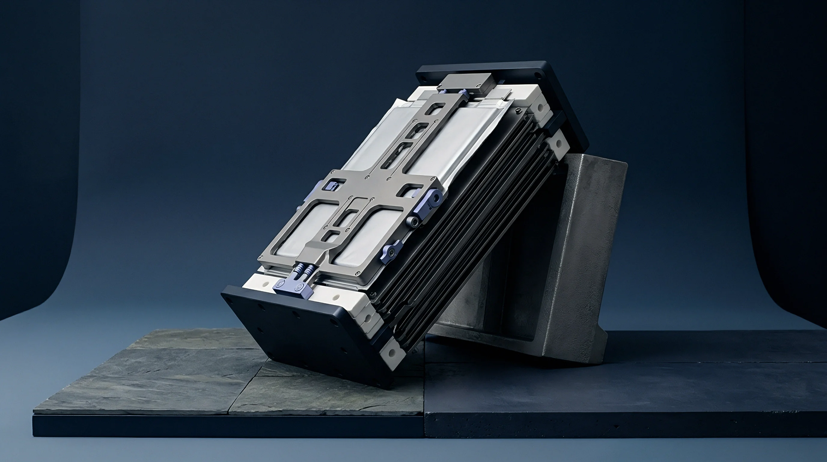
High-pressure compression testing of lithium-ion battery modules subjects mechanical tooling to cyclic loads up to 100 kilonewtons. Module expansion during fast charging and thermal degradation generates internal swelling forces that push against boundary platens. When a compression rig experiences mechanical deflection, the recorded force-displacement curve represents the combined compliance of both the battery module and the surrounding test machine.
Mechanical compliance in tie rods, load platens, hydraulic actuators, and load cell mounting interfaces introduces serious measurement artifacts. Rigidity variations across the loading platen skew pressure distribution over prismatic and pouch cell stacks. Standard static calibration methods fail to capture structural deformation under dynamic loading conditions, where load application rates range from 0.5 kilonewtons per second to over 50 kilonewtons per second during thermal runaway propagation events.
Platen deflection exceeding 0.05 millimeters across a 400-millimeter span distorts localized cell pressure distribution by more than 18 percent.
Platen bending under high center-loaded forces alters the inter-cell surface pressure profile. Inner cells within a module stack experience higher local restraint than outer cells adjacent to structural tie rods. Standard structural steel platens exhibit non-linear bending moments when loaded above 50 percent of their yield strength.
Upgrading load frames to ultra-high modulus alloy materials reduces geometric deflection, but dynamic load compliance persists within threaded load paths, hydraulic fluid column elasticity, and structural pin joints.
| Component Description | Material Grade | Elastic Modulus (GPa) | Axial Deflection (mm) | Compliance Contribution (%) |
|---|---|---|---|---|
| Structural Tie Rods (4x M30) | AISI 4340 Alloy Steel | 210 | 0.142 | 38.5 |
| Upper Load Platen (60mm thick) | Tool Steel P20 | 205 | 0.088 | 23.9 |
| Hydraulic Actuator Fluid Column | ISO VG 46 Hydraulic Oil | 1.5 (Bulk Modulus) | 0.095 | 25.8 |
| Load Cell Mount & Spherical Joint | 17-4 PH Stainless Steel | 196 | 0.044 | 11.8 |
Characterizing the total load-frame stiffness matrix requires measuring structural displacement directly along the load axis under controlled force gradients. Static stiffness values obtained from dial indicators under static press conditions fail to reflect dynamic rigidity. Dynamic load compliance includes time-dependent structural settle, elastomeric seal deformation inside hydraulic cylinders, and transient frame resonance.
Uncorrected force data collected during rapid cell swelling understates peak module swelling stress, leading to undersized module clamping structures in final pack assemblies.
Sensor
Load measurement in high-pressure battery module compression rigs depends on force transducer design and sensor placement within the force chain. Piezoelectric, piezoresistive, and strain-gauge force sensors react differently to dynamic stress inputs. Static force sensors installed outside the primary load loop register delayed force signals due to mechanical dampening across intermediate mechanical joints.
Static loads mask dynamic frame motion.
Thermal coupling between expanding battery modules and load transducers creates thermal drift signals that mask mechanical force inputs. High-rate charge-discharge cycles elevate module surface temperatures to 65 degrees Celsius. Heat transfers through platens into strain-gauge load cells, causing thermal expansion of sensor substrates and output drift.
Dynamic thermal isolation barriers constructed from glass-mica composite or zirconia ceramics minimize conductive heat transfer while maintaining high axial compressive stiffness above 30 gigapascals.
- Transducer Selection ~ Piezoelectric force sensors handle fast dynamic transient loads during cell thermal events, while piezoresistive foil gauges measure long-term static pre-loads during continuous cycling.
- Parasitic Load Isolation ~ Flexure-guided loading heads eliminate off-axis shear forces and bending moments caused by non-uniform cell swelling across the module surface.
- Thermal Barrier Integration ~ Ceramic insulating plates placed directly between the thermal conditioning platen and the force transducer reduce thermal drift to under 0.02 percent full scale per degree Celsius.
- Bandwidth Matching ~ Sensor signal conditioning electronics require sampling frequencies at least ten times higher than the highest dynamic frequency component of the module swelling wave.
Sensor phase delay distorts dynamic force records when tracking high-speed cell volume changes. Strain gauge bridge networks paired with low-pass analog filters introduce phase shifts at force change frequencies above 5 Hertz. Load cell housing deformation under maximum force capacity introduces non-linearity, which calibration software must separate from cell stack mechanical behavior.
Static calibration certificates generated on deadweight test rigs do not reflect dynamic operational accuracy, as host fixture mountings introduce structural hysteresis under live test line conditions.

Profile
Dynamic compression testing requires force application profiles that mirror real-world battery module swell kinematics. Battery swelling operates across distinct timescales. Long-term electrochemical swelling occurs over hundreds of charge-discharge cycles at strain rates below 10-5 s-1.
Rapid swelling occurs during high-C rate fast charging, where lithium intercalation gradients drive volume expansion within minutes. Thermal runaway reaction fronts trigger localized volumetric gas expansion within milliseconds.
What Load Rates Induce Mechanical Deflection Errors?
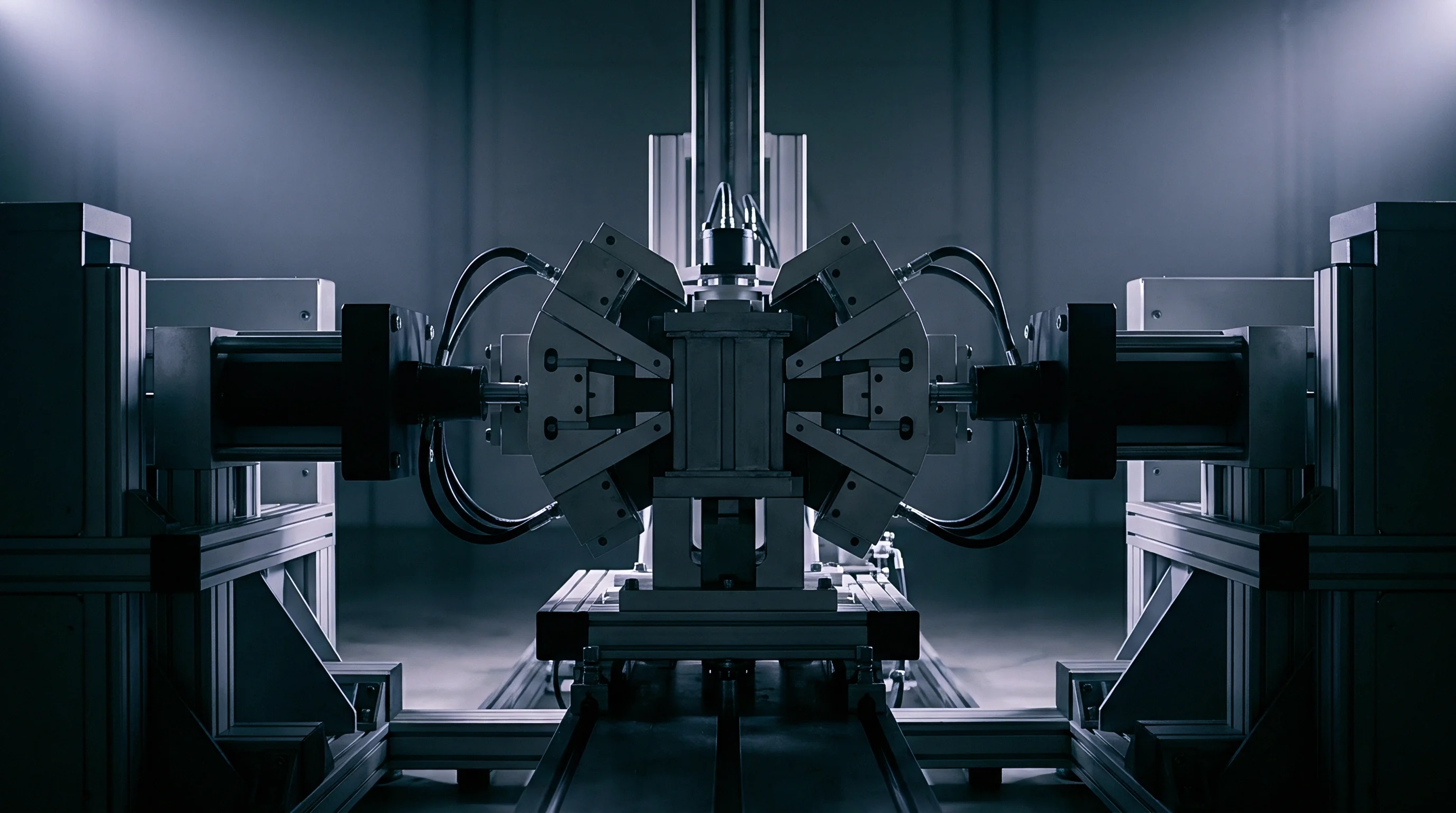
Dynamic compliance errors scale with the rate of load change (mathrmdF/mathrmdt). When force application rates exceed 5 kilonewtons per second, structural inertia inside the test frame generates load overshoot. Hydraulic systems exhibit fluid compressional lag.
Electric screw driven platens experience spindle torsional flex under sudden acceleration. Dynamic profiles must balance velocity inputs to prevent mechanical ringing while maintaining target compression rates on the battery stack.
Intercalation-driven breathing loads exhibit distinct force-displacement hysteresis loops during charge and discharge phases. Uncorrected frame deflection distorts the area inside these hysteresis loops, altering calculated mechanical energy dissipation values. The physical stiffness of the module increases non-linearly as density rises during high state-of-charge states.
Load frame compliance softens the effective boundary stiffness experienced by the cells, allowing greater physical expansion than would occur inside a rigid cast-aluminum pack enclosure.
Dynamic compliance calibration reduces force measurement hysteresis errors from 14 percent down to less than 1.2 percent across a 80 kilonewton dynamic cycle.
Continuous dynamic breathing profiles apply sinusoids or ramp functions superimposed on a static baseline pre-load. Module pre-load values typically sit between 2 kilonewtons and 15 kilonewtons depending on cell chemistry and pouch format constraints. Dynamic load amplitude can reach 40 kilonewtons above pre-load.
Calibration routines must prove force control accuracy across both low-force pre-load regimes and high-force peak compression domains without changing control gain parameters.
The unresolved boundary problem remains whether dynamic calibration methods should model variable platen tilt under asymmetrical cell swelling, or if mechanical flexure guides should strictly force platens to stay parallel under all loading conditions.
Tare
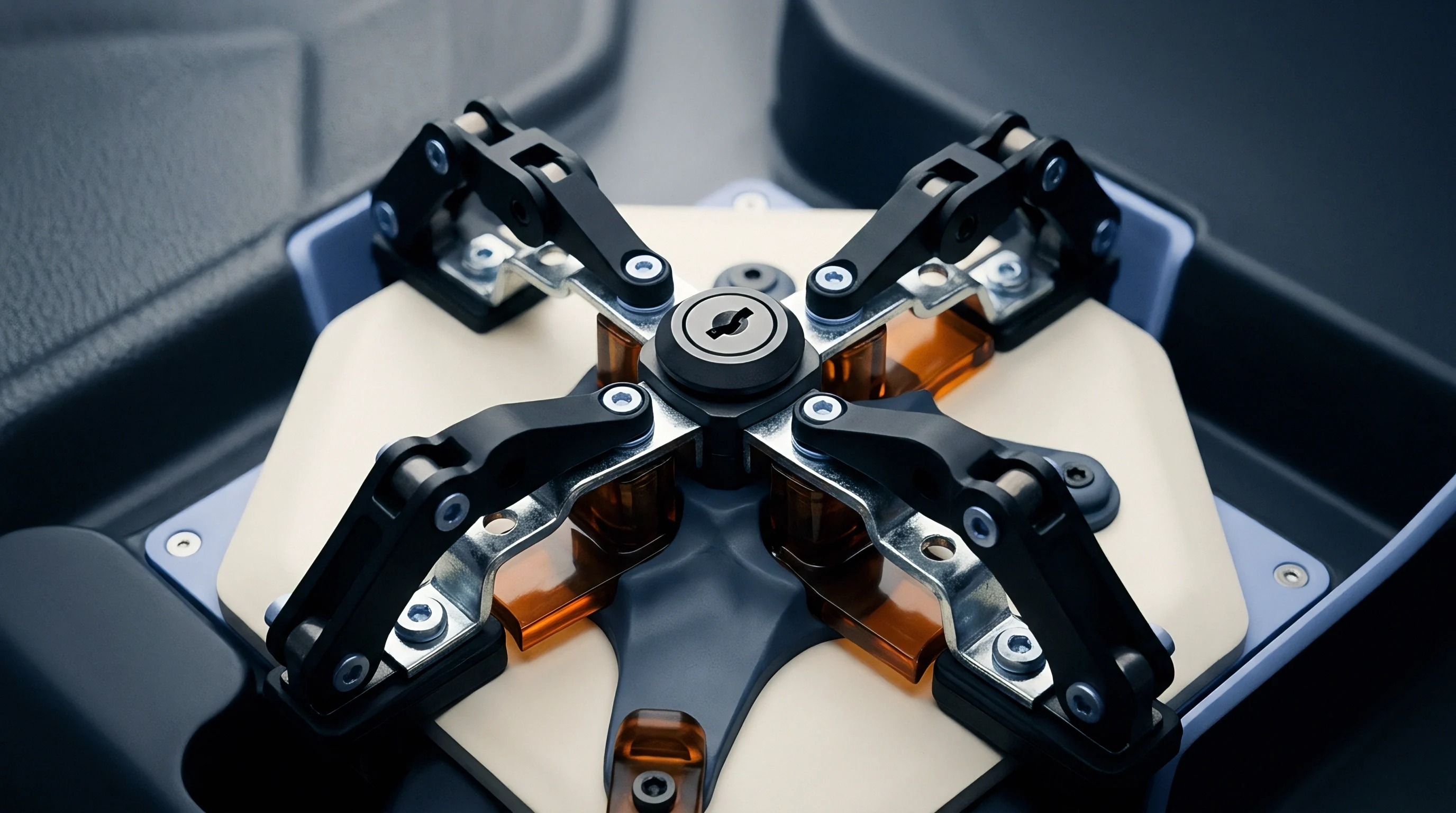
Subtracting rig compliance from raw measurement data requires mathematical extraction of the frame transfer function. Raw displacement sensor signals combine actual cell stack deformation with elastic strain across all test fixture structural elements. Isolating cell performance demands real-time dynamic compensation algorithms running inside the test controller loop or rigorous post-processing mathematical subtraction.
Frame compliance behaves as a force-dependent non-linear spring network. Total measured system displacement (Xsystem) equals the sum of module displacement (Xmodule) and frame compliance displacement (Xframe). The frame deflection term functions as a non-linear function of applied load (F) and rate of load application (mathrmdF/mathrmdt):
Xsystem(t) = Xmodule(t) + Xframeleft(F(t), fracmathrmdFmathrmdt, Tright)
To construct an accurate compliance tare, empirical calibration runs replace the battery module with a certified, zero-compliance calibration artifact of known mechanical stiffness. A high-rigidity solid forged steel block (Young’s modulus 210 GPa) or an instrumented calibration spring matrix provides a predictable load-displacement response.
The mathematical extraction utilizes a polynomial fitting matrix that calculates frame deformation across discrete force and force-rate points. System controllers use inverse model transfer functions to adjust platen positions dynamically, maintaining true specified displacement boundaries on the battery module during compression testing.
| Compensation Method | Force Range (kN) | Displacement Error (Uncompensated) | Displacement Error (Compensated) | Processing Latency (ms) |
|---|---|---|---|---|
| Static Linear Stiffness Factor | 0 to 20 | 0.120 mm | 0.035 mm | < 0.1 |
| 3rd-Order Force Polynomial Tare | 0 to 60 | 0.280 mm | 0.008 mm | < 0.5 |
| Dynamic State-Space Transfer Function | 0 to 100 | 0.540 mm | 0.003 mm | 2.1 |
| Frequency Domain Hysteresis Model | 0 to 100 (10 Hz) | 0.620 mm | 0.005 mm | 4.5 |
Dynamic state-space compliance models account for structural hysteresis. Load frame joints settle differently during force ramp-up compared to force unloading. Structural compliance calibration matrices must contain separate polynomial coefficients for positive loading trajectories (mathrmdF/mathrmdt > 0) and negative unloading trajectories (mathrmdF/mathrmdt < 0).
Steel platens flex under non-uniform loads. When modules swell unevenly due to localized thermal gradients, single-axis load cells miscalculate net center of pressure. Multi-axis force vector arrays combined with spatially resolved displacement tare maps correct for rotational platen tilt, preventing false elastic modulus calculations for the battery cell stack.
Under ISO 17025 validation guidelines for mechanical testing, laboratory accreditation demands that structural compliance subtraction models explicitly state calculated measurement uncertainty limits across the full dynamic force profile spectrum.
Routine
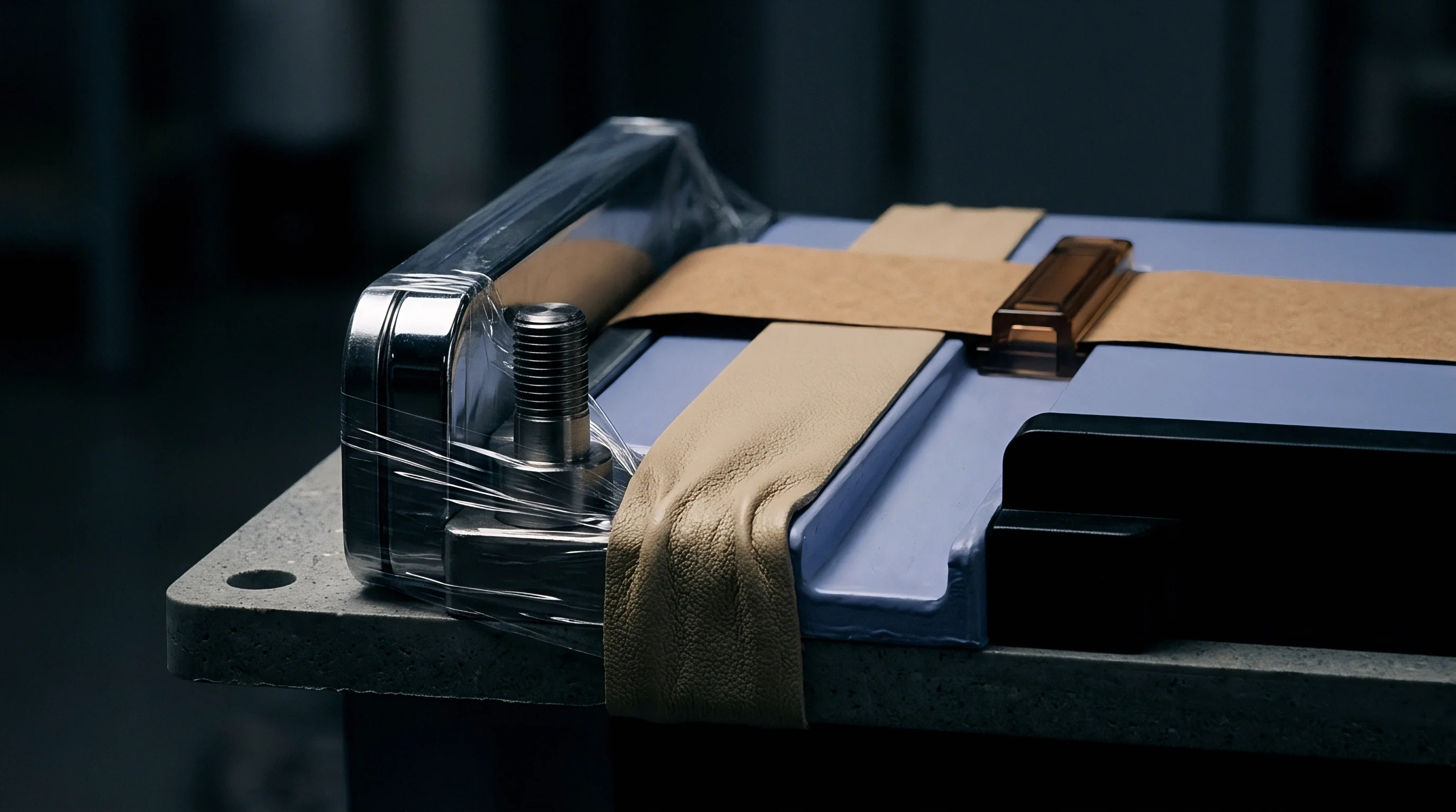
Executing dynamic compliance calibration requires standardized physical procedures and traceable reference hardware. Dynamic calibration replaces static gauge checks with automated multi-step loading sequences. Instrumented calibration artifacts match the physical envelope, mass, and mounting hole configuration of actual battery modules to preserve frame load paths and replicate module stiffness.
Reference spring stacks utilize disk springs (Belleville washers) configured in series and parallel combinations to produce known, stable non-linear force-displacement profiles that simulate dynamic breathing. Calibration technicians preload the artifact within the test machine, applying cyclic force profiles across specified force ranges at varying frequencies. Calibration software records system response curves to update stored tare tables.
Solid steel calibration blocks must be certified via coordinate measuring machines to ensure platen contact parallelism remains under 0.01 millimeters across all loading surfaces.
The calibration routine follows a precise execution sequence to ensure repeatable measurement results across different test channels and operators.
- Mount the certified dynamic calibration artifact centrally between platens to equalize load distribution across frame tie rods.
- Thermalize the complete fixture assembly at 22 degrees Celsius for four hours to eliminate thermal expansion gradients within load frame components.
- Apply three conditioning force cycles from zero to 100 percent maximum rated force to settle mechanical interfaces and eliminate pin joint stack clearance.
- Execute stepped force ramps at application rates of 1, 5, 10, and 50 kilonewtons per second while sampling displacement and force vectors at 10 kilohertz.
- Generate inverse dynamic transfer coefficients and upload updated tare look-up tables directly into the load frame motion controller.
Friction losses distort lower force limits. Linear motion bearings, hydraulic rod seals, and spherical ball joints generate friction force thresholds that must be overcome before platens move smoothly. Dynamic calibration identifies minimum force thresholds where frame movement becomes non-linear due to stick-slip friction behavior.
Calibration intervals rely on total cumulative loaded force cycles rather than standard calendar time, trigger recalibration whenever frame tooling experiences structural overload events or major component service.
Ledger
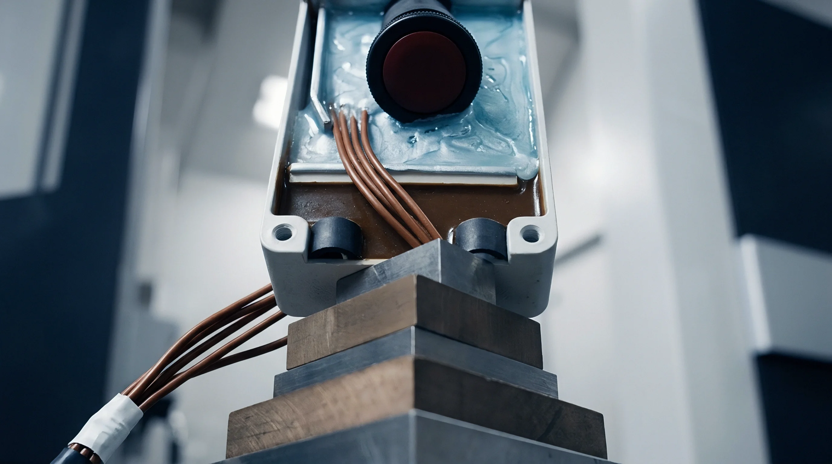
Tooling compliance calibration impacts capital expenditure, production yield, and product safety liability. Submitting uncalibrated module compression test data into battery pack structural designs creates massive financial risk. Overestimating module expansion forces results in overly heavy structural pack enclosures, reducing gravimetric energy density at the vehicle level.
Underestimating module expansion forces causes structural enclosure rupture, mechanical cell deformation, and shortened warranty lifespans in field operations.
Test fixture calibration costs represent a small fraction of overall tooling NRE (Non-Recurring Engineering) expenses. High-pressure dynamic compression test frames command costs between 150,000 USD and 450,000 USD per channel. Advanced dynamic compliance calibration software modules and instrumented reference artifacts add 25,000 USD to 60,000 USD per facility setup.
Fixture calibration frequency directly dictates long-term operating costs.
| Risk Factor / Financial Metric | Uncalibrated Tooling Baseline | Calibrated Dynamic Tooling | Financial Delta Impact |
|---|---|---|---|
| Module Structural Over-design Weight Penalty | +12.5% Pack Case Mass | Nominal Target Mass | 350 USD per vehicle payload penalty |
| Early Cycle Life Module Warranty Claims | 3.8% Return Rate | < 0.2% Return Rate | Estimated 4.2M USD exposure per 10k packs |
| Fixturing Recalibration Annual Cost | 5,000 USD (Basic Static) | 22,000 USD (Dynamic Full Profile) | +17,000 USD Annual Maintenance |
| Module Test Acceptance False Yield Rejections | 4.2% Batch Scrap Rate | < 0.3% Batch Scrap Rate | Savings of 180,000 USD per production line |
Contractual ownership of compliance errors rests with the entity defining the test standard. When a pack integrator specifies cell compression test criteria without dictating dynamic compliance subtraction protocols, cell manufacturers can challenge rejected batches by demonstrating fixture deformation on the buyer’s incoming inspection line. Defining fixture dynamic stiffness tolerances within master supply agreements protects buyers against supplier disputes over cell swelling performance.
Automated calibration logs form an indispensable component of the quality dossier for automotive battery manufacturing. Compliance records must prove that every module lot underwent testing on fixtures calibrated under dynamic loading conditions matched to actual battery swelling rates. The responsibility seam between test rig builders, cell suppliers, and pack integrators ultimately anchors on verified, traceable compliance calibration records that stand up to structural engineering audits.