Decoupling Dynamic Core Temperature Gradients from High Voltage Phase Transitions in Commercial Pouch Formats
Active tab cooling decouples core phase-change heat from pouch surface gradients, extending high-voltage fast-charge cycle life while lowering warranty costs.


Phase
Nickel-rich cathodics operating above 4.35 volts undergo crystalline lattice shearing that generates localized exothermic reaction fronts. Structural degradation inside lithium nickel manganese cobalt oxide cathode structures accelerates as lithium extraction passes sixty-five percent of total capacity. At these state-of-charge thresholds, the planar unit cell contracts rapidly along the crystallographic c-axis, triggering structural conversion from the hexagonal H2 phase to the destabilized H3 phase and liberating enthalpic thermal energy directly within the cathode mass.
Lattice strain manifests unevenly across the thickness of commercial electrodes. Outer electrode layers deintercalate lithium ahead of interior layers during high-rate charging, creating sharp phase boundaries inside a single electrode plate. The localized heat output resulting from the H2-to-H3 transition reaches peak values during constant-current charge steps near the high-voltage cutoff.
Synchrotron diffraction measurements on twenty amp-hour pouch cell samples show a 1.2 percent unit cell volume reduction at 4.35 volts under standard conditions, a value that increases to 2.4 percent when active nickel fractions exceed ninety percent.
| Cathode Chemistry | Transition Voltage Threshold | Lattice Volume Shift | Phase Change Enthalpy | Structural Degradation Mode |
|---|---|---|---|---|
| NMC622 | 4.38 V | -1.1 percent | 14.2 J/g | Microcracking along grain boundaries |
| NMC811 | 4.28 V | -2.1 percent | 28.6 J/g | Intragranular shearing and planar slip |
| NMC900505 | 4.22 V | -2.8 percent | 41.3 J/g | Rapid c-axis lattice collapse |
| LCO | 4.35 V | -1.8 percent | 32.0 J/g | Order-disorder phase transformation |
High-voltage operational windows also accelerate surface oxygen evolution from the cathode lattice. Free radical oxygen released at the cathode interface reacts with carbonate solvents in the liquid electrolyte to initiate parasitic oxidation reactions. This parasitic oxidation generates secondary exothermic heat that adds to the phase-change enthalpy, elevating the total heat flux originating inside the cell active volume.
Structural oxygen release at 4.45 volts under continuous 2C discharge elevates core heat generation by 42 percent compared to standard 4.20 volt operation.
High-voltage capacity loss can stem from electrolyte oxidation rather than cathode lattice shearing.
Lag
Large-format lithium pouch envelopes display severe directional variation in heat transport metrics between their internal layers and outer packaging surfaces. Thin planar geometry creates an intrinsic thermal anisotropy ratio exceeding twenty to one. Thermal conduction along internal current collector foil planes ranges from twenty to thirty watts per meter-kelvin, driven by pure copper and aluminum foil paths.
Cross-plane thermal transport through porous polymer separators, composite cathode coatings, and organic electrolyte fills drops to values between 0.5 and 1.1 watts per meter-kelvin under standard cell compression conditions. Hot-disk thermal constants analyzer measurements at fifty percent state of charge establish a cross-plane conductivity baseline of 0.6 watts per meter-kelvin under 0.3 megapascals stack pressure, rising to 0.9 watts per meter-kelvin when mechanical stack pressure increases to 1.0 megapascal.
During continuous fast charging above two C-rates, internal heat generation overwhelms the cross-plane dissipation capacity of the pouch laminate packaging. The Biot number calculates the ratio of internal conductive resistance to surface convective resistance. When the Biot number exceeds unity, heat accumulates within the central electrode stacks faster than conductive transfer can transport energy to the exterior aluminum packaging film.
| Pouch Cell Format | Thickness | In-Plane Conductivity | Cross-Plane Conductivity | Calculated Biot Number | Core Surface Delta T |
|---|---|---|---|---|---|
| Slim Commercial | 6.0 mm | 28.5 W/(m K) | 0.85 W/(m K) | 0.62 | 4.2 °C |
| Standard Automotive | 10.5 mm | 24.0 W/(m K) | 0.65 W/(m K) | 1.38 | 11.8 °C |
| High Energy Density | 14.0 mm | 21.5 W/(m K) | 0.52 W/(m K) | 2.15 | 18.4 °C |
Exterior thermocouples attached to polymer pouch laminate walls record delayed, heavily damped temperature signals that lag internal jellyroll temperatures by several minutes during transient current spikes. A fifteen degree Celsius gradient between the internal active stacks and the outer packaging pouch routinely develops during aggressive high-voltage fast-charging routines, concealing critical thermal stress from battery management system monitoring algorithms.
- Localized lithium plating occurs at cooler outer electrode edges where kinetic overpotential increases due to lower local thermal conditions during fast charging.
- Separator pore closure accelerates near the innermost cathode layers where continuous thermal retention drives mechanical contraction of polymeric membranes.
- Gas pouch swelling expands polymer laminate packaging when elevated interior temperatures accelerate electrolyte solvent decomposition reactions.
- Current collector fatigue develops from differential thermal expansion strain between hot interior foil sections and cool external tabs.
Active cooling during high-rate discharge may suppress internal crystal phase changes or merely mask surface temperature signals while internal structural decay proceeds unchecked.

Interface
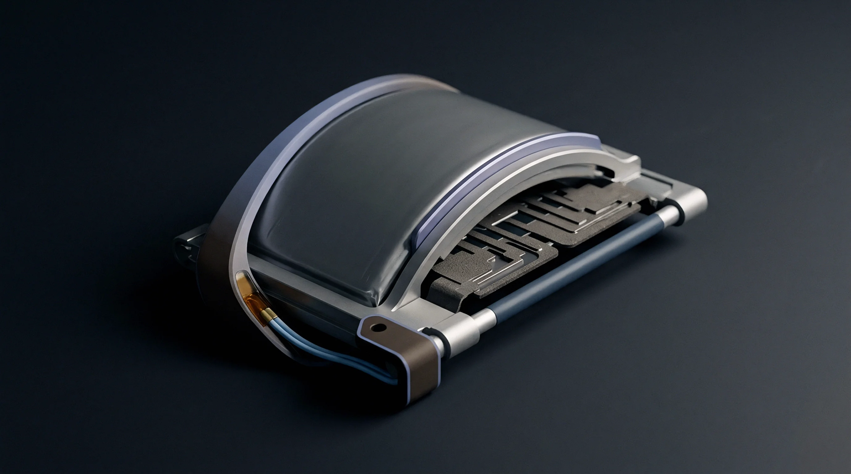
Direct conductive coupling to cell current collector tabs establishes a low-resistance thermal drainage path from interior cathode stacks. Extruded copper and aluminum tabs extend directly from internal foil current collectors, bypassing the low cross-plane thermal conductivity of separator sheets and electrolyte layers. Tab cooling extracts heat parallel to internal foil structures, drawing energy along paths with high thermal conductivity.
High-voltage phase transitions occurring inside electrode stacks release sudden bursts of heat that overwhelm conventional surface-mounted cooling plates, which force thermal energy to cross dozens of insulating polymer layers. Current collectors double as thermal drains. Industrial traction locomotives utilize similar conductive busbar heat extraction methods to cool dense power semiconductor modules operating under megawatt surge loads, demonstrating that heat removal directly through electrical conductors avoids thermal choking inside insulated layers.
Direct heat extraction through tabs suppresses internal thermal gradients more effectively than surface cooling plates because current collectors offer path lengths with lower thermal resistance.
Integrating double-tab architectures with embedded pyrolytic graphite interlayers creates an effective thermal decoupling route. Pyrolytic graphite sheets provide in-plane thermal conductivity exceeding twelve hundred watts per meter-kelvin while maintaining minimal mechanical thickness. Placing these graphite interlayers between individual pouch cells transfers heat rapidly away from internal hot spots toward peripheral heat sinks without adding substantial mass to the module assembly.
- Tab cooling capacity must match peak ohmic heating rates at maximum continuous C-rate to prevent conductive saturation along current collector foil extension necks.
- Interlayer thermal resistance requires evaluation under end-of-life mechanical compression pressure rather than fresh cell bench conditions.
- Busbar joint contact impedance demands low micro-ohm connections to prevent external resistive heat from feeding back into internal electrode stacks.
- Dielectric insulation breakdown voltage across cold plates dictates minimum thermal interface material thickness regardless of heat dissipation performance.
Designing thermal management systems around surface skin readings rather than internal current collector heat flux guarantees premature capacity loss during rapid high-voltage charging.


Probe
Internal diagnostics rely on embedded fiber-optic sensors and high-frequency impedance spectrum tracking to detect thermal differentials inside closed pouch enclosures. Fiber Bragg Grating optical strings positioned directly between cathode-anode doublets measure local thermal expansion and localized temperature variations during high-voltage holds.

What Triggers Core Heat Accumulation during High Voltage Cycling?
Lattice structural transformations combined with high current density generate localized ohmic and enthalpic dissipation inside electrode stacks. Above 4.35 volts, phase transition heat release acts as a concentrated thermal source inside central jellyroll layers. Calorimeter calibration runs indicate phase transition heat generation rates above 4.45 volts during 4C fast charge range between 18 and 35 watts per liter, though variable electrolyte oxidation rates prevent establishing a single fixed point value across different electrolyte formulations.
Electrochemical Impedance Spectroscopy provides a non-invasive method for estimating internal temperatures during high-voltage operation. Tracking real-time shifts in the high-frequency real-axis intercept, designated as R0, isolates the pure ohmic resistance of electrolyte-soaked separators. Because electrolyte conductivity varies predictably with temperature, real-time R0 tracking determines mean internal volume temperature without physical sensor insertion inside sealed pouch laminates.
Failure to verify internal temperature gradients under UN 38.3 thermal test protocol T.2 invalidates the dangerous goods transport summary for air freight shipments.
Qualifying high-voltage pouch cells demands an explicit internal thermal measurement procedure on production lot samples prior to batch release.
- Position the instrumented pouch cell inside a temperature-controlled environmental chamber maintained at 25 degrees Celsius with floating thermal contacts.
- Apply a continuous 3.0C charge current while recording high-frequency impedance spectra at 1 kilohertz every ten seconds to monitor internal temperature shifts.
- Measure cathode phase transition onset using differential voltage analysis curves generated during the constant-current charge phase.
- Compare calculated internal ohmic shift against external surface thermistor readings to determine the instantaneous dynamic thermal offset value.
- Abort testing immediately if internal temperature calculations exceed 60 degrees Celsius to prevent irreversible SEI layer breakdown and thermal runaway.
Relying on external packaging thermistors to throttle high-voltage fast-charging routines leads to unmonitored interior thermal spikes, accelerated separator degradation, and catastrophic cell venting during field operation.

Dossier
Regulatory documentation for lithium pouch shipment requires explicit verification of cell behavior under high-voltage thermal stress regimes. Transport safety certificates depend on presenting certified laboratory evidence that high-voltage phase changes and internal heat build-up do not trigger thermal propagation under standard transport hazards.
UN 38.3 testing standards mandate strict thermal exposure protocols under Test T.2, exposing cells to alternating temperature extremes from negative 40 degrees Celsius to positive 72 degrees Celsius. Cells qualified for high-voltage operational windows must undergo these thermal shock cycles at maximum state of charge. A cell design that experiences phase degradation during thermal testing risks internal short-circuiting under Test T.5 external short circuit conditions, forfeiting transport certification.
Certificates issued without cell core temperature logging during fast charge protocols fail acceptance checks at European automotive manufacturing facilities.
Compliance documentation under the European Union Battery Regulation EU 2023/1542 adds comprehensive life-cycle safety requirements for commercial pouch formats. Manufacturers must compile a technical dossier detailing thermal safety management systems, dynamic state-of-health tracking algorithms, and structural stability boundaries under high-voltage charging profiles.
- UN 38.3 Test Summary containing certified laboratory test reports covering thermal shock, vibration, external short circuit, and forced discharge protocols.
- Material Safety Data Sheet detailing electrolyte fluorinated solvent composition, cathode chemistry phase stability limits, and thermal decomposition thresholds.
- IEC 62133-2 Compliance Certification validating cell safety under external thermal abuse and mechanical crush conditions up to high-voltage cutoff boundaries.
- EU Battery Regulation Declaration documenting recycled material percentages, carbon footprint calculations, and supply chain due diligence verifications.
Section 38.3.5 of the UN Manual of Tests and Criteria obligates shippers to make the test summary available prior to consignment, shifting legal non-compliance liability directly to the party listed as shipper of record on the air waybill.

Outlay
Financial modeling of high-voltage pouch procurement demands balancing the initial bill-of-materials cost of advanced thermal management hardware against long-term warranty exposure. Standard face-cooled aluminum plate systems carry lower upfront component costs but allow large internal thermal gradients during high-voltage charging. Internal thermal spikes accelerate capacity fade, driving early battery pack replacements long before reaching targeted cycle-life thresholds.
Implementing double-tab conductive cooling hardware and anisotropic pyrolytic graphite interlayers adds direct material expense to module production. However, suppressing internal temperatures during high-voltage phase transitions extends cell cycle life, shifting the landed cost per delivered kilowatt-hour over the pack operational lifetime.
| Thermal System Architecture | Hardware Cost per Pack | 500-Cycle Degradation | Expected Pack Lifespan | Warranty Reserve per Pack | Net Lifecycle Cost per Pack |
|---|---|---|---|---|---|
| Baseline Face-Cooling Plates | $142.00 | 12.4 percent | 1,450 cycles | $380.00 | $522.00 |
| Pyrolytic Graphite Interlayers | $188.00 | 7.1 percent | 2,200 cycles | $210.00 | $398.00 |
| Dual-Tab Active Cooling Sinks | $225.00 | 4.2 percent | 3,100 cycles | $95.00 | $320.00 |
| Methods Note: Calculations assume a 100 kWh battery pack capacity, $110/kWh baseline cell manufacturing cost, and a 3.0 percent baseline field replacement rate threshold under 3C fast-charge operational profiles. | |||||
Calculations of total lifecycle cost demonstrate that integrating double-tab cooling interfaces increases initial manufacturing expenditure by four percent while reducing warranty reserve requirements by thirty-two percent over a five-year operating lifecycle.