Powder Metallurgy Tool Steel Qualification Methods for High Speed Cell Case Stamping Dies
Validate powder metallurgy tool steel dies via ultra-fine carbide distribution, 2400 MPa compressive yield, zero recast EDM skin, and VDI 3198 HF1 coating adhesion.


Punch
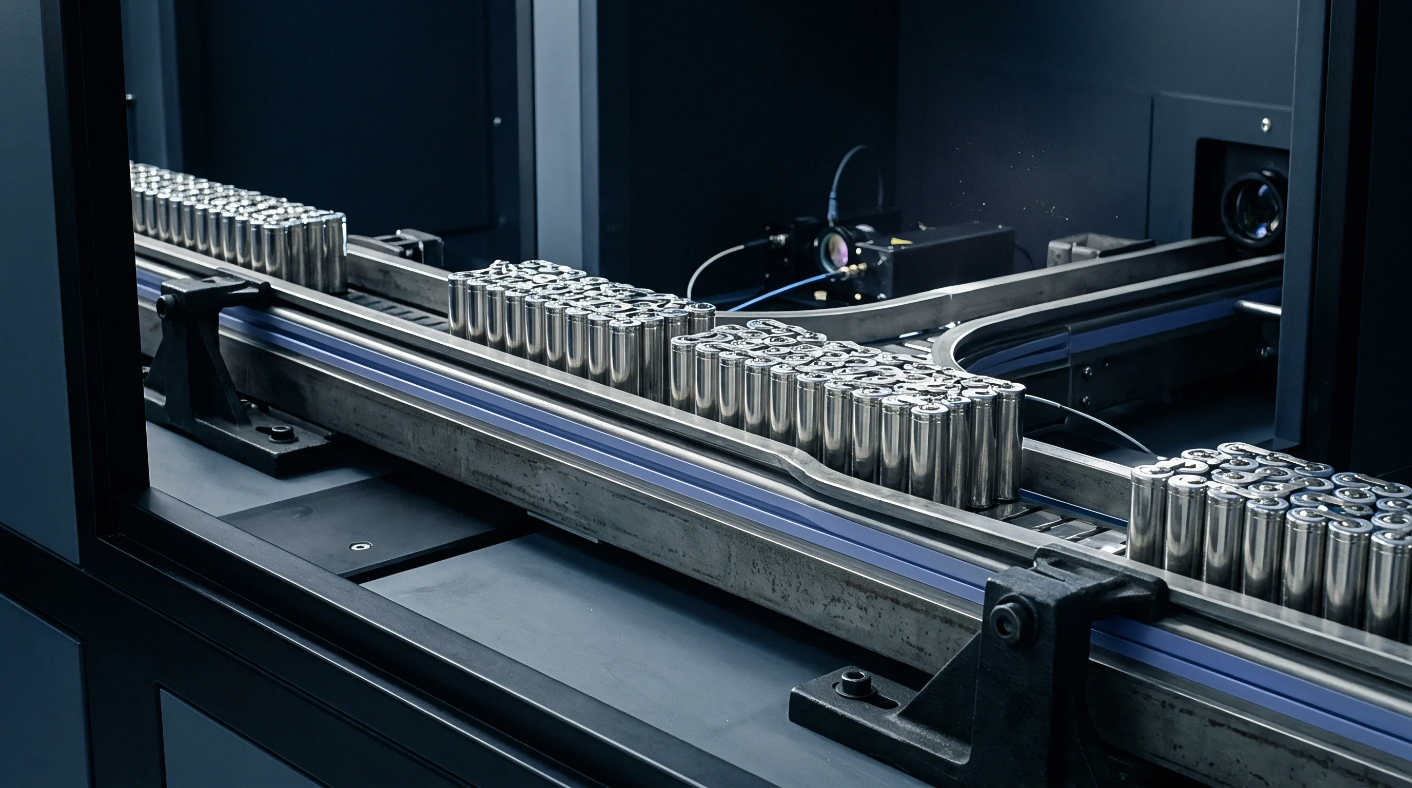
High-speed drawing and ironing of nickel-plated steel for cylindrical battery containers subjects active die inserts to punishing tribological conditions. In transfer presses cycling at four hundred to eight hundred strokes per minute, forcing zero-point-two5 millimeter strip stock through narrow clearance zones generates localized contact temperatures above three hundred degrees Celsius. Standard ingot-cast tool steels such as D2 or M2 suffer from primary carbide segregation, forming coarse chromium or molybdenum carbides that exceed twenty micrometers across.
Under high-frequency impact, these coarse carbide networks concentrate mechanical stress, triggering early micro-chipping along the critical ironing land.
Carbide Microstructure in Atomized Tool Alloys
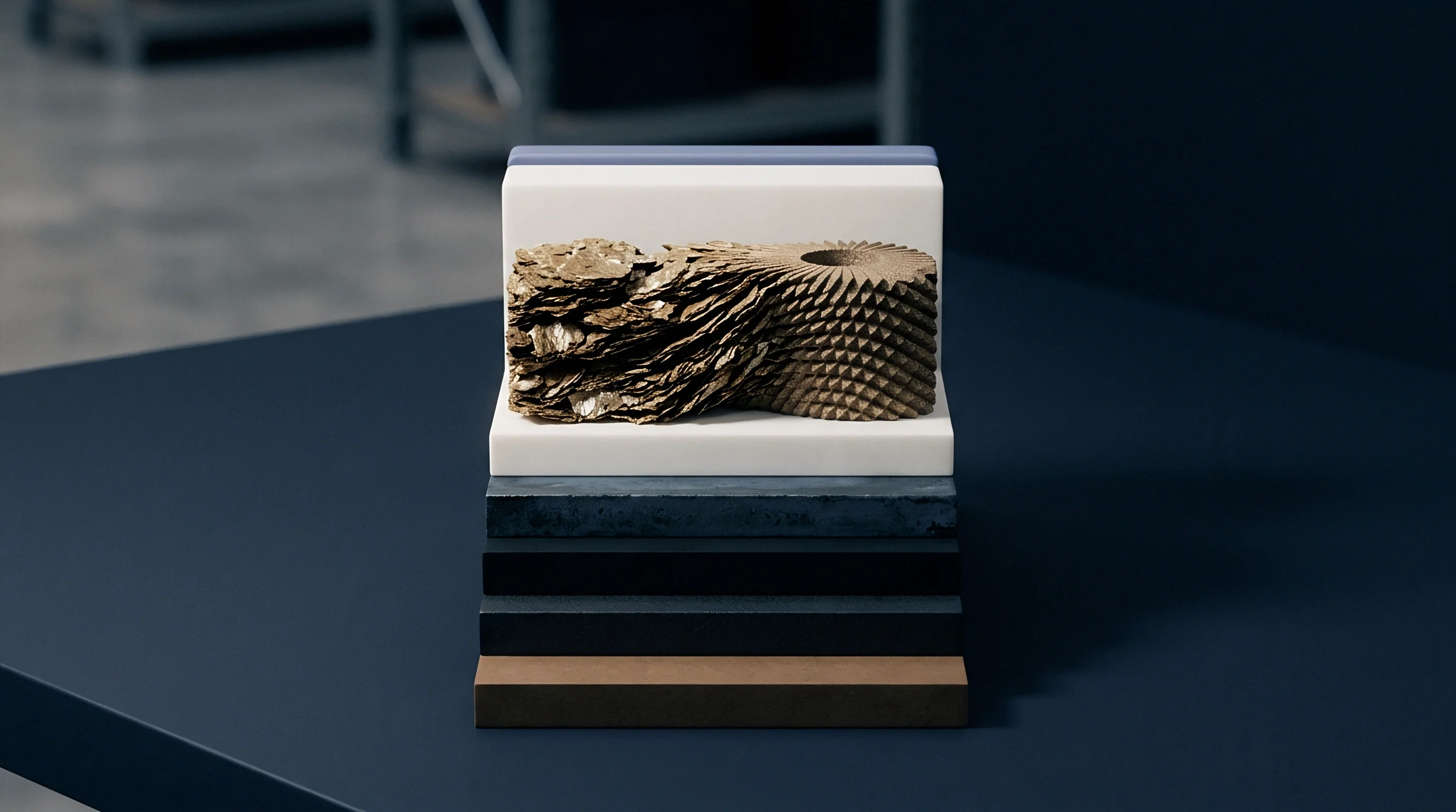
Gas atomization and rapid solidification bypass the heavy elemental segregation inherent to conventional ingot metallurgy. When high-pressure nitrogen jets break a stream of molten tool steel into microscopic droplets cooling at one thousand to ten thousand Kelvin per second, alloying additions freeze in solution rather than pooling. This rapid thermal extraction precipitates an even dispersion of ultra-fine, spherical primary vanadium carbides (MC phase) and tungsten-molybdenum carbides (M6C phase) through the martensitic matrix to resist abrasive micro-plowing, yielding an isotropic carbide distribution across any bar diameter or forging reduction ratio.
Quantitative image analysis of polished metallographic sections confirms this refined carbide distribution. Grade CPM 10V contains roughly seventeen percent vanadium carbide by volume with average carbide diameters under one-point-five micrometers, while Vanadis 8 pairs a similar fine dispersion with greater matrix toughness. In production tooling for 21700 and 4680 cell cans, punches and dies machined from powder metallurgy grades routinely deliver three to five times the working life of ingot-cast equivalents before requiring dimensional re-lapping.
Primary MC vanadium carbide diameter remains below 1.8 micrometers when gas atomization cooling rates exceed 1000 Kelvin per second.

Ironing Pressures and Shell Thickness Tolerances
Wall reductions reaching forty percent per station produce severe localized shear loads across the tool contact interface. To hold cell case outer diameter tolerances during high-volume production, ironing punches and die rings must preserve radial clearances within two micrometers. Conventional cold-work tool steels yield both elastically and plastically under this cyclic loading, particularly where ironing stresses peak at tooling radii, causing dimensional drift that results in wall gauge variation and casing earring defects.
The higher vanadium and chromium levels in powder metallurgy grades push compressive yield strength beyond two thousand four hundred megapascals. This high matrix hardness limits elastic deflection during the stroke, stabilizing the clearance between punch and die ring. When drawing nickel-plated SPCE strip, tool sets can achieve over ten million strokes between sharpenings, provided the heat treatment produces a tempered martensite structure free of retained austenite.

Tenacity
Die components running high-speed container lines need a balance of toughness and yield resistance to survive continuous impact. Punch entrance angles and ironing lands cycle between tensile and compressive stress states on every stroke of the press. If fracture toughness falls short, sharp geometric transitions will suffer sudden cleavage fracture, forcing unplanned downtime for tooling swaps.

Compressive Strength and Mechanical Yield Limits
Ironing loads above two thousand megapascals induce plastic micro-deformation along active die radii. Tool steels for cell case manufacturing therefore require sufficient compressive yield strength to resist mushrooming and maintain critical dimensions. Secondary hardening during high-temperature tempering precipitates sub-microscopic alloy carbides that block dislocation movement through the martensitic matrix under heavy cyclic duty.
Standard heat treatment involves vacuum hardening between ten hundred eighty and eleven hundred eighty degrees Celsius, followed by gas quenching at pressures above six bar. Triple tempering between five hundred twenty and five hundred sixty degrees Celsius transforms retained austenite into martensite, relieving quenching stresses that could otherwise lead to sudden chipping. Inserting a deep cryogenic treatment at minus one hundred ninety-six degrees Celsius between hardening and the initial temper cycle reduces retained austenite volume below one percent.
Retained austenite in heavy draw tooling transforms to brittle martensite under mechanical shock unless drawn down by triple high-temperature tempering.
Impact Resistance and Fracture Toughness Protocols
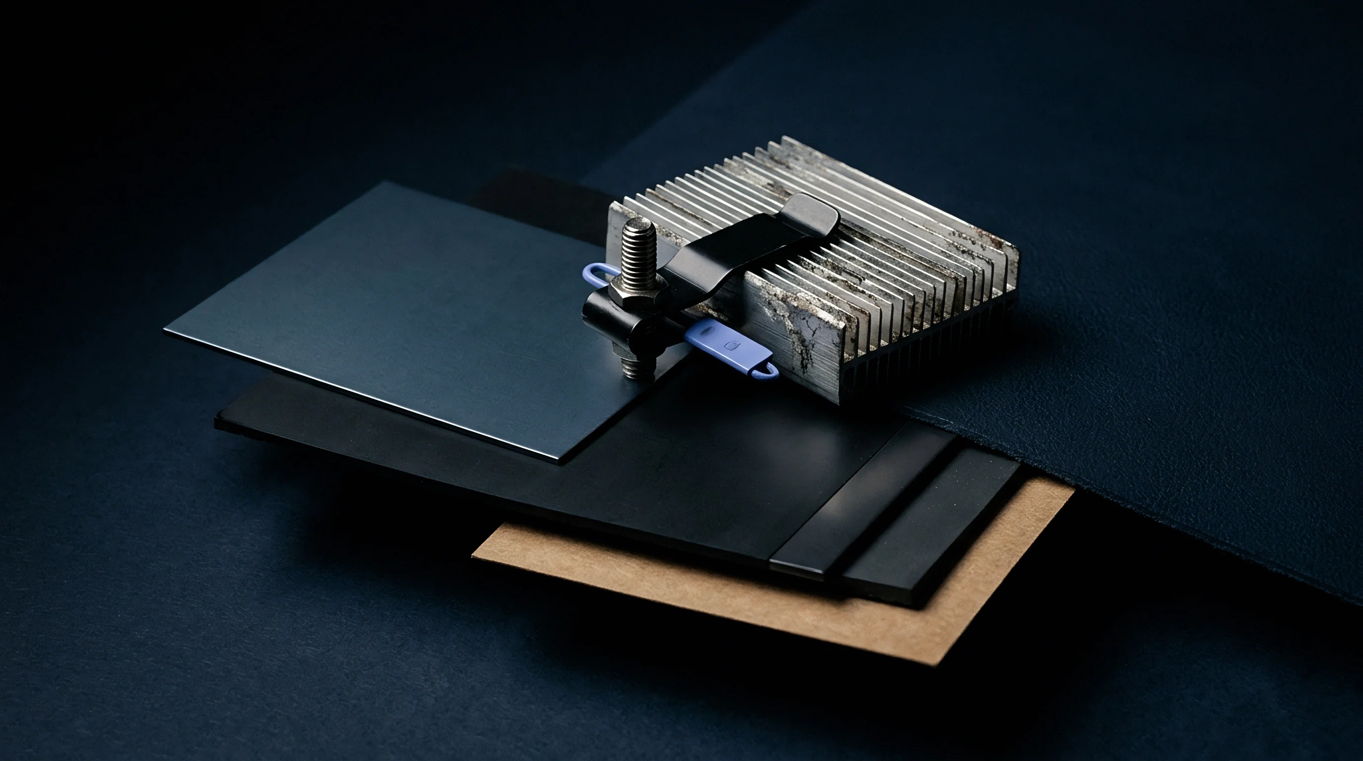
Unnotched Charpy testing measures energy absorption across longitudinal and transverse grain orientations. Because powder metallurgy alloys show minimal directional variance compared to heavily worked ingot steels, their impact toughness is largely isotropic, which prevents preferential cracking along bar centerlines in complex multi-cavity draw dies.
Selecting an alloy for a given die component requires balancing wear resistance against impact toughness. High-vanadium grades like CPM 15V offer maximum abrasion resistance for straight ironing sleeves, though with lower impact absorption. More balanced grades such as Vanadis 4 Extra deliver unnotched Charpy values above fifty Joules while retaining compressive yield strength past two thousand two hundred megapascals, making them well-suited for high-impact punches.
| Grade Designation | Hardness (HRC) | Compressive Yield Strength (MPa) | Unnotched Charpy Impact (J) | Carbide Volume Fraction (%) |
|---|---|---|---|---|
| CPM 10V | 60 – 62 | 2450 | 28 | 17.5 (MC) |
| Vanadis 4 Extra | 58 – 60 | 2250 | 55 | 11.5 (MC) |
| ASP 2053 | 62 – 64 | 2600 | 19 | 21.0 (MC/M6C) |
| CPM M4 (PM) | 62 – 64 | 2500 | 32 | 12.0 (M6C/MC) |
| AISI D2 (Ingot) | 58 – 60 | 1950 | 18 | 14.0 (M7C3 coarse) |


Purity
Non-metallic inclusions in tool steel billets act as initiation sites for high-cycle fatigue cracking. Over tens of millions of cycles in high-speed draw-and-iron tooling, hard ceramic particles like alumina or titanium nitride generate intense local stress concentrations in the surrounding steel matrix, while oxide stringers degrade overall fatigue limits.
Can Gas Atomization Controls Eliminate Non-Metallic Inclusion Clusters?
Inert gas atomization in a vacuum chamber isolates the melt from atmospheric oxygen and refractory erosion. Applying clean melting practices such as electroslag remelting or vacuum induction melting before atomization holds total oxygen in the alloy below twenty parts per million. To control ceramic contamination from nozzle wear, mills use in-line ceramic filtering and strict powder sieving prior to hot isostatic pressing.
Because standard inclusion charts designed for ingot-cast material miss the fine inclusion morphology of atomized alloys, mills turn to automated image analysis to measure particle area fractions, maximum Feret diameters, and cluster spacing. Billet stock earmarked for thin-wall cell case tooling undergoes rigorous micro-cleanliness screening to guard against inclusion-driven subsurface fatigue flaking.
ISO 4967 rating limits exceeding level 0.5 for coarse oxides mandate immediate rejection of tool steel billets intended for multi-stage ironing dies.

Micro-Cleanliness Ratings and Inclusion Limits
Standardized chart methods grade oxide, sulfide, and silicate inclusions by size and distribution. For thin-walled cell cases, stringer-type inclusions must stay under five micrometers in total length; larger inclusions near a polished working face can pull out during stamping, leaving drag lines and scratches along drawn battery shells.
- Chipping at ironing land radius occurs when brittle primary carbides or large oxide stringers fracture under localized shear stresses exceeding the ultimate matrix tensile strength.
- Fatigue flaking from subsurface oxide stringers manifests after millions of press strokes as cyclic contact stresses cause micro-cracks to initiate at hard ceramic particle boundaries and propagate toward the surface.
- Galling onset due to matrix softening develops when localized frictional heating destabilizes the tempered martensite phase, prompting direct adhesive metal transfer between steel strip and die.
- Micro-spalling from retained austenite transformation arises when stress-induced phase transformation alters local volumetric dimensions, creating tensile stress fields that detach surface fragments.
Polish
Working face topography controls material transfer and galling resistance during stamping. Ironing nickel-plated battery cases calls for a mirror finish to minimize frictional shear and stop the strip from locking mechanically into the tool surface. Any subsurface damage left behind by machining will accelerate wear and undermine coating adhesion.
Recast Layer Mitigation Following Electrical Discharge Machining
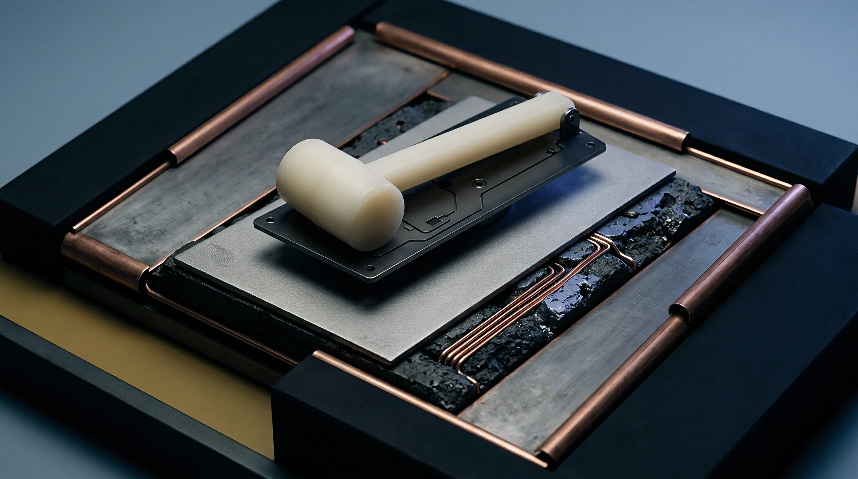
Wire EDM leaves an un-tempered, brittle white layer laced with micro-cracks. This recast zone of re-melted steel and copper or brass wire residue carries high residual tensile stresses and erratic microhardness, which will trigger premature flaking and spalling if left on the tool.
Clearing the recast layer requires a sequence of stress relief and diamond lapping. Toolmakers grind or chemically polish away at least fifteen to twenty micrometers beyond the visible thermal damage boundary. A secondary temper set twenty degrees Celsius below the final tempering temperature relieves machining stresses before the tool moves to surface coating.
- Wire EDM skin removal by fine grinding removes the re-melted alloy zone using specialized diamond-vitrified grinding pins under heavy oil coolant flush.
- Sub-critical stress relief tempering lowers residual tensile stresses created by abrasive machining forces without sacrificing core substrate hardness or dimensional tolerances.
- Isotropic superfinishing to surface finish target utilizes diamond lapping compounds down to one-quarter micrometer particle size to eliminate directional grind lines on active ironing radii.
- Duplex PVD coating deposition applies a thin chromium nitride primer layer followed by high-hardness aluminum titanium nitride to provide an adhesive wear barrier against nickel transfer.

Superfinishing and Duplex Coating Adhesion
Lapping surfaces down to fifty nanometers Ra or better provides smooth lands that lower friction prior to ceramic film deposition. Physical vapor deposition coatings such as AlCrN or TiAlN act as hard thermal barriers against adhesive galling from nickel-plated strip. How well these coatings adhere depends on substrate cleanliness, grain boundary integrity, and core microhardness.
Coating adhesion is verified with Rockwell C indent testing per VDI 3198, where acceptable quality requires clean indent perimeters without radial delamination or continuous spalling (Classes HF1 and HF2). Scratch testing confirms failure thresholds (L3), with acceptable coatings withstanding continuous stylus loads beyond forty-five Newtons before detaching from the substrate.

Tribology
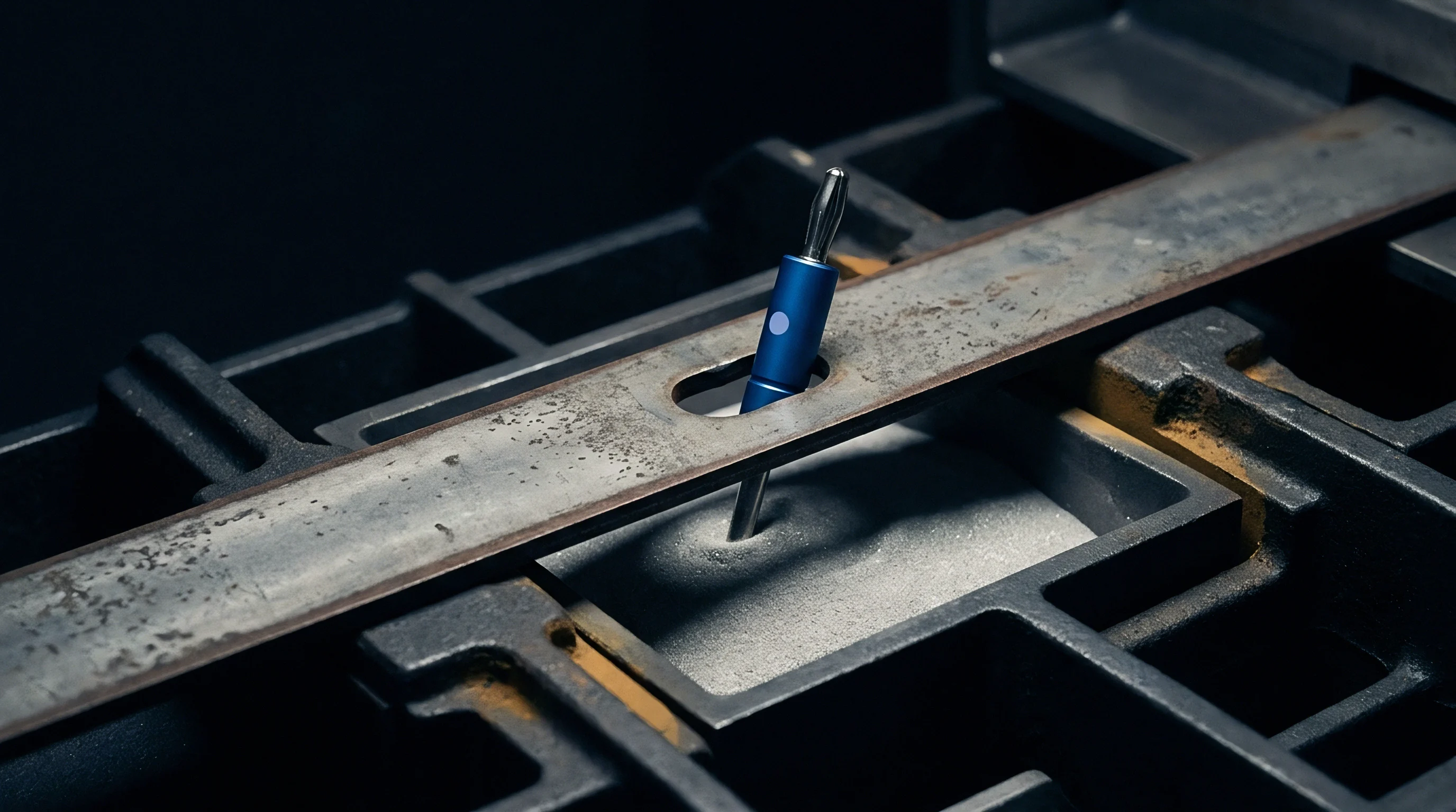
Abrasive wear data correlates directly with die life in high-speed battery can stamping. Active tool steel faces must handle two distinct regimes: fine abrasive wear from oxide particles on incoming steel strip, and intense adhesive wear during high-pressure ironing passes that quickly score unprotected dies.
Laboratory Wear Characterization and Field Correlation
Standardized dry sand rubber wheel testing ranks candidate alloys by volume loss under quartz abrasive flow. High-vanadium powder metallurgy steels consistently outperform high-chromium ingot grades under identical conditions, as vanadium carbides reach approximately twenty-eight hundred HV and resist scoring by quartz or iron oxide fines.
Pin-on-disk trials evaluate sliding friction and metal transfer against nickel-plated strip under flooded synthetic emulsion lubrication, closely matching the environment inside a transfer press. PM grades rich in primary carbides maintain low friction coefficients below zero-point-one-five, which suppresses the frictional heating, galling, and micro-welding that distort shell wall gauge at high operating speeds.
| Tool Steel Grade | Coating Architecture | ASTM G65 Volume Loss (mm³) | CoFF vs Ni-Plate (Flooded) | Strokes to Refurbishment |
|---|---|---|---|---|
| CPM 10V | Uncoated (Polished) | 18.2 | 0.18 | 2,500,000 |
| CPM 10V | Duplex AlCrN (PVD) | 2.1 | 0.08 | 12,000,000 |
| Vanadis 4 Extra | Duplex AlCrN (PVD) | 4.5 | 0.09 | 8,500,000 |
| ASP 2053 | Duplex DLC (PVD) | 1.2 | 0.05 | 15,000,000 |
| AISI D2 (Ingot) | Single TiN (PVD) | 42.0 | 0.22 | 1,200,000 |
Galling Resistance in Nickel-Plated Steel Drawing
Intermetallic transfer between strip stock and die tooling produces linear scoring along drawn shell walls. This cold welding begins when local contact pressure breaks through surface oxide films, putting bare tool steel in direct contact with the nickel layer. Once nickel builds up on the die, it scores incoming cases and forces line stops for manual polishing.
- Substrate hardness verification confirms core strength exceeds sixty HRC to prevent substrate deformation beneath thin ceramic surface coatings.
- Microstructure grain size rating ensures primary austenite grain size remains finer than ASTM 10 to protect edge toughness on punch lands.
- Subsurface residual stress profile measures compressive stress depth via X-ray diffraction to confirm adequate grinding damage mitigation.
- Duplex coating layer thickness verification measures ceramic coating thickness via calo-testing to ensure uniformity between two and four micrometers across draw radii.
While pin-on-disk testing provides a baseline for comparing alloys, press shop conditions introduce complications that bench tests rarely capture. Emulsion concentration shifts, thermal growth on long punches running at six-hundred-stroke-per-minute speeds, and coil-to-coil thickness variation all alter tool wear in practice, while reproducing the transient contact pressure spikes of press shock remains difficult in the laboratory.

Audit
Procuring powder metallurgy tool steels requires thorough verification of mill certificates before machining begins. Counterfeit bar stock or sub-standard powder compacts containing internal microporosity risk catastrophic breakage inside high-speed transfer presses. Standard verification procedures establish strict acceptance criteria for chemistry, volumetric integrity, and microstructural uniformity.
Ultrasonic Soundness and Macro-Defect Verification
Immersion ultrasonic inspection identifies internal voids and porosity beneath the surface. Hot isostatic pressing consolidates atomized powder under high argon pressure and elevated temperature, but incomplete densification leaves micro-voids that can collapse under the cyclic contact stresses of stamping.
Procurement specifications for die blanks mandate Quality Class 4 compliance per SEP 1921 or EN 10228 standards. Pulse-echo inspection at five to ten Megahertz resolves internal flaws down to zero-point-five millimeters equivalent flat-bottom hole diameter, and billets showing attenuation losses or back-wall echo drops over three decibels are rejected and quarantined.
Quality Class 4 ultrasonic certification per SEP 1921 mandates zero internal void detections above 0.5 millimeter equivalent flaw size in forged PM blocks.

Metallurgical Dossier Integrity and Traceability
Mill inspection certificates link furnace heat lot codes directly to test cuts from forged bar stock. Complete dossiers contain optical emission spectrometry chemistry reports, heat treatment furnace charts, and ultrasonic scan records to substantiate material quality.
Chemical analysis confirms that alloying additions match specified powder metallurgy grades, keeping vanadium, molybdenum, and carbon within tight ranges to yield expected carbide fractions after hardening. Archimedes density testing verifies that compaction exceeds ninety-nine-point-nine percent of theoretical density, ensuring solid material throughout large cross-sections before committing blanks to precision machining.