Solid State Battery Interface Pressure Retention Mechanics under High Dynamic Cycling Protocols
Dynamic cycling of solid-state cells demands active dynamic pressure retention fixtures to prevent interfacial voiding and early capacity loss.


Stack
Solid-state cells with metallic lithium or silicon anodes undergo periodic volume changes during electrochemical insertion and extraction. Unlike liquid-electrolyte lithium-ion systems where solvent fills porous voids regardless of expansion, solid-state designs depend entirely on direct physical contact across solid-solid interfaces. Moving lithium ions across sulfide, oxide, or polymer solid electrolytes requires continuous contact at the separator boundary.
During charging, lithium deposits at the anode interface, causing local expansion. During discharge, stripping leaves behind micro-voids if external compression is insufficient.
Interfacial resistance rises exponentially when compression falls below specific threshold limits. Sulfide solid electrolytes such as lithium phosphorus sulfur chloride (Li6PS5Cl) show microstructural ductility under pressure. They plasticize and creep into surface asperities under uniaxial compressive loads between 2.0 MPa and 5.0 MPa.
Oxide electrolytes like lithium lanthanum zirconium oxide (LLZO) possess high shear moduli exceeding 60 GPa, preventing room-temperature plastic flow. Oxide interfaces require high local pressure to maintain contact with soft lithium metal. Without active pressure retention, dynamic volume shifts generate localized delamination, current constriction, and high-density plating.
Unchecked void formation and local high-density plating eventually drive dendritic growth that shorts the cell.
Dynamic cycling profiles in electric vehicle traction drives and industrial energy storage accelerate interfacial degradation. High current pulses generate rapid lithium stripping at the anode contact layer. When the stripping rate exceeds the self-diffusion and bulk creep rates of metallic lithium, vacancy concentration spikes at the interface.
Applied external pressure forces bulk metallic lithium to flow plastically into these void sites, preserving contact continuity. Lower stack pressures allow voids to accumulate, decreasing active contact area and elevating local current density at surviving contact points.

Electrolyte Interfacial Physics and Volumetric Mechanics
Chemical reactions at the junction between solid electrolytes and active electrode materials depend heavily on continuous particle contact. Solid-state architectures present distinct stress responses based on electrolyte crystal structure and anode chemistry. Sulfide-based systems exhibit dynamic breathing during charge and discharge, producing stack thickness variations up to 15 percent in lithium-metal pouch cell configurations.
Uniaxial compressive fixtures must compensate for continuous volume fluctuations without letting pressure drop below critical interfacial thresholds. When stack pressure falls below 1.5 MPa in sulfide systems, interface contact area drops below 80 percent of nominal geometric area within 100 deep charge-discharge cycles. Oxide-based systems show lower macroscopic volume shifts but experience severe stress concentration at rigid ceramic contact points, promoting micro-cracking across brittle separator membranes.
| Electrolyte Chemistry | Nominal Anode Composition | Operating Pressure Range (MPa) | Dynamic Thickness Strain (%) | Critical Pressure Threshold (MPa) |
|---|---|---|---|---|
| Argyrodite Sulfide (Li6PS5Cl) | Lithium Metal (Pure) | 2.5 – 6.0 | 12.0 – 18.0 | 1.8 |
| Garnet Oxide (LLZO) | Lithium-Silicon Composite | 5.0 – 15.0 | 4.0 – 8.0 | 3.5 |
| PEO-LiTFSI Polymer Blend | Lithium Metal (Pure) | 0.3 – 1.2 | 8.0 – 14.0 | 0.2 |
| Halide (Li3YCl6 Hybrid) | Silicon Anode (90 wt%) | 3.0 – 8.0 | 20.0 – 28.0 | 2.2 |
Sulfide solid electrolyte stacks operated at 5.0 MPa pressure under 3C charge profiles lose 14 percent active contact area after 400 cycles when dynamic compression is unmanaged.
Stripping and plating rates during fast cycling frequently exceed the plastic creep rate of metallic lithium.
Dynamic current loads aggravate interfacial degradation by altering thermal and mechanical stress simultaneously. Elevated charge rates generate localized heat through ohmic resistance across the solid interface, softening metallic lithium while altering spring pre-load forces within external retaining frames. Lower operating temperatures increase lithium yield strength, raising the minimum uniaxial pressure necessary to induce plastic creep into vacancy voids created during discharge.


Clamp
Maintaining uniform compressive loads across active cell surfaces throughout operational lifetimes demands customized mechanical constraint systems. Battery modules incorporate dynamic pressure retention fixtures designed to absorb stack expansion while preserving minimum pre-load limits. Belleville disc spring stacks, wave springs, micro-cellular elastomeric foam pads, and active hydraulic micro-actuators represent primary structural retention mechanisms.
Spring compliance directly governs the operational fatigue life of the clamping assembly.
Mechanical spring systems experience cyclic stress relaxation under continuous thermal cycling and dynamic compression. Disc spring stacks engineered for solid-state cell enclosures lose load over prolonged thermal exposure. When elastomeric foam dampers are used, compressive creep permanently reduces spring force, shifting the mechanical equilibrium point of the module enclosure assembly.

Mechanical Retainer Sizing Procedure
Engineers calculating pre-load forces for solid-state module enclosures follow a structured analytical sequence to select Belleville disc spring configurations.
- Measure active cell surface area and determine target operational pressure range based on solid electrolyte dynamic creep parameters.
- Calculate maximum macroscopic thickness expansion of the cell stack at maximum state of charge, accounting for thermal expansion coefficients of aluminum current collectors and end plates.
- Determine minimum allowable stack pressure at fully discharged state to prevent interfacial void growth during high-rate discharge.
- Select Belleville spring disc thickness, outer diameter, and series-parallel stacking arrangement to deliver a spring rate matching cell stack expansion compliance.
Rigid end-plate flexure represents a secondary source of uneven pressure distribution across solid-state cell surfaces. Aluminum or steel end plates under heavy pre-load flex outward at plate centers, creating pressure gradients where peripheral stack regions experience up to 40 percent higher compressive stress than central stack regions. Structural ribbing, high-modulus carbon composite end plates, or curved load-distribution inserts eliminate uneven interfacial pressure distributions.
Mechanical spring assemblies designed without structural thermal isolation transfer cell heating directly into compression elements, accelerating force relaxation.
Failure to compensate for thermal expansion and mechanical relaxation during fixture design leads to severe stack degradation. Over-constrained cell stacks develop internal pressure spikes exceeding 20 MPa at high state of charge, causing mechanical fracture of fragile ceramic electrolyte membranes and immediate short-circuit failures.


Yield
High rate electrical discharge and dynamic acceleration pulses induce severe mechanical stress transients within active battery layers. Dynamic driving cycles present unpredictable load amplitudes where rapid current spikes alternate with regenerative braking charge pulses. Interfacial pressure retention mechanics must account for rapid phase shifts and high strain rates at electrode boundaries.
When mechanical contact degrades across the interface, interfacial impedance climbs rapidly.
Dynamic compression hysteresis occurs when mechanical spring recovery speeds lag behind rapid electrochemical cell contraction during fast discharge. If cell thickness decreases faster than the mechanical retainer expands, transient pressure drops develop across active interfaces. During these millisecond-scale low-pressure windows, high current densities trigger rapid void growth and localized interfacial detachment.
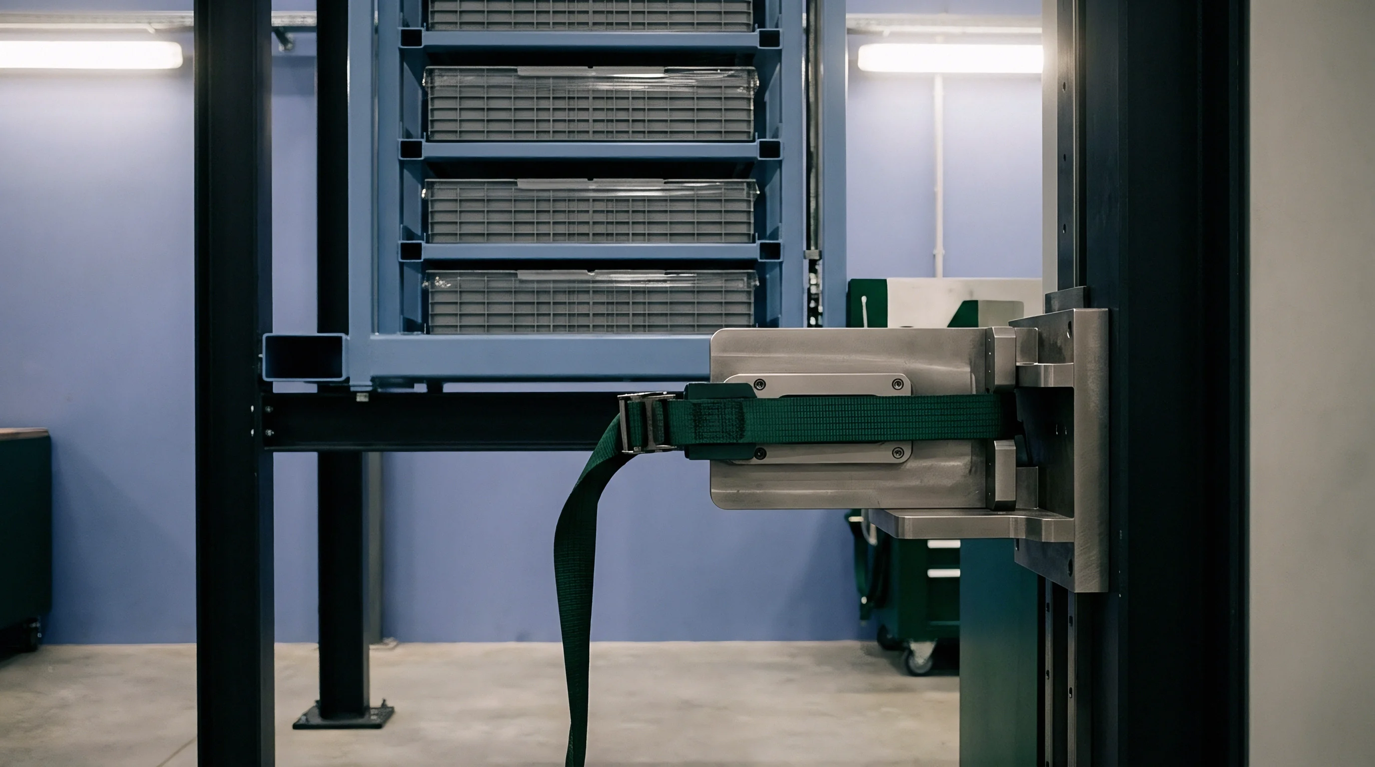
Fast Stripping Void Nucleation Mechanics
Current densities exceeding 2.5 milliamperes per square centimeter extract lithium ions from the anode faster than self-diffusion can replenish the interface. Local vacancy concentration rises, nucleating interfacial micro-voids. External stack pressure must drive bulk plastic yield of lithium metal to fill these vacancies continuously.
Interfacial flux stability requires external mechanical stress to exceed the temperature-dependent plastic yield strength of metallic lithium. At 25 °C, lithium yield strength ranges from 0.8 MPa to 1.5 MPa depending on grain size and purity. At lower ambient operating temperatures such as -10 °C, lithium yield strength rises above 3.0 MPa, demanding significantly higher dynamic stack pressure to maintain contact during aggressive discharge protocols.

Worked Calculation of Spring Relaxation under Fast Charging
Consider a 50 ampere-hour pouch cell operating with a sulfide electrolyte and a pure lithium metal anode. The active area measures 200 cm² (0.02 m²). Target initial compressive pressure equals 5.0 MPa, requiring an absolute force of 100,000 Newtons applied across the stack face.
Solid-state cell thickness increases by 250 micrometers (0.25 mm) at full charge.
Assume a Belleville spring stack retainer with a nominal stiffness k = 80,000 N/mm. During complete charging, stack expansion compresses the spring assembly by an additional 0.25 mm, increasing applied force by 20,000 Newtons. Peak stack pressure at full state of charge reaches 6.0 MPa, calculated as 120,000 Newtons over 0.02 m² surface area.
Over 800 thermal and dynamic cycling loops, structural stress relaxation reduces nominal spring pre-load force by 8 percent. Accumulated foam pad creep accounts for an additional 0.10 mm permanent compression set. The net pre-load force at fully discharged state falls from 100,000 Newtons to 84,000 Newtons, yielding a discharged stack pressure of 4.2 MPa.
Under cold operating conditions where lithium yield strength increases, this reduced pressure fails to suppress void growth, initiating capacity fade.
| Discharge C-Rate | Local Stripping Density (mA/cm²) | Minimum Required Stack Pressure (MPa) | Void Growth Probability (%) | Hysteresis Delay Time (ms) |
|---|---|---|---|---|
| 0.5C Continuous | 0.8 | 1.5 | < 1.0 | 12 |
| 1.0C Continuous | 1.6 | 2.8 | 3.5 | 25 |
| 3.0C Pulse (10s) | 4.8 | 5.5 | 18.0 | 85 |
| 5.0C Pulse (5s) | 8.0 | 8.2 | 42.0 | 140 |
Dynamic pulse charging strips lithium from interface boundaries faster than bulk creep fills interfacial vacancies.
Silicon anodes swell substantially during lithium insertion, compounding dynamic stress.
Whether mechanical pre-load fixtures can dynamically adjust strain rates in real-time without introducing parasitic actuator energy consumption remains an open electro-mechanical design problem for cell integrators.


Bench
Laboratory qualification requires continuous monitoring of stack compressive loads during combined electrical cycling and environmental shaking. Standard battery testing protocols evaluate electrical performance under static thermal conditions. Solid-state cell evaluation requires synchronized dynamic mechanical loading, environmental thermal chambers, multi-axis vibration shakers, and dynamic electrochemical impedance spectroscopy.
Dynamic mechanical verification protocol setups use thin-film piezoresistive sensor arrays embedded directly within cell stacks. These sensors map real-time pressure distribution profiles during aggressive dynamic stress testing. Sensor calibration must account for thermal drift within environmental chambers operating between -40 °C and 85 °C.

Will Compression Assemblies Pass UN 38.3 Testing?
Federal transport regulations test battery pack integrity under sinusoidal sweeps ranging from 7 hertz to 200 hertz. External mechanical compression frames alter the structural resonance frequency of solid-state cell modules. Belleville disc springs and elastomeric damper elements can vibrate violently at natural resonance frequencies, causing transient pressure spikes or temporary loss of stack compression during vibration testing.
Mechanical vibration profiles specified in UN 38.3 Test T.3 induce relative microscopic motion between internal cell layers if pre-load fixtures lose compression during peak sinusoidal acceleration. Instantaneous interfacial contact separation causes internal micro-arcing across solid electrolyte layers, generating local thermal hotspots and dielectric separator breakdown.

Interfacial Degradation Failure Modes
Dynamic load retention systems experience several distinct degradation mechanisms when subjected to coupled mechanical stress and fast charge protocols.
- Micro-void Delamination Interfacial contact loss occurs when localized stripping rates exceed lithium metal creep velocity, causing exponential growth of internal impedance.
- Grain Boundary Penetration Lithium dendrites grow through solid electrolyte grain boundaries when localized pressure gradients produce non-uniform stress distribution across cell surfaces.
- Spring Stress Relaxation Continuous thermal exposure reduces spring pre-load forces over extended operating lifetimes, dropping stack pressure below critical retention thresholds.
- End-Plate Deflection Structural bending of constraint plates causes non-uniform pressure distributions, accelerating active material fatigue near central cell areas.
UN 38.3 Section 38.3.4.3 specifies continuous voltage monitoring during sinusoidal vibration profiles, treating any transient voltage drop below 2.8 volts as an immediate test failure.
Microstructural defects grow progressively under sustained cyclic loading.
Contractual supply agreements specifying cell lifecycle parameters under IEC 62660-1 standards mandate that stack retention fixtures retain at least 85 percent of initial pre-load force after completing 1,000 continuous dynamic charge-discharge cycles.


Carriage
Shipping solid-state cells contained within pre-stressed mechanical fixtures introduces dual regulatory oversight during international transit. Pre-compressed modules contain high mechanical potential energy stored within heavy spring assemblies in addition to stored electrochemical energy. Dangerous goods regulations treat pre-stressed lithium cell packs under specialized packaging classifications.
Air freight forwarders reject uncertified compressed battery packs.
UN Packaging Instruction 965 Section IA governs commercial international air shipments of lithium ion batteries. Solid-state modules equipped with integrated compression springs must demonstrate structural containment integrity under UN 38.3 T.4 shock protocols, which apply 150g peak acceleration pulses across six directional axes. Retention fixtures must sustain structural integrity without releasing stored spring tension or altering internal stack compression.

Transport Safety and Dossier Requirements
Compliance documentation for high-energy battery shipments obligates the shipper to trace every physical cell lot to certified laboratory test results. Hazardous material transport declarations require accurate weight calculations incorporating heavy mechanical compression hardware into total gross mass declarations.
| Regulatory Body | Standard / Instruction | Mechanical Scope | Mandatory Documentation |
|---|---|---|---|
| United Nations (UN) | UN 38.3 Test T.4 (Shock) | 150g acceleration pulse sustainability without compression force loss | UN 38.3 Test Summary Report (ITS) |
| ICAO / IATA | PI 965 Section IA | State of Charge capped at 30% for commercial air transport | Dangerous Goods Shipper Declaration |
| European Union | EU Battery Regulation 2023/1542 | Carbon footprint including structural retention hardware mass | EU Battery Passport and CE Dossier |
| US DOT / PHMSA | 49 CFR 173.185 | Containment of mechanical energy in pre-stressed springs | Class 9 Hazmat Transit Permit |
Complete safety documentation requires specific compliance records before international carriers accept shipments of pre-stressed battery modules.
- UN 38.3 Test Summary Documentation proving completion of mandatory T.1 through T.8 environmental, mechanical, and electrical safety tests under pre-stressed fixture conditions.
- Packaging Instruction 965 Certificate Shippers declaration validating state-of-charge limits below 30 percent and approved protective packaging outer containers.
- Pre-Load Pressure Calibration Sheet Factory inspection reports verifying initial dynamic spring pre-load settings and structural end-plate mechanical torque values.
- EU Battery Passport Compliance File Operational carbon footprint records accounting for raw steel, spring alloys, and active solid-state material processing emissions.
Without active dynamic clamping, solid-state cells degrade within fifty cycles.
Dynamic pressure retention fixtures often fall outside cell warranty coverage, leaving pack integrators responsible for any interfacial degradation caused by external housing flexure during transport or operation.

Ledger
Commercial contracts for solid-state cell delivery explicitly divide mechanical constraint responsibilities between cell manufacturers and battery pack integrators. Cell datasheets specify narrow operating pressure windows necessary to achieve stated cycle life figures. If an integrator designs a module enclosure that fails to maintain required uniaxial pressure across all operating temperatures, suppliers deny warranty liability for premature capacity loss.
Integrating dynamic compression fixtures increases pack-level manufacturing expenses and reduces volumetric energy density. Belleville spring stacks, structural tie-rods, and heavy end-plates add non-active dead weight to battery systems. For a 100 kWh electric vehicle pack, mechanical retention hardware can add 35 to 60 kilograms of structural steel or high-strength aluminum alloys, reducing gravimetric energy density by 12 to 18 percent.
Primary warranty and compliance obligations ultimately remain with the importer.
Procurement contracts must incorporate clear qualification protocols covering mechanical pre-load retention over operational lifetimes. A worked financial exposure model illustrates the commercial risk of unmanaged pressure loss in a grid-scale 10 MWh storage installation using solid-state sulfide cells. Assuming a cell procurement cost of $110 per kilowatt-hour, initial cell capital expenditure totals $1,100,000.
If module retention fixtures experience 12 percent spring force relaxation over three years of operation, interfacial contact loss accelerates degradation. Average cell capacity retention drops below the 80 percent warranty threshold at cycle 1,400 instead of the contracted 3,500 cycles. Unscheduled module replacement costs, labor, logistics, and downtime penalties add $450,000 in unbudgeted operational expenditure.
Severe mechanical separator breakdown leading to thermal runaway releases toxic off-gasses.
Contractual penalty clauses allocating field failure costs depend on unambiguous bench testing data establishing whether capacity decay resulted from internal cell material degradation or external pressure retention failure. Integrating calibrated strain gauges into sample module assemblies provides verifiable pressure history records, protecting procurement teams against unwarranted claim rejections.
Fixtures designed to survive dynamic cycling protocols maintain stack compression stability across thermal extremes, preserving cell longevity while containing regulatory compliance exposure.