Dynamic Pressure Regulation for Close Coupled Atomization Nozzle Systems
Dynamic regulation of gas supply pressure preserves aspiration differential at close-coupled nozzles, eliminating melt freeze-off and controlling powder size.


Plume
Gas jet kinetics at the exit annulus govern primary liquid disintegration in close-coupled atomizers. Liquid metal, precursor solutions, or active slurries flow through a central delivery tube surrounded by a high-velocity annular gas stream. Converging gas and liquid directly at the nozzle tip eliminates the free-fall zone seen in open nozzles, transferring kinetic energy directly into the liquid stream upon discharge.
Energy transfer efficiency depends on maintaining a precise pressure balance at the melt exit interface. Gas velocity exiting supersonic or convergent-divergent annular channels creates a local static pressure drop directly beneath the liquid tip orifice. This depressurization ~ designated as suction pressure or aspiration differential ~ draws liquid forward through the feed tube.
Fluctuations in gas supply pressure alter this differential instantly. Because gas density governs aspiration depth, an unexpected drop in supply pressure reduces suction force, lowering mass flow or pulling liquid back into the gas manifold.

Coupled Gas Dynamics and Liquid Delivery Mechanics
Supersonic expansion through convergent-divergent annular channels sets up the local static force field surrounding the liquid delivery tip. Exiting gas expands from supply pressure down to ambient chamber pressure, accelerating past sonic velocity once the pressure ratio crosses critical thresholds. As the gas expands, shear stress at the gas-liquid boundary induces primary breakup, stripping thin liquid sheets from the liquid core into fine filaments and droplets.
Droplet size distribution scales with the gas-to-melt mass ratio and gas exit velocity. Weber number regimes dictate whether liquid sheets break up via wave instability, membrane stripping, or catastrophic jet breakup. When gas pressure fluctuates dynamically, shear forces change across microsecond timeframes, creating non-uniform initial droplet diameters.
Stabilizing gas pressure at the annulus keeps the Weber number within target bounds, protecting powder sphericity and minimizing satellite formation on cooling powder particles.
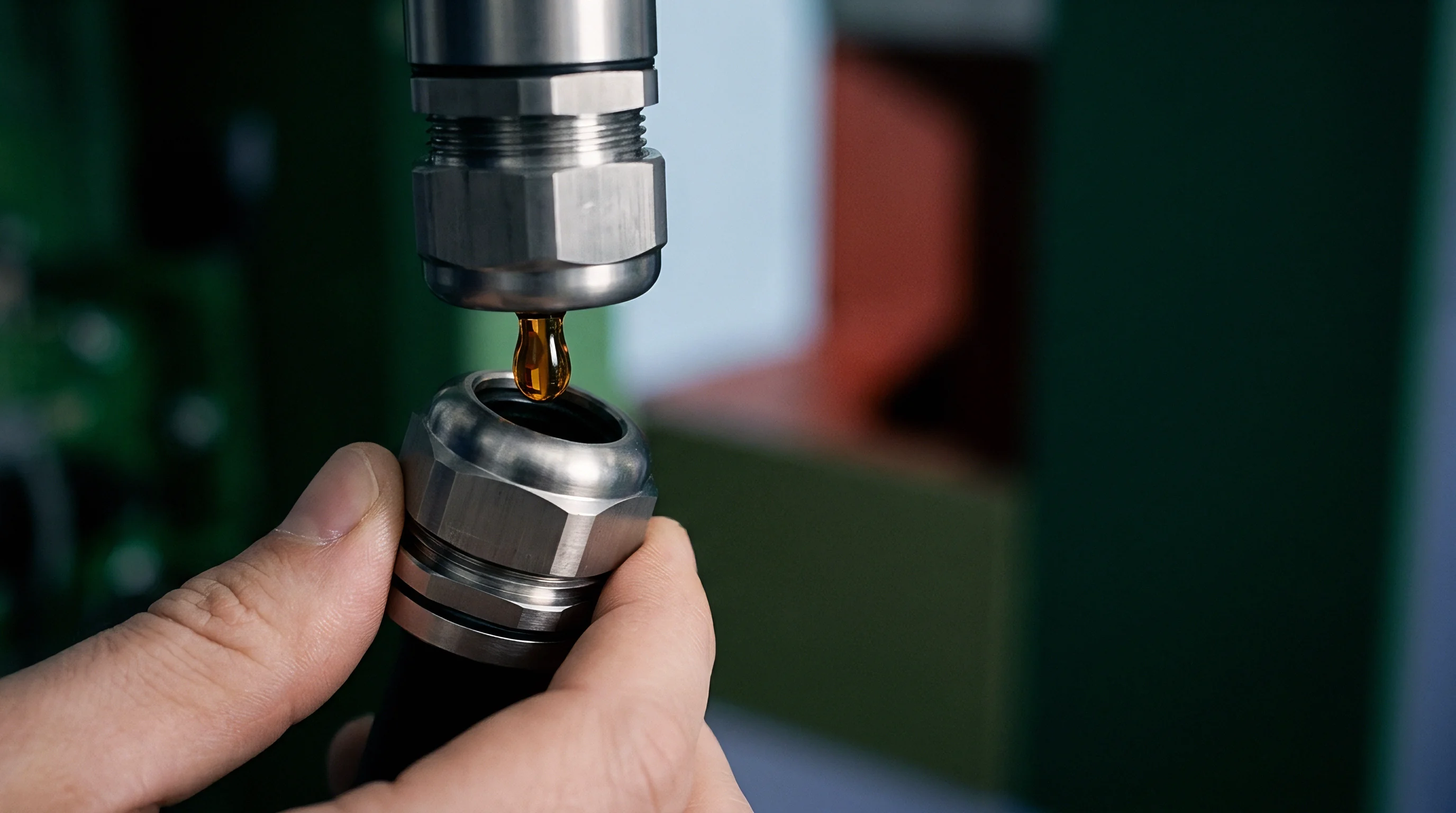
Aspiration Differential and Melt Tip Recirculation
High-velocity gas shearing drops static pressure below ambient levels at the orifice exit. The net driving force on the liquid stems from the pressure difference between the supply reservoir and the tip exit face. Operational stability requires keeping this differential consistently negative, typically between 5 and 25 kilopascals below ambient chamber pressure.
Positive static pressure at the tip leads to catastrophic flow reversal, forcing molten liquid or slurry into the annular gas pathways.
Maintaining constant gas-to-melt mass ratio stabilizes particle size distribution during sudden melt head changes.
Recirculation zones beneath the liquid tip face exacerbate flow instability if pressure regulation lags. Recirculating gas vortices pull fine droplets back toward the hot nozzle structure, where cold expanding gas lowers local temperatures. When recirculating metal droplets hit cold nozzle surfaces, liquid freeze-off occurs, forming accretions or lip buildup.
Incremental lip buildup distorts annular gas geometry, shifting jet symmetry and causing severe process drift. Operating above the critical pressure margin maintains stable liquid extraction and suppresses nozzle lip accretion without relying on active gas throttling.


Pneumatics
Gas delivery manifold architecture controls the speed and fidelity of mass flow adjustments during production. Standard industrial gas lines exhibit internal friction, volumetric capacitance, and dynamic flow resistance that dampen pressure regulation signals sent from control systems. Designing a pneumatic regulation setup for close-coupled atomization demands careful placement of high-speed control valves, accumulation volumes, and dynamic suppression components relative to the physical nozzle inlet.
Volumetric capacitance inside gas piping acts as a low-pass mechanical filter. Long pipe runs between gas regulators and the nozzle manifold delay pressure change delivery, introducing phase lag into active control loops. Minimizing line volume between the primary regulator valve and the annular gas chamber increases control bandwidth.
High-frequency regulation requires short, rigid piping runs paired with direct-acting proportional actuators mounted close to the atomization head.

Proportional Valve Topology and Supply Reservoir Sizing
Direct-operated piezoelectric control elements yield switching frequencies exceeding two hundred Hertz while minimizing mechanical backlash. Traditional motor-driven spool valves fail to keep pace with dynamic pressure ripples in high-pressure gas lines, exhibiting mechanical hysteresis and slow step response times. Piezo-actuated variable orifice valves respond within three milliseconds to step changes in control signal voltage, providing precise control of gas mass flow into the atomization chamber.
Upstream gas accumulation tanks buffer high-volume pressure drops during transient adjustments. Tank sizing relies on maximum mass discharge rates and allowable supply pressure decay during dynamic shifts. Internal gas line dampeners prevent downstream shock waves from feeding back into the valve diaphragm.
Stable inlet gas supply conditions ensure that valve adjustments translate linearly into gas exit velocity shifts at the close-coupled tip.
Selecting valve and reservoir hardware requires matching dynamic response constraints with line flow capacity across expected operating ranges.
| Topology Type | Response Time | Hysteresis Margin | Mass Flow Capacity | Bandwidth Limit |
|---|---|---|---|---|
| Direct-Drive Piezo Servo Valve | 1.5 to 3.0 ms | < 0.5% full scale | 10 to 40 Nm³/min | 250 Hz |
| High-Speed Solenoid Array | 5.0 to 12.0 ms | < 1.2% full scale | 30 to 100 Nm³/min | 80 Hz |
| Motorized Precision Dome Regulator | 45.0 to 120.0 ms | < 2.5% full scale | 100 to 500 Nm³/min | 10 Hz |
| Pneumatic Pilot-Operated Valve | 15.0 to 35.0 ms | < 1.8% full scale | 50 to 250 Nm³/min | 35 Hz |

High-Frequency Dynamic Gas Pressure Modulation
Pulsing delivery gas modifies shear stress across the atomization zone without altering total gas mass consumption. Controlled pressure oscillations break up liquid streams into finer, more uniform droplets by superimposing acoustic frequency perturbations on the primary gas jet. Dynamic pressure modulation operates between five hundred Hertz and five Kilohertz depending on liquid viscosity and jet exit velocity.
Implementing active dynamic gas modulation requires tight integration with valve driver electronics. Pressure wave reflections within internal manifold passages must be mapped across operating supply pressures, as uncontrolled chamber resonance distorts jet stability and degrades atomization quality. Supply pressure ripple often stems from plant-wide distribution header fluctuations rather than internal valve manifold volume limitations.


Hysteresis
Transient pressure transitions create lag between target setpoints and actual delivery conditions. Pneumatic components, gas compression mechanics, and thermal state changes during gas expansion introduce non-linear behavior into dynamic atomization systems. When gas pressure increases rapidly, rapid Joule-Thomson cooling occurs across the control orifice, changing local gas density and mass flow calculations in real time.
Thermal hysteresis alters gas flow rates independently of mechanical valve position. As high-pressure gas expands through narrow channels, localized temperature drops increase gas density, temporarily reducing volumetric velocity at fixed supply pressure. When temperatures stabilize, flow rates drift upward.
Dynamic pressure regulators must compensate for thermal transitions to prevent unpredictable shifts in aspiration differential at the liquid tip face.

Pressure Wave Reflections and Transient Instabilities
Acoustic pulses traveling through gas supply piping bounce off internal orifice boundaries and create periodic amplitude fluctuations. These standing pressure waves interfere with precise dynamic pressure targeting. When wave crests hit the annular gas chamber, exit velocity spikes above nominal design values, causing transient over-atomization.
Conversely, wave troughs drop gas exit velocity, reducing local shear forces.
Reflected waves alter static tip depression, oscillating between negative aspiration and localized back-pressure conditions within milliseconds. These high-frequency pulses destabilize liquid feeding, producing coarse droplet bursts alternating with ultra-fine powder production. Acoustic dampening inserts installed within manifold inlet tubes absorb standing waves, reducing dynamic signal distortion.

Melt Freeze-Off and Plume Pulsation Controls
Thermal shock occurring during sudden gas supply shifts removes heat faster than liquid conduction can replenish it. Dropping gas pressure too quickly destabilizes tip aspiration, allowing liquid metal to spread across the nozzle face. Heat transfers rapidly into the cold expanding gas stream, freezing the liquid layer instantaneously.
Frozen material blocks annular gas pathways, causing process shutdown.
Preventing freeze-off requires continuous pressure floor enforcement within control software. The system monitors live differential pressure and overrides rapid downward setpoint changes if tip static depression approaches positive thresholds. Automated bypass valves deliver auxiliary gas pulses to clear early liquid buildup before full nozzle occlusion occurs.
Failure modes linked to uncontrolled dynamic pressure swings display distinct structural signatures and operational thresholds during metal atomization.
| Defect Mode | Primary Root Cause | Critical Threshold | Immediate Operational Impact |
|---|---|---|---|
| Melt Lip Freeze-Off | Transient suction loss | Static pressure > -2.0 kPa | Complete orifice blockage and melt run abort |
| Bimodal Particle Size | High-frequency pressure ripple | Supply variance > ±5.0% | Broad particle size distribution and low yield |
| Satellite Particle Accretion | Gas velocity pulse collapse | Annular pressure drop > 15%/10ms | Fine particles weld to coarse particles in plume |
| Back-Siphonage Contamination | Sudden supply pressure loss | Differential pressure invert | Liquid metal enters high-pressure gas channels |

Worked Pressure Delta Sensitivity Model
Evaluating a thirty kilogram per hour molten material feed reveals direct dependencies between gas supply setpoints and mean particle diameter. Assume an atomization system operating with an argon supply pressure of 2.5 megapascals and a nominal gas-to-melt mass ratio of 2.2 to 1. Initial baseline measurements show an aspiration suction pressure of negative 14.2 kilopascals at the melt tip face, producing a median volumetric droplet diameter (d50) of 24.5 micrometers.
Consider a dynamic process adjustment where gas supply pressure drops by 0.25 megapascals within a fifteen-millisecond window owing to uncompensated control loop lag. Thermofluid calculations show gas exit velocity drops from 480 meters per second to 415 meters per second at the annular discharge zone. Local suction pressure at the melt tip drops from negative 14.2 kilopascals to negative 4.8 kilopascals, drastically reducing shear stress applied to the emerging liquid stream.
A negative differential tip pressure of 12.5 kilopascals at a gas delivery pressure of 2.4 megapascals prevents liquid back-siphonage during nozzle startup.
Under these reduced shear conditions, primary atomization breakup shifts into a lower Weber number regime. Median droplet diameter (d50) increases from 24.5 micrometers up to 33.8 micrometers across the fifteen-millisecond transient window. Concurrently, thermal heat extraction from the melt tip by expanding argon gas declines by 14.2 percent.
The reduced cooling rate combined with slower liquid extraction allows heat to accumulate in the metal delivery orifice, driving tip temperatures up by 68 degrees Celsius within three seconds.
If gas pressure remains at 2.25 megapascals, liquid feed rate drops by 18 percent due to lower aspiration force, shifting the actual gas-to-melt mass ratio to 2.45 to 1. The higher mass ratio partially recovers fine droplet formation but leaves the process operating away from its target setpoint. Uncontrolled pressure drops cause liquid melt back-siphonage into the gas annulus, freezing the nozzle tip and destroying the precision machined gas orifice assembly.


Transducer
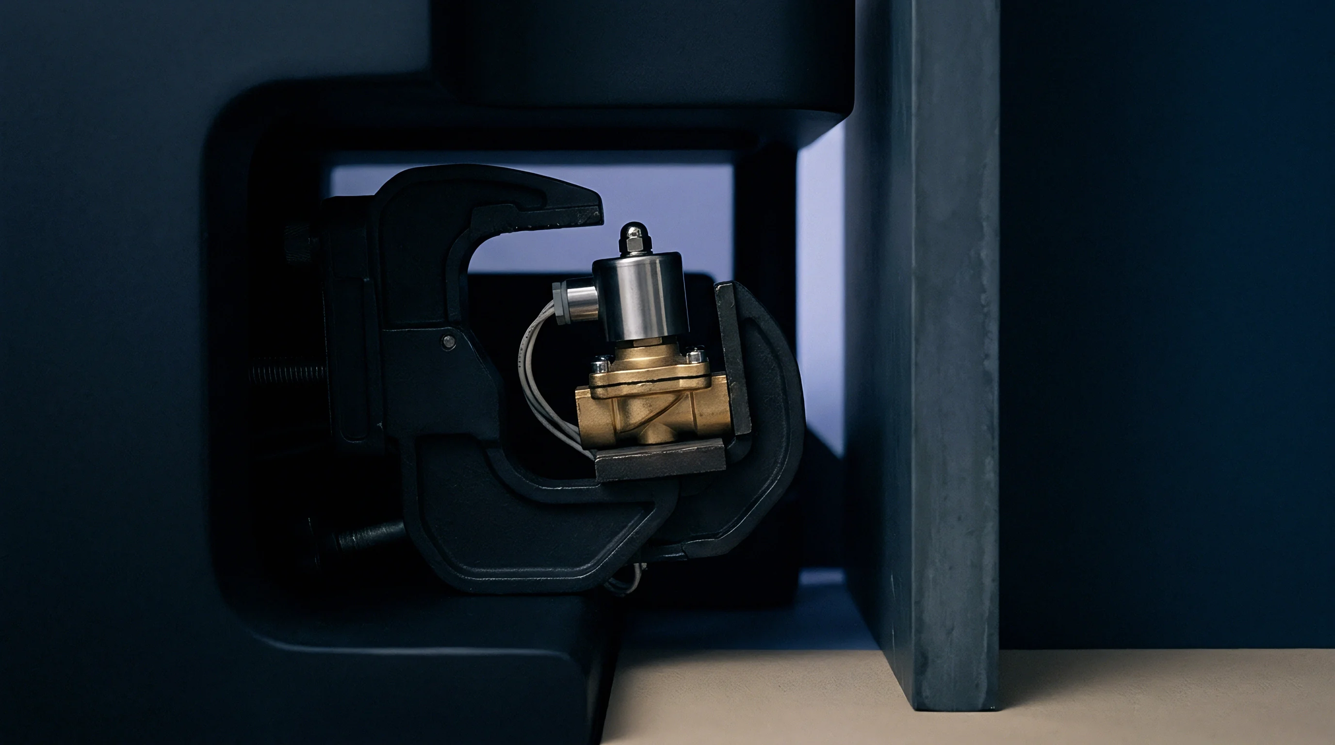
High-frequency dynamic monitoring demands instruments capable of tracking acoustic pressure fluctuations in harsh environments. Standard industrial pressure transmitters feature slow sensor diaphragms and internal oil-filled capillary tubes that damp signals above twenty Hertz. Dynamic regulation of close-coupled nozzles requires piezoresistive or piezoelectric dynamic pressure transducers with resonant frequencies exceeding fifty Kilohertz.
Mounting locations directly influence signal quality and frequency response bandwidth. Installing transducers far from the nozzle tip introduces phase shift and acoustic attenuation into dynamic readings. Positioning sensors close to the annular chamber while insulating them from extreme melt temperatures protects sensitive measurement electronics, using air-cooled or water-jacketed mounting blocks without dampening incoming gas pressure signals.

Where Does Signal Delay Compromise Pressure Regulation?
Physical separation between the sensing diaphragm and the atomization orifice introduces transmission lag into control loops. Pressure waves travel through gas at local acoustic velocity, which varies with gas temperature and molecular weight. A half-meter impulse line filled with ambient temperature argon introduces approximately 1.5 milliseconds of pure dead time before a pressure pulse reaches the sensor interface.
Control algorithms processing delayed feedforward signals issue correction commands out of phase with physical nozzle conditions. When correction signals arrive out of phase, valve movements amplify existing pressure waves rather than damping them out. Keeping signal acquisition delay under two milliseconds enables effective feedback control above one hundred Hertz.

Sensor Tap Geometry and High-Temperature Signal Isolation
Recessed port designs prevent direct exposure of sensitive measuring elements to radiant furnace heat and particulate contamination. However, recessed sensing cavities form Helmholtz resonators if port internal volumes and tap orifice diameters are improperly matched. Uncompensated cavity resonance creates artificial pressure peaks in signal data that do not exist inside the gas manifold.
Compliance with ISO 5167 differential pressure measurement standards enforces tap hole geometry tolerances within 0.05 millimeters to eliminate turbulence-induced signal distortion.
Designing sensor tap passages with minimal internal volume and smooth chamfered edges reduces boundary layer turbulence. Using flush-mount diaphragm sensors built from high-temperature silicon-on-insulator or gallium phosphate materials eliminates impulse tubes completely. Flush mounting allows direct, high-frequency sensing at internal gas manifold walls up to operating temperatures of seven hundred degrees Celsius.
Inserting standard ASME B40.100 grade 2A calibration clauses into the equipment purchase order shifts non-conformance liability for drift back to the instrument manufacturer.

Response
Control loop architecture dictates how fast the gas delivery system corrects for supply disturbances. Conventional Proportional-Integral-Derivative (PID) controllers operating in isolation struggle with time-variant non-linearities inherent to high-pressure dynamic gas expansion. Advanced regulation strategies combine high-speed feedback with model-based feedforward compensation to anticipate pressure perturbations before they disrupt plume stability.
Feedforward algorithms compute required valve adjustments based on real-time liquid supply measurements, melt head level sensor feedback, and target gas-to-melt ratio inputs. Combining feedforward actions with tight PID feedback loops reduces total setpoint settling time following process disturbances.
Closed-Loop PID and Feedforward Control Architectures
Combining feedforward compensation for liquid level changes with PID feedback loop adjustments stabilizes operating differential margins. The feedforward path handles fast, predictable shifts in liquid head pressure, while the feedback loop corrects for sensor drift, thermal expansion, and unexpected line resistance changes. Sampling rates for digital loop controllers must exceed ten Kilohertz to maintain stable loop gains.
Gain scheduling adapts controller sensitivity across broad operating regimes. Low supply pressures require higher proportional gains to move large valve volumes quickly, whereas high baseline pressures demand lower gains to prevent system overshoot. Adaptive gain scheduling ensures uniform dynamic stability from initial gas purge up to full-scale production throughput.
Operational control parameters require bounded tuning targets to maintain loop stability during rapid process shifts.
| Operational Mode | Sampling Frequency | Target Response Delay | Proportional Gain Range | Max Allowable Overshoot |
|---|---|---|---|---|
| System Startup Purge | 1.0 kHz | < 50.0 ms | 0.5 to 1.2 | 5.0% static pressure |
| Stable Melt Atomization | 10.0 kHz | < 2.5 ms | 2.8 to 4.5 | 1.5% static pressure |
| Dynamic Pulse Spraying | 25.0 kHz | < 0.8 ms | 5.0 to 8.5 | 0.5% static pressure |
| Emergency Abort Ramp | 5.0 kHz | < 10.0 ms | 1.0 to 2.0 | 0.0% static pressure |
Mass Flow Tracking during Variable Spray Deposition
Continuous spray processes demand dynamic gas density modification to maintain consistent powder particle size distribution. Varying liquid delivery mass flow requires immediate, proportional adjustments to atomization gas supply pressure. Closed-loop mass flow tracking prevents droplet size drift during extended production runs.
Pneumatic system response limits must match the maximum slew rate of liquid feed systems. Aligning control loops prior to production sign-off requires a systematic calibration sequence.
- Determine baseline line capacitance and dead time by applying step voltage changes to gas control valves while logging pressure response at the nozzle manifold tap.
- Adjust loop sample clock timing to achieve at least ten signal acquisitions within the fastest measured rising edge time.
- Configure feedforward gain matrices using empirical gas flow rate data gathered across the target operating pressure envelope.
- Optimize gain schedules iteratively under heated conditions to account for thermal expansion and shifting gas viscosity profiles.
- Validate dynamic suppression margins by injecting synthetic pressure pulses into upstream supply lines and measuring tip depression recovery rates.
Whether high-speed dynamic pressure modulation can totally eliminate satellite particle formation across all melt viscosity ranges without inducing acoustic resonance remains an open industrial question.


Integration
Commercial equipment specifications for atomization hardware establish boundary lines for engineering guarantees and capital expenditures. Atomization system performance relies on seamless integration between gas regulation hardware, nozzle head assemblies, and automated control logic. Equipment buyers must define exact scope boundaries between nozzle manufacturers, valve suppliers, and master system integrators to avoid gaps in warranty coverage.
Divided integration responsibilities increase risk during commissioning. When gas delivery systems fail to hold target dynamic pressure margins, valve vendors often blame nozzle manifold acoustic design, while nozzle suppliers cite gas supply header instability. Clear interface control documentation defines acceptable pressure ripple, signal bandwidth, and fluid cleanliness at every component junction.

Tooling Cost Boundaries and NRE Allocation
Non-recurring engineering expenses covering custom atomization nozzle geometry typically scale with precision machining tolerances and alloy grades. Precision close-coupled nozzles manufactured from specialized nickel-chromium alloys or high-density ceramic matrix composites demand tight tolerances, often specified within five micrometers on annular gap dimensions. Variations in gap dimensions across production lots alter local flow resistance, requiring individual nozzle flow calibration charts.
Amortizing non-recurring engineering costs across high production volumes requires standardizing base manifold connections while keeping tip geometry modular. Modular designs allow operators to replace worn nozzle tips without discarding expensive high-frequency pressure transducers and internal gas distribution channels. Purchasing standardized nozzle inserts lowers recurring maintenance costs and simplifies spare parts inventory management.

Equipment Performance Dossiers and Sourcing Ownership
Cross-border procurement contracts assign strict technical acceptance milestones before factory sign-off. The performance dossier must contain traceable pressure response curves, dynamic calibration records, and non-destructive test certificates for high-pressure gas channels. Equipment buyers retain final payment milestones until the complete assembly demonstrates continuous dynamic pressure regulation under full thermal load conditions.
Compliance documentation must explicitly define component ownership for certified pressure containment files under regional safety regulations. The master integrator takes sole responsibility for overall machinery safety filings, while individual component suppliers supply sub-tier material compliance certificates. Final acceptance sign-off occurs when the delivery package contains traceable dynamic pressure response logs, complete material certifications for atomization housing alloys, and signed operational warranty boundary schedules.