Nozzle Design and Argon Dynamics in Tool Steel Powder Atomization
Precise ceramic tip protrusion and supersonic argon aspiration stability dictate powder yield, preventing melt freeze-off and carbide segregation.

Tip
In close-coupled atomization, performance comes down to how ceramic delivery components position molten metal relative to high-pressure gas conduits. When processing high-alloy tool steels such as M35, M2, and CPM 10V, liquid metal feeds from an overhead tundish through a narrow delivery tube right into the focal point of converging inert gas jets. The exit tip sits directly inside this high-kinetic-energy gas stream.
Proper geometric alignment between the ceramic tip lip and the gas nozzle manifold dictates whether the stream atomizes cleanly or freezes off. Tool steel melts routinely exceed 1480 degrees Celsius, carrying significant carbon and alloy contents that alter viscosity and surface tension. Any minor physical degradation of the ceramic tip distorts gas expansion, disturbing the local pressure field and destabilizing the liquid stream before primary breakup begins.
Boron nitride, alumina-toughened zirconia, and graphite-bonded ceramics serve as primary materials for melt delivery tubes. Boron nitride is favored for its resistance to thermal shock and low wettability against liquid iron alloys. However, molten tool steel passing through the bore exerts mechanical shear while dissolved vanadium, chromium, and carbon cause chemical erosion at high temperatures.
During pilot runs with high-vanadium tool steel, BN tip erosion exceeded 0.15 millimeters after four operational hours. That slight geometric change widens the annular gap between the ceramic outer diameter and the gas nozzle exit ring, directly reducing gas jet momentum density right at the contact boundary.
Orifice Alignment
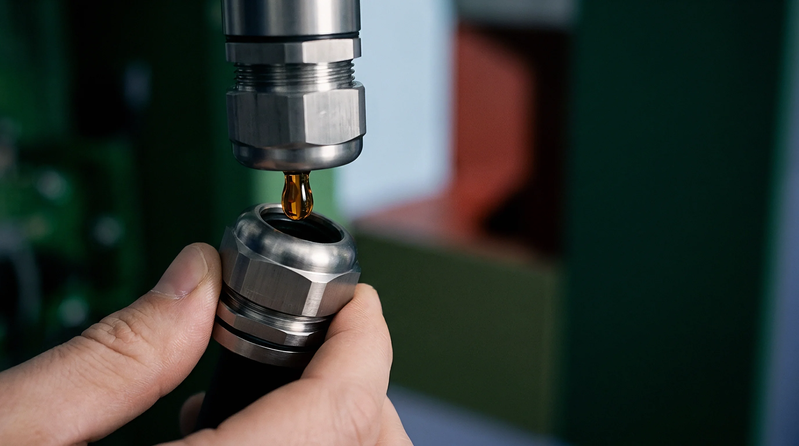
Melt delivery tubes constructed from dense boron nitride extend past the inner housing wall to meet converging argon jets. Radial concentricity between the tube outer wall and the surrounding gas nozzle orifice must stay within 0.02 millimeters. Asymmetric positioning creates an uneven gas mass flux around the liquid stream perimeter.
The side with the narrower gap sees locally elevated gas velocity, while the wider side lacks sufficient momentum transfer. Liquid tool steel then shifts toward the low-pressure region generated by this kinetic energy imbalance, producing non-uniform primary droplets that widen the overall particle size distribution and increase scrap during sieving.
The shape of the tip lip controls how gas detaches from the solid ceramic boundary. A sharp 90-degree corner at the tube exit forces flow separation, creating small recirculation eddies right next to liquid metal discharge. These eddies pull cold inert gas back against the ceramic wall, rapidly stripping heat from the melt until local temperatures drop below the alloy liquidus point and solid metal skulls freeze across the exit.
Tapering the outer edge with a 30-degree chamfer lets supersonic argon jets attach to the profile without premature boundary layer separation, keeping energy transfer steady across the interface while minimizing heat loss at the liquid exit plane.
ASTM B214 sieve verification combined with automated optical inspection isolates non-metallic inclusions originating from eroded delivery tube linings.

Conical Protrusion Depth
Positioning the exit face three millimeters beyond the primary gas manifold plane shifts the local static pressure distribution. This protrusion depth ~ the distance from the gas nozzle exit plane to the ceramic tip face ~ dictates whether the melt exit operates under positive or negative static pressure. Extending the ceramic tip too far downstream places liquid discharge past the gas focal point, where the stream encounters gas that has already expanded, weakening effective shear forces and producing coarse, non-spherical particles.
Recessing the ceramic tip inside the gas manifold housing creates severe recirculation against the nozzle face. Liquid metal drawn into this internal recess contacts cold ceramic surfaces, causing rapid solidification and bore blockage. Precision shims and micro-adjustment threads on the tundish mounting structure allow engineers to set protrusion depth within a tolerance of 0.05 millimeters.
Maintaining exact alignment preserves stable suction pressure over long production runs.
Melt stream instability reduces powder yield, with gas velocity determining droplet diameter, argon purity preventing surface oxidation, and thermal expansion altering BN nozzle clearances.
Thermal expansion during system preheating shifts initial mechanical alignments because structural steel housings expand faster than low-expansion boron nitride tubes. Preheating the atomization nozzle stack to 900 degrees Celsius before opening the tundish valve ensures mechanical dimensions match operational tolerances. Thermal equilibrium prevents ceramic stress cracking and maintains spatial alignment between gas orifices and the melt exit throughout pouring operations.
Delivery tip ceramic degradation involves both thermal exposure from the tundish and aerodynamic shear stress at the orifice exit.


Breakup
Molten tool steel exposed to supersonic gas streams disintegrates through rapid fluid mechanical instabilities. Upon exiting the delivery tube, the core remains intact briefly while surrounded by high-velocity argon. Energy transfer from the gas phase destabilizes the liquid column surface, initiating primary disintegration.
Wavy surface perturbations grow rapidly under aerodynamic drag forces, shearing sheets and filaments away from the central column. High liquid density in tool steel alloys demands substantial kinetic energy from argon streams to break cohesive metallic bonds before liquid droplets cool below their crystallization points.
Primary disintegration transitions into secondary droplet shatter within millimeters of the exit orifice. Sheared liquid filaments break down further as aerodynamic drag overcomes internal surface tension. The dimensionless Weber number ~ the ratio of gas inertia forces to liquid surface tension forces ~ governs this interaction.
Achieving effective secondary shatter requires local gas velocities exceeding Mach 2.0 at the point of contact. Large velocity differences between argon jets and moving droplets drive wave growth across individual liquid metal bodies, splitting them into micron-scale spheres.

Primary Filament Disruption
High-density M35 liquid alloy exiting the tundish nozzle encounters supersonic gas streams operating at Mach 2.2. Gas impact deforms the cylindrical liquid metal stream into a thin, expanding conical sheet. Aerodynamic drag induces Rayleigh-Taylor instabilities across the liquid-gas interface, with perturbations growing exponentially until the sheet breaks into continuous longitudinal ligaments.
High carbon and vanadium concentrations raise liquid viscosity, delaying sheet breakup and extending the distance needed for initial ligament separation.
Ligaments formed during primary disruption retain high aspect ratios as they travel downstream. High surface tension pulls liquid filaments into spherical forms, provided local cooling rates allow sufficient time before solidification begins. If argon mass flow falls short relative to metal mass flow, liquid filaments freeze into elongated, irregular rods.
Operating at gas-to-metal mass flow ratios between 2.0 and 3.5 provides enough thermal and kinetic energy to separate ligaments into small droplets while keeping them fluid during shape relaxation.
Higher liquid surface tension requires sharper gas jet apex angles to detach fine droplets before primary ligaments cool into irregular shapes.

Droplet Spheroidization Mechanics
Surface tension forces in liquid high-speed steel resist aerodynamic drag until the Weber number exceeds twelve. Once the local Weber number passes this critical threshold, droplets enter catastrophic breakup modes. Secondary shatter breaks larger liquid bodies into sub-50 micrometer fine droplets within microsecond timescales.
Rapid deceleration of fine droplets relative to the surrounding argon stream reduces local shear, allowing surface tension forces to draw distorted liquid droplets into true spheres.
Spheroidization time must remain shorter than droplet solidification time to guarantee spherical powder morphology. Small liquid droplets, possessing high surface area to volume ratios, lose thermal energy rapidly via convection to cold argon gas. Solidification rates reached during gas atomization of tool steels fall between 10,000 and 1,000,000 Kelvin per second.
If a droplet solidifies before surface tension rounds its surface, the particle retains a distorted shape, degrading flowability during additive manufacturing powder bed packing.
Nozzle wear shifts aspirator pressure profiles, elevated vanadium content increases melt viscosity, and cold argon lowers overall atomization efficiency.
| Argon Pressure (MPa) | Gas Velocity (Mach) | Gas-to-Metal Ratio | Median Diameter D50 (µm) | Fine Fraction <15 µm (%) |
|---|---|---|---|---|
| 2.0 | 1.45 | 1.30 | 78.4 | 4.2 |
| 2.8 | 1.85 | 1.95 | 48.2 | 11.6 |
| 3.5 | 2.25 | 2.70 | 31.5 | 22.8 |
| 4.2 | 2.60 | 3.45 | 22.1 | 36.4 |
Varying argon pressure alters gas density and expansion velocity at the nozzle exit plane. Elevating supply pressure from 2.0 to 4.2 MPa increases kinetic energy transfer, reducing median droplet size from 78.4 to 22.1 micrometers. High gas-to-metal ratios increase fine particle yields, but excessive gas flows generate violent turbulence inside the atomization zone.
Uncontrolled turbulence forces fine, semi-solid droplets back into the primary breakup spray, causing them to collide with larger liquid droplets.
Collisions between semi-solid fine particles and molten larger droplets create parasitic surface accretions. Solidified fines weld onto liquid surfaces, forming coarse particle clusters with irregular surface nodules. Parasitic accretions degrade powder apparent density and cause mechanical interlocking during automatic hopper feeding.
Controlling secondary gas flow fields downstream of the primary breakup zone prevents fine powder recirculation, preserving smooth particle surfaces across target size distributions.
Maintaining gas velocity above liquid stream sonic velocity prevents coarse filament formation regardless of minor alloy composition shifts.


Aspiration
Static pressure differentials developed at the melt exit control whether metal flows smoothly or back-streams into the refractory assembly. High-velocity argon expanding from close-coupled nozzle orifices induces a local vacuum directly beneath the ceramic delivery tip. This localized low-pressure zone, known as aspirator pressure, draws liquid tool steel through the bore.
Stable negative aspirator pressure prevents melt stagnation, maintaining continuous liquid mass flow from the tundish into the atomization chamber.
Fluctuations in aspirator pressure introduce dangerous operational instabilities. If static pressure beneath the delivery tip rises above ambient chamber pressure, positive back-pressure opposes gravity flow. Positive pressure drives gas into the tundish nozzle bore, forcing gas bubbles through molten tool steel.
Gas bubbling induces severe melt splashing, interrupts continuous liquid feeding, and can force molten steel upward around ceramic housing seals. Maintaining a consistent negative aspirator pressure between -10 and -30 kilopascals guarantees stable suction and uniform liquid pour rates.
Static Suction Differential
Gas velocities traversing the annular nozzle gap generate a localized low-pressure zone directly beneath the delivery tube exit. The magnitude of this pressure drop depends on argon supply pressure, jet convergence angle, and ceramic tip geometry. At lower gas pressures, flow separation along the ceramic wall creates unsteady pressure oscillations.
Oscillating suction causes liquid metal delivery rates to surge and drop, yielding inconsistent particle size distributions throughout single production runs.
In production trials, aspirator pressure monitoring operates on two-minute intervals. Transducers connected to pressure ports inside the nozzle housing record real-time static pressure variations during metal pouring. Sudden increases in aspirator pressure indicate ceramic erosion or partial melt freeze-off inside the delivery tip exit.
Real-time pressure monitoring allows operators to adjust argon supply valves dynamically, restoring stable suction before stream disruption occurs.
Operating at an aspirator pressure of negative eighteen kilopascals with argon preheated to three hundred degrees Celsius yields an eighteen percent reduction in fine droplet agglomeration.
Should Preheated Argon Replace Standard Cold Inflow?
Elevating gas temperatures to three hundred degrees Celsius before injection reduces thermal shocks across BN delivery channels. Standard cold argon expanding through supersonic nozzles drops in temperature due to Joule-Thomson expansion. Cold gas striking the ceramic tip extracts thermal energy from molten tool steel, increasing liquid metal viscosity at the exit boundary.
Heat loss at the tip lip causes localized freezing, gradually narrowing the delivery bore diameter during extended pours.
Preheating argon balances thermal losses, maintaining liquid tool steel temperatures above liquidus limits during atomization. Hotter gas increases gas volume and expansion velocity for a given mass flow rate, elevating dynamic kinetic energy at lower supply pressures. Preheated argon reduces gas density slightly, which alters aerodynamic drag coefficients, but reduced liquid metal viscosity offsets density changes.
Thermal management of gas streams prevents tip freeze-off, enabling continuous pouring operations exceeding six hours without manual nozzle clearing.
Tundish refractories are susceptible to thermal shock, while static pressure drop governs liquid melt velocity.
Delivery tube internal diameter directly interacts with aspirator pressure to establish steady-state melt flow velocity. A narrow 3.0-millimeter bore offers high flow resistance, requiring stronger negative aspirator pressures to maintain target mass flow rates. Expanding the bore to 6.0 millimeters increases liquid throughput but reduces internal fluid friction, making the stream susceptible to rapid drainage or aspirator-induced surging.
Matching bore geometry to gas nozzle aspirator profiles ensures controlled liquid delivery without manual valve throttling during atomization operations.
Uncontrolled aspirator pressure fluctuations during a twelve-ton production run forced the plant to scrap three batches of high-speed steel powder after metal back-streaming ruined the BN nozzle interface.


Chamber
Enclosed atomization towers maintain clean inert atmospheres while directing falling metal sprays toward bottom collection hoppers. As liquid metal droplets separate from the primary gas breakup zone, they enter the main chamber volume. Argon gas injected at the top nozzle expands into this large volume, creating global gas circulation patterns.
Tower diameter and height dictate whether cooling droplets solidify fully before striking chamber walls. Liquid droplets impacting solid structural walls flatten and adhere, forming thick metallic crusts that re-contaminate clean powder batches.
Inert atmosphere purity inside the collection volume protects reactive alloying elements in tool steel melts. Vanadium, chromium, and silicon oxidise rapidly when exposed to trace oxygen at temperatures above 1000 degrees Celsius. Operating towers under positive argon pressure with oxygen contents held below two parts per million prevents surface oxide scale formation.
Oxide-free powder particle surfaces ensure complete liquid phase melting during laser additive manufacturing, eliminating lack-of-fusion defects in printed tooling components.
Tower Gas Velocity Profiles
Recirculation loops inside vertical collection units draw fine powder back toward the active atomization plume. High-velocity primary gas jets drag surrounding chamber gas downward via momentum entrainment. Entrainment creates strong upward recirculation currents along tower walls.
Upward gas currents capture light, fully solidified fine particles smaller than 15 micrometers, lifting them back into the hot primary atomization zone.
Recirculated solid fines collide with semi-solid liquid droplets descending from the melt tip. The solid fine particle embeds into the molten surface, creating a permanent attached nodule upon complete cooling. Parasitic particle attachments degrade powder sphericity and alter packing behavior.
Introducing secondary argon shroud gas down chamber walls disrupts upward recirculation loops. Secondary gas shrouds force gas flows downward, carrying fine particles cleanly to collection hoppers without re-entering the primary spray zone.
| Secondary Argon Flow (Nm³/h) | Tower Oxygen Content (ppm) | Solidification Rate (K/s) | Attached Nodules per 1000 Particles | Hall Flow Rate (s/50g) |
|---|---|---|---|---|
| 0 | 1.8 | 4.5 × 10⁴ | 312 | 22.4 |
| 150 | 1.2 | 1.2 × 10⁵ | 145 | 18.1 |
| 300 | 0.8 | 2.8 × 10⁵ | 42 | 15.3 |
| 450 | 0.6 | 3.1 × 10⁵ | 38 | 15.1 |
Increasing secondary argon shroud flow from zero to 300 cubic meters per hour reduces attached surface nodules from 312 to 42 per thousand inspected particles. Secondary gas flow accelerates convective heat extraction, increasing solidification rates up to 280,000 Kelvin per second. Faster cooling refines internal microstructures and improves Hall flow rates from 22.4 to 15.3 seconds per fifty grams by eliminating surface irregularities.

Solidification Kinetic Control
Cooling rates exceeding one hundred thousand Kelvin per second prevent coarse carbide segregation in M2 tool steel. Slow cooling of tool steel droplets permits carbon, tungsten, and molybdenum to segregate into grain boundaries, forming coarse eutectic carbide networks. Coarse carbides resist dissolution during downstream heat treatment, reducing final tool toughness.
Rapid solidification traps alloying elements inside saturated iron matrices, suppressing primary carbide precipitation during flight.
Fine microstructures developed through rapid solidification yield uniform carbide dispersions upon heat treatment. Solidified droplets exhibit fine cellular or dendritic structures with interdendritic arm spacings under 1.5 micrometers. Rapid cooling also limits micro-segregation across individual powder particles, ensuring consistent chemical properties across every size fraction.
Homogeneous powder chemistry promotes uniform melting kinetics during additive manufacturing laser scanning cycles.
Recirculating argon eddies carry solidified fine particles directly back into liquid metal droplets before thermal solidification completes, promoting surface accretion.
Sieve screening separates usable size fractions, though fine powder can clog meshes and high argon purity remains critical throughout processing.
The exact velocity field threshold where secondary argon shrouding completely eliminates parasitic particle accretion without disturbing primary jet alignment remains uncertain across varying tower height ratios.

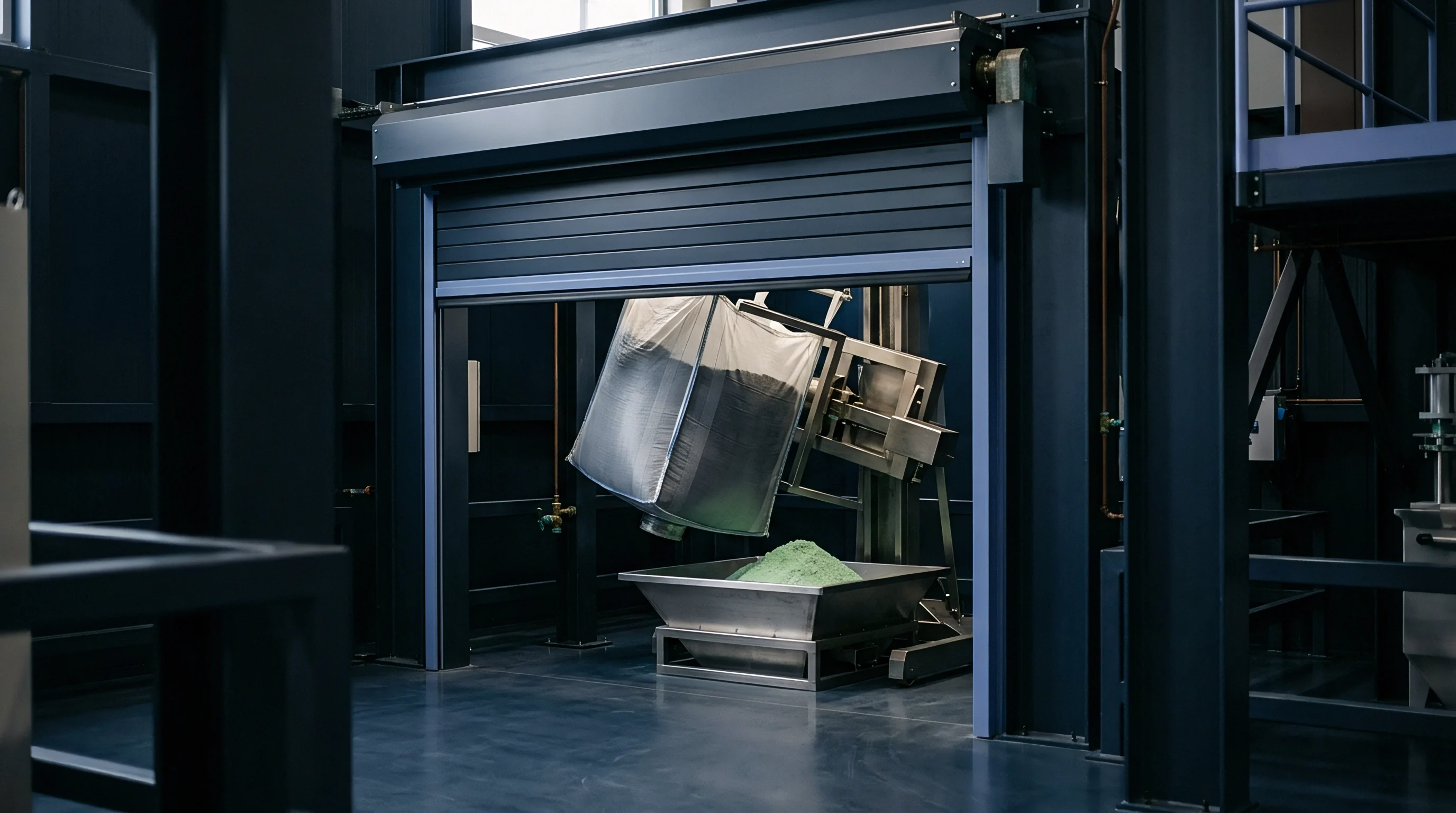
Yield
Target particle size distributions dictate the economic viability of gas-atomized tool steel powders used in additive manufacturing. Laser powder bed fusion applications require narrow particle size cuts, typically between 15 and 45 micrometers. Direct energy deposition processes utilize coarser cuts ranging from 45 to 150 micrometers.
Unusable oversized scrap exceeding 150 micrometers and ultra-fine dust under 15 micrometers lower prime yield, increasing production expenses per kilogram of usable powder.
Powder classification uses precision ultrasonic sieving and air classification circuits to separate crude atomized batches into target fractions. High-density tool steel powders pack tightly across screen meshes, causing mechanical blinding if sieving parameters are incorrect. Ultrasonic transducers attached to sieve frames introduce high-frequency micro-vibrations, breaking agglomerates and clearing blind mesh openings without damaging wire screen meshes.

Particle Size Distribution Ratios
Laser powder bed fusion processing requires powder diameter ranges strictly bounded between fifteen and forty-five micrometers. Powder containing excessive particles under 15 micrometers exhibits poor flowability, clogs reloader blades, and causes uneven powder bed spreading. Conversely, powder containing particles over 45 micrometers fails to melt completely under standard laser power settings, producing internal porosity defects in final printed components.
Adjusting gas atomization parameters to maximize the 15-to-45 micrometer yield fraction reduces post-processing scrap costs. Operating at gas pressures of 3.5 MPa with preheated argon shifts median droplet size toward 30 micrometers, yielding up to 48 percent of total pour weight within target LPBF specifications. When reviewing supplier test certificates, operators verify sieve calibration records against standard ASTM specifications.
Contractual adoption of ASTM B214 sieve testing protocols alongside automated image analysis eliminates disputable batch rejections based on particle shape variance.

Refractory Inclusion Screening
Sieve mesh separation combined with automated optical particle counting identifies non-metallic inclusions originating from tundish linings. Mechanical wear and thermal erosion detach microscopic fragments of zirconia, alumina, or boron nitride from delivery conduits. These non-metallic particles pass into the atomization spray, solidifying into foreign inclusions embedded within tool steel powder batches.
Refractory inclusions do not melt during additive manufacturing laser scanning. Inclusions remain as brittle ceramic voids inside fully dense tool steel components, acting as initiation sites for fatigue failure under cyclic mechanical loading. High-density liquid metal separation combined with automated optical inspection ensures powder lots meet stringent aerospace and tooling cleanliness standards prior to shipment.
- Lot Sampling Protocol ~ Extract representative ten-gram powder samples from five distinct vertical locations within each sealed five-hundred-kilogram storage drum.
- Sieve Analysis Execution ~ Mount stack sieves onto an ultrasonic frame, applying a 28 kilohertz excitation frequency for fifteen minutes under continuous nitrogen purge.
- Morphology Inspection ~ Transfer fine sieved fractions to an automated dynamic image analyzer, recording aspect ratio and sphericity metrics across 100,000 individual particles.
- Inclusion Detection ~ Disperse twenty grams of powder onto a polished optical plate, scanning under automated light microscopy to identify non-metallic inclusions larger than twenty micrometers.
Tool steel chemistry directly governs melt surface tension, while unplanned nozzle replacements interrupt line production.
Inserting an explicit upper limit of two refractory inclusions per hundred grams into powder purchase specifications shifts financial liability for premature filter blinding back to the atomization facility.

Overhead
Gas consumption and nozzle wear constitute the primary variable operating expenses in tool steel powder production. High-pressure argon gas represents up to 40 percent of total processing costs when operating without recycling systems. Inert gas consumption scales directly with gas supply pressure and nozzle throat area.
Minimizing specific gas consumption per kilogram of atomized metal requires tight control over liquid pouring rates and gas mass flow balances.
Nozzle tooling wear creates ongoing maintenance overhead during tool steel powder manufacturing. High-speed steel alloys containing tungsten and vanadium severely erode ceramic tip orifices, requiring frequent nozzle teardowns and rebuilding cycles. Tooling replacements consume expensive BN ceramics, incur manual labor costs, and cause production downtime that lowers overall plant throughput.
Argon Recovery Economics
Operating gas atomization equipment without closed-loop gas recycling adds three dollars per kilogram to direct processing costs. Closed-loop argon recovery systems capture exhaust gas from atomization towers, compressing and purifying the inert stream for continuous re-injection. Recovery plants utilize multi-stage compression combined with cryogenic distillation to remove oxygen, moisture, and fine metal dust contaminants accumulated during atomization flight cycles.
Efficient argon recovery systems recover up to 95 percent of consumed inert gas, dramatically lowering gas purchasing expenses. Maintaining gas purity above 99.999 percent inside recovery circuits requires continuous online dew-point and oxygen sensor monitoring. Contaminated argon recycled back into atomization nozzles oxidizes molten metal streams, ruining entire powder batches through surface oxidation.
| Cost Component | Without Gas Recovery ($/kg) | With Gas Recovery ($/kg) | Cost Share (%) |
|---|---|---|---|
| Virgin Alloy Raw Materials | 6.50 | 6.50 | 31.2 |
| Argon Gas Consumables | 4.80 | 0.48 | 2.3 |
| Ceramic Tooling & Nozzles | 1.25 | 1.25 | 6.0 |
| Electrical Power & Utilities | 1.10 | 1.85 | 8.9 |
| Sieve Scrap & Yield Loss | 4.20 | 4.20 | 20.2 |
| Labor & Plant Overhead | 6.55 | 6.55 | 31.4 |
Implementing closed-loop argon recovery reduces direct gas expenses from $4.80 to $0.48 per kilogram. Added compressor electrical power increases utility expenses slightly, but net operational cost drops by $3.57 per kilogram. Gas recovery systems transform high-pressure gas atomization economics, making high-alloy PM tool steel powders commercially competitive against traditional ingot metallurgy routes.

Commercial Qualification Terms
Purchase agreements for gas-atomized tool steel powder specify exact sampling procedures within each five-hundred-kilogram lot. Sourcing contracts outline strict limits on chemical composition, particle size distribution, apparent density, flowability, and gas content. Nozzle supply contracts specify strict erosion limits directly.
Defining clear liability boundaries for non-conforming powder lots protects buyers against costly production delays during additive manufacturing. Contracts stipulate that batch rejections based on oxygen contamination or poor flowability entitle buyers to full lot replacement and reimbursement for testing fees. Establishing rigorous quality verification standards guarantees reliable material inputs for high-performance tooling manufacturing applications.
Calculating total landed cost per kilogram requires adding argon compression power and sieve scrap conversion losses directly to raw alloy melt expenses.