Nonlinear Multi Axis Shear Fatigue Fracture Propagation in Hydrolytically Aged Structural Cell to Pack Adhesive Interfaces
Hydrolytic aging drastically reduces multi-axis fatigue thresholds in structural cell-to-pack adhesive interfaces, accelerating fatigue crack growth rates by orders of magnitude under cyclic road loads.


Moisture
Damp heat environments cause irreversible network degradation in the two-part polyurethane and epoxy adhesives used for cell-to-pack integration. Moisture penetrates the bondline through Fickian diffusion across the bulk polymer and wicks along the interface with the aluminium cell housing. Water breaks down the joint along two simultaneous paths: physical plasticization of the bulk resin and hydrolytic cleavage of primary chemical bonds.
During environmental cycling, humidity breaches the pack housing seals, pushing internal relative humidity beyond 85 percent at 60°C. Ingressing water molecules lodge in the cured resin’s free volume and interrupt inter-chain hydrogen bonding, dropping the glass transition temperature by 15°C to 30°C within 500 hours of exposure. Meanwhile, hydrolysis attacks ester, carbamate, and residual epoxide linkages in the backbone. The resulting chain scission permanently lowers crosslink density, turning what was a rigid, viscoelastic adhesive into a plasticized elastomer with a drastically lower tangent modulus.
The interface degrades alongside the bulk resin. Standard manufacturing relies on anodized or coated aluminium prismatics and pouch frames, where leftover contaminants, thin silane primer, or patchy plasma treatment leave unpassivated oxide sites on the metal. Moisture condenses in these interfacial micro-cavities and hydrolyzes the siloxane bonds anchoring the primer.
Under load, failure shifts from cohesive fracture through the adhesive core to clean, low-energy adhesive delamination at the cell surface.
Relative humidity levels above 80 percent at 60°C depress the glass transition temperature of two-part structural polyurethanes by up to 25°C within 500 hours of continuous exposure.
As the interface breaks down chemically, the bead loses its ability to transfer shear across the pack floor. This loss of structural capacity traces to several distinct mechanisms under continuous damp heat:
- Bulk plasticization expands free volume and increases chain mobility under cyclic load, cutting initial shear yield strength.
- Hydrolytic chain scission severs backbone bonds, permanently degrading the tensile and shear strength of the crosslinked matrix.
- Silane bond cleavage attacks organosilane coupling networks on the aluminium oxide, stripping adhesion away at the boundary.
- Substrate hydration transforms the aluminium oxide into a weak, friable pseudo-boehmite layer that fractures under slight shear strain.
Joint failures during qualification testing often trace to uncontrolled atmospheric conditions inside the assembly plant rather than defective resin batches. Uncured beads take up ambient moisture rapidly during open-time windows between dispensing and cell seating.
Constitutive Degradation Mechanics
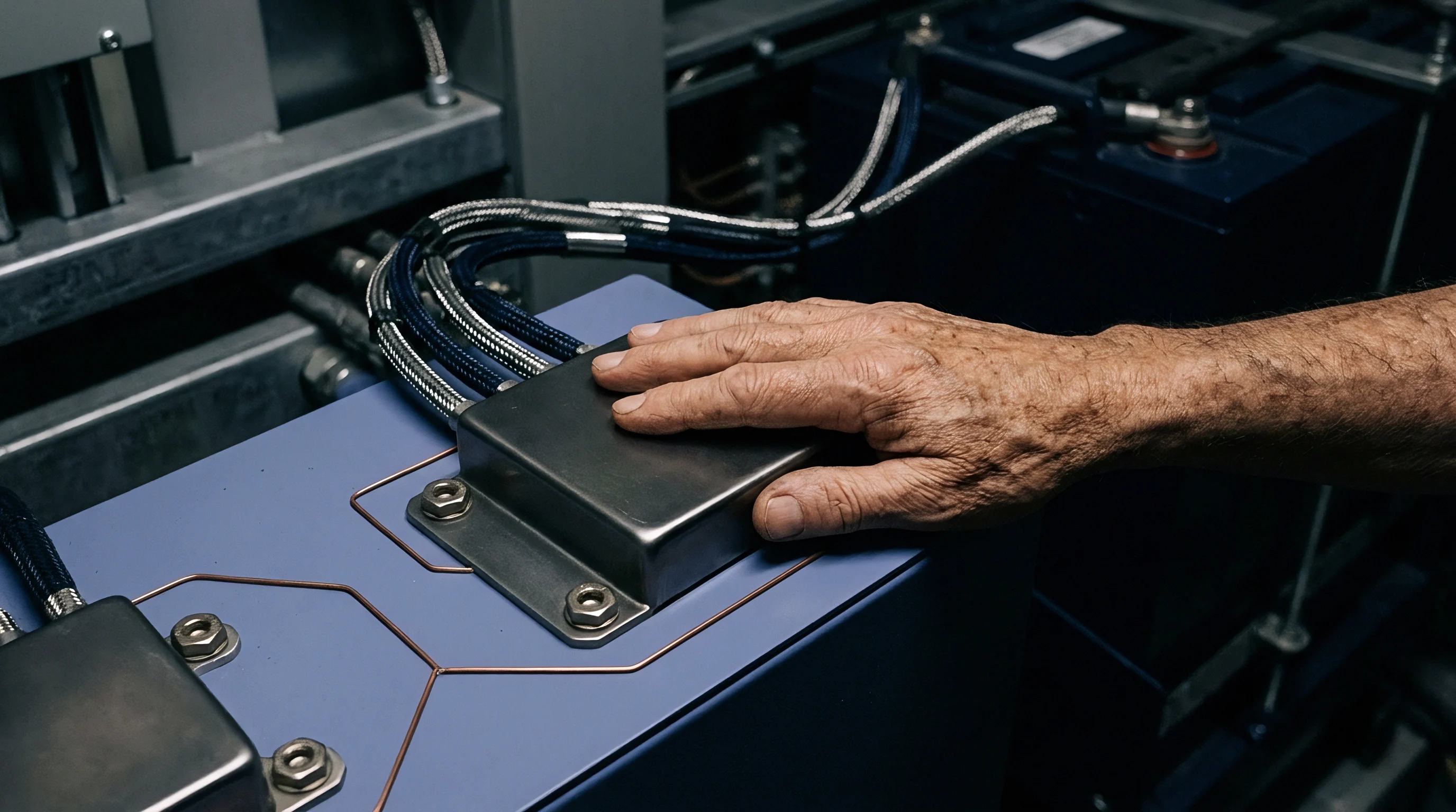
Hydrolytic aging shifts the constitutive response from linear viscoelasticity to pronounced non-linear viscoplasticity. Because severed polymer chains can no longer sustain continuous shear, stress relaxes quickly under quasi-static strain. Under dynamic cycling, however, the damaged bondline generates localized hysteretic heat.
This heat builds up within the low-conductivity polymer matrix, warming the bondline and accelerating moisture diffusion directly into the crack tip.


Traction
Vehicle operation subjects cell-to-pack joints to complex multi-axial stress. Torsional chassis deflection forces the adhesive beads into combined Mode II in-plane shear and Mode III out-of-plane shear, while cyclic swelling in prismatic and pouch cells imposes sustained Mode I normal tension across the bondline. Predicting whether a joint survives requires a coupled multi-axial traction-separation formulation that accounts for non-linear softening in every loading mode.
Cohesive zone models map normal and shear tractions against local displacement jumps across the bondline. Fresh adhesive exhibits high initial stiffness with linear or quadratic damage evolution, whereas aged material yields early, strain-hardens over wide displacements, and accumulates damage non-linearly.
| Adhesive Chemistry | Initial Shear Modulus (MPa) | Aged Shear Modulus (MPa) | Initial Mode I Fracture Energy (J/m²) | Aged Mode I Fracture Energy (J/m²) | Initial Mode II Fracture Energy (J/m²) | Aged Mode II Fracture Energy (J/m²) |
|---|---|---|---|---|---|---|
| Structural 2K Polyurethane | 450 ± 30 | 180 ± 20 | 1,450 ± 80 | 620 ± 45 | 2,100 ± 110 | 890 ± 60 |
| Toughened 2K Epoxy | 1,850 ± 90 | 1,200 ± 75 | 880 ± 50 | 410 ± 30 | 1,350 ± 70 | 680 ± 40 |
| Structural Acrylic | 320 ± 25 | 110 ± 15 | 1,120 ± 65 | 340 ± 25 | 1,600 ± 85 | 480 ± 35 |
Shear and normal tension interact strongly once strains enter the plastic regime. Pure Mode II shear forces polymer chains to slide past one another, but superimposed Mode I tension pulls the chains apart and cuts interfacial friction, accelerating that slippage. Mixed-mode fracture criteria therefore need interaction exponents that evolve as moisture penetrates deeper into the bondline.

Coupled Mixed-Mode Traction Formulations
Damage initiation in aged joints depends on the total equivalent displacement jump. Superimposed shear and normal tension lower the critical threshold where micro-voids coalesce into continuous cracks. While normal compression from cell expansion initially increases shear capacity through friction, cyclic load reversals quickly destroy that benefit once debonding begins at the interface.
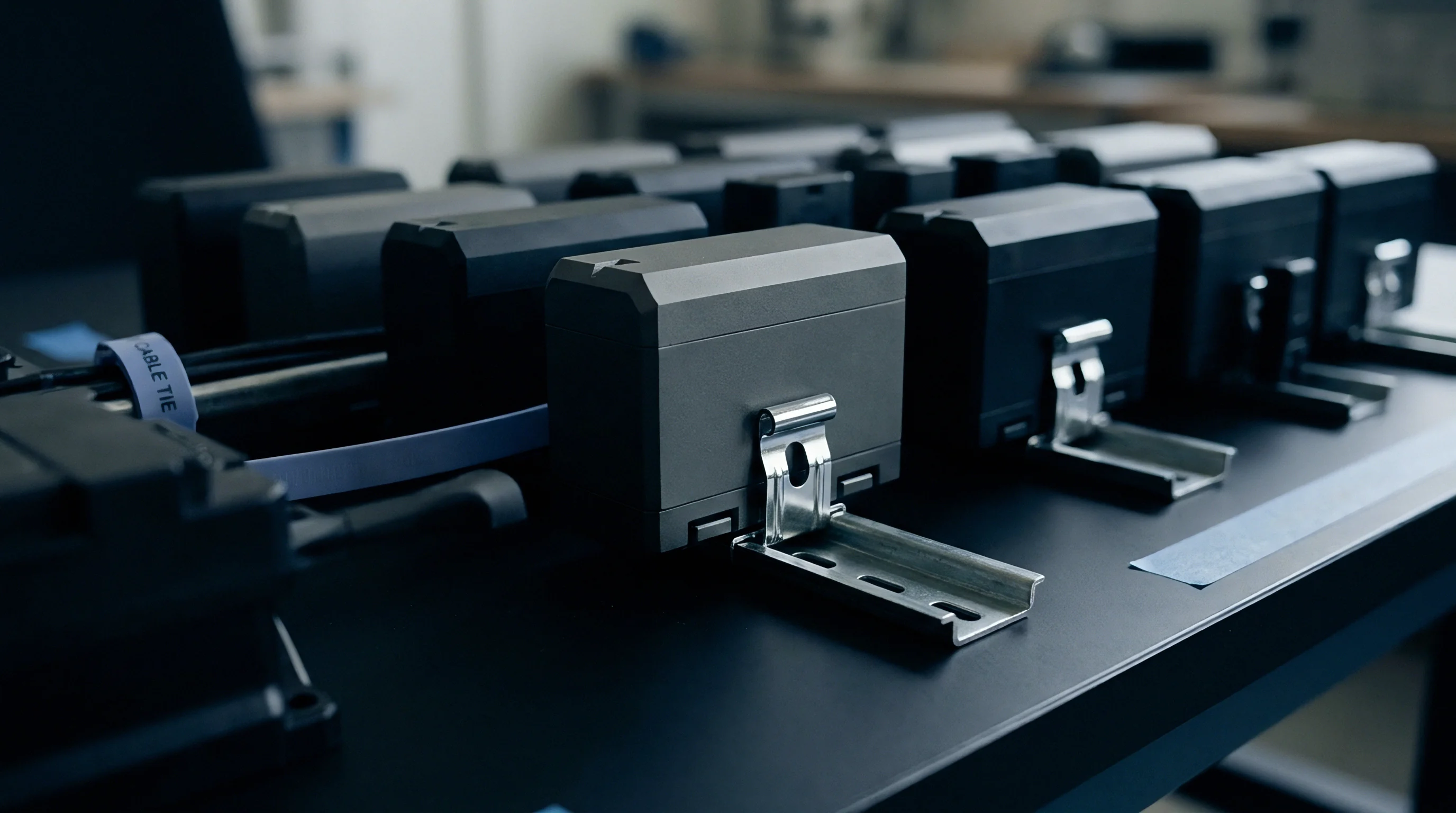
Thickness variations across large pack arrays make traction distributions uneven. Under a given displacement, thicker sections experience higher localized strains, concentrating shear deformation directly into zones already weakened by moisture.
When bond gaps vary across the pack floor, the thicker, moisture-softened patches absorb the bulk of cyclic shear fatigue.
Fracture
Road vibration drives fatigue cracks straight through the moisture-damaged adhesive interface. Over an operational lifetime, cell-to-pack bonds accumulate millions of variable-amplitude shear cycles. Because hydrolytic breakdown robs the polymer of its energy dissipation capacity, crack growth rates accelerate by orders of magnitude at the same applied strain energy release rates.
Paris Law formulations link cyclic crack propagation rates to the applied strain energy release rate range. When adhesive hydrolyzes, these power-law parameters shift aggressively: the threshold strain energy drops, allowing manufacturing micro-voids and small interfacial flaws to spread into full crack fronts under normal driving vibration.
| Condition State | Multi-Axis Shear Energy Range ΔG (J/m²) | Threshold Strain Energy Range ΔGth (J/m²) | Paris Law Exponent m | Paris Law Constant C | Calculated Cycles to Failure (10 mm Crack) |
|---|---|---|---|---|---|
| Unaged Baseline | 150 | 115 | 3.4 | 1.2 × 10⁻⁸ | 2.8 × 10⁶ |
| Aged 500h (85/85) | 150 | 48 | 5.1 | 4.6 × 10⁻⁷ | 3.1 × 10⁵ |
| Aged 1000h (85/85) | 150 | 22 | 6.9 | 8.9 × 10⁻⁶ | 1.4 × 10⁴ |
| Calculated values assume a constant shear strain amplitude under dual-axis fatigue testing at 10 Hz frequency. | |||||
Fatigue damage moves through distinct stages from initial void growth to complete joint separation:
- Moisture concentrates in microscopic voids and low-crosslink pockets within the cured resin.
- Cyclic multi-axial shear stresses nucleate micro-cracks at the edges of these voids.
- Micro-cracks link across hydrolytically weakened chains, forming a continuous crack front.
- The crack advances along the substrate interface under modest energy release rates.
- The remaining intact bond area overstresses and shears apart completely under peak vehicle loads.
Under ISO 12405 structural fatigue testing, hydrolytically degraded adhesive joints lose over 90 percent of their multi-axial fatigue lifecycle before macroscopic debonding becomes visible.

Quantitative Fatigue Crack Growth Sensitivity
At a cyclic shear strain energy release range of 150 J/m², fresh adhesive operates close to its threshold of 115 J/m², extending so slowly that a 10 millimeters crack requires more than 2.8 million cycles. After 1,000 hours of aging at 85°C and 85 percent relative humidity, chain scission drops that threshold to 22 J/m² and raises the Paris exponent from 3.4 to 6.9.
Because cyclic loads now sit far above the fatigue threshold, the crack tears across the same 10-millimeter distance in only 14,000 cycles under identical conditions. That collapse in fatigue life causes joints to separate abruptly during normal driving.
Ignoring how hydrolytic aging degrades multi-axial fatigue thresholds risks pack structural failure, cell rupture from unconstrained swelling, and torn high-voltage busbars in the field.


Fixture
Process control on the plant floor governs joint durability as much as resin formulation does. Tolerance stack-up between cell casing dimensions, tray flatness, and robotic dispense paths dictates the geometry of the cured bead. Any dimensional irregularity creates localized stress concentrations that speed up both hydrolytic ingress and mechanical fatigue.
Substrate surface preparation is the first line of defense against moisture-driven debonding. Raw aluminium casings arrive coated in rolling oils, unstable native oxides, and handling soils that prevent adhesive wetting. High-speed inline atmospheric plasma burns off hydrocarbon films and introduces polar groups across the aluminium, raising surface energy above 56 mN/m.
- Plasma treatment speed governs polar group density on the metal and dictates bond strength retention before moisture exposure.
- Open-time limits prevent dispensed beads from absorbing ambient humidity before cells are seated.
- Bondline thickness control keeps adhesive depth within tolerance to avoid localized stress peaks.
- Cure temperature profiles secure full crosslinking so unreacted species cannot wash out under humid operating conditions.
Dispense systems require tight control over flow rates and bead profiles to avoid trapping air. Entrained bubbles act as sharp internal notches under shear and double as condensation reservoirs for moisture. Automated vision stations inspect bead height, width, and path continuity immediately before the placement gantry sets cells into wet adhesive.
Atmospheric plasma surface treatment must elevate aluminium casing surface energy above 54 mN/m to prevent early moisture wicking along structural interfaces.

Dimensional Stack-Up Control
Mechanical tolerance stack-up across a 60-cell module can shift joint gaps from 0.8 millimeters to 3.5 millimeters along the same bondline. Overly tight gaps over-constrain the joint, producing high peel stresses during thermal expansion. Excessively wide gaps reduce joint shear stiffness and trap voids during low-pressure dispensing.
Production cells regulate these gaps using precision positioning tooling fitted with dynamic force feedback.
Vehicle supply agreements routinely classify any production lot with more than five percent interfacial delamination across structural bond areas after damp heat testing as a non-conformance carrying direct recall liability.


Bench
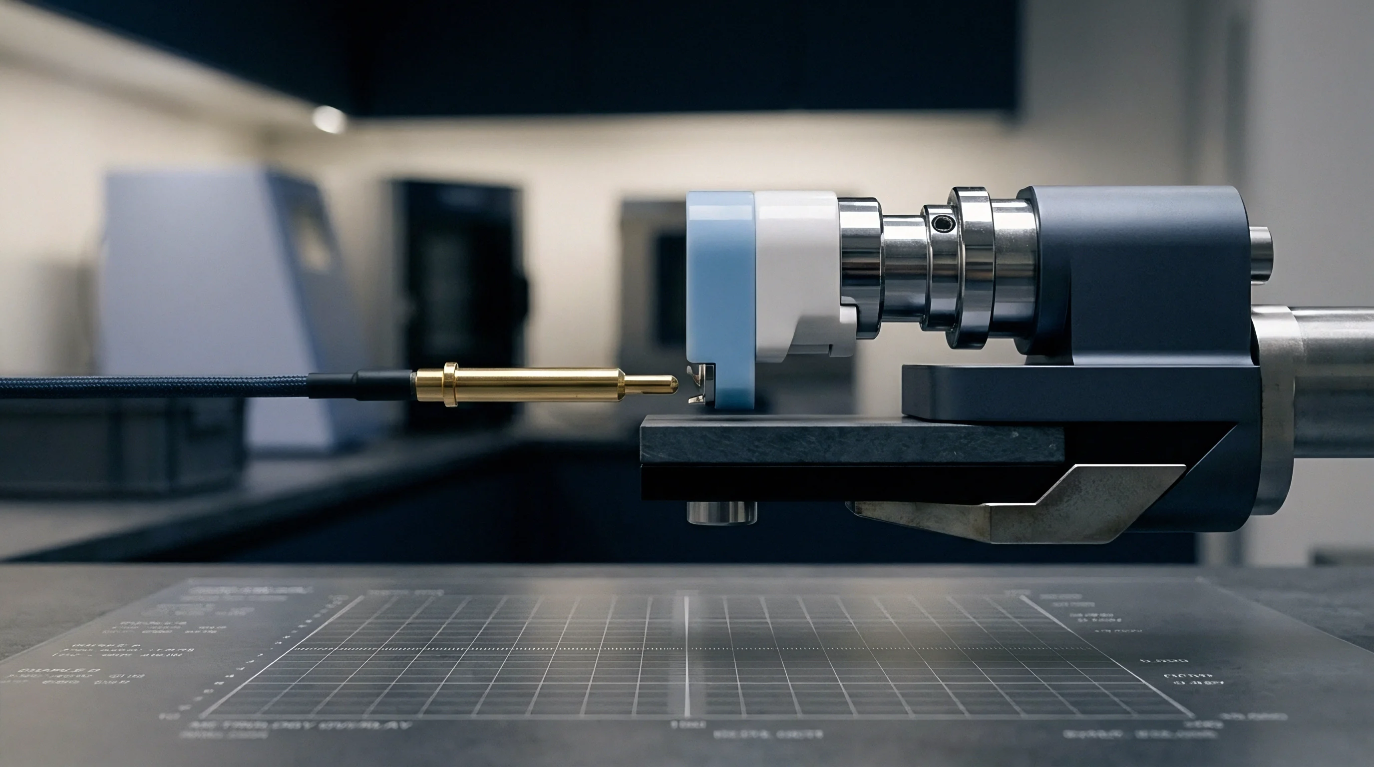
Measuring multi-axial fatigue propagation along aged interfaces requires dedicated bench setups. Standard lap-shear coupons cannot replicate the triaxial stress fields or moisture kinetics found inside structural battery enclosures. Dedicated test fixtures must isolate pure shear while introducing dynamic biaxial displacement vectors.
Dual-actuator servo-hydraulic frames apply synchronized axial tension and high-frequency shear to conditioned specimens. Test coupons are pre-aged in environmental chambers following IEC 60068-2-78 temperature and humidity profiles. Modified Double Cantilever Beam and End-Notched Flexure rigs enclosed in environmental chambers then track mixed-mode fracture energy in real time.
| Test Methodology | Primary Mechanical Mode | Measured Fracture Parameter | Sensor Tracking Resolution | Environmental Control Bounds |
|---|---|---|---|---|
| Dual-Axis Servo Fatigue | Mode II Shear + Mode I Tension | Multiaxial Paris Law Parameters (C, m) | ± 0.5 N Force / ± 1 µm Displacement | -40°C to +90°C / 10% to 98% RH |
| Modified End-Notched Flexure | Pure Mode II In-Plane Shear | Critical Shear Strain Energy (G_IIC) | High-Speed DIC 5.0 MP Resolution | Ambient to +85°C Submerged |
| Mixed-Mode Bending (MMB) | Variable Mixed Mode I/II | Mixed Mode Fracture Envelope (G_I/II) | Acoustic Emission Event Detection | Controlled Moisture Pre-Conditioning |
Digital Image Correlation maps surface strain across the exposed bondline edge under cyclic load. By tracking fine speckle patterns applied to the joint, high-resolution cameras calculate displacement fields and locate the crack tip well before macroscopic separation occurs.

How Do Biaxial Test Vectors Predict Continuous Joint Crack Growth?
Biaxial frames translate real-world road load data into synchronized actuator strokes. Paired shear and normal cycling rotates principal stress vectors inside the bead, deflecting cracks along hydrolytically weakened interfacial planes. Meanwhile, acoustic emission sensors on the cell wall detect the transient elastic waves emitted by micro-crack jumps, measuring crack growth rates accurately over millions of cycles.
Reliable laboratory verification requires strict control over test parameters from pre-conditioning to failure:
- Equilibrate test samples in climate chambers until mass gain levels off below 0.05 percent over 48 hours.
- Mount pre-aged specimens in zero-backlash mechanical grips aligned within 0.02 millimeters to prevent parasitic bending moments.
- Initialize DIC systems with calibrated lighting and verified speckle contrast before starting cyclic loading.
- Run cyclic tests below 15 Hz to prevent hysteretic self-heating within the polymer matrix.
- Log force and displacement continuously at high sampling rates to catch the sharp stiffness drops that signal rapid crack growth.
Correlating 85°C/85% RH damp heat hours to real-world vehicle operating years remains an open engineering problem, especially under fluctuating sub-ambient service conditions.
Warrant
Commercial agreements for cell-to-pack integration split technical risk across complex commercial boundaries between cell maker, adhesive supplier, and pack integrator. If bondlines delaminate in service, assigning liability depends entirely on documented conformance to qualification standards and validated process windows.
The pack integrator owns joint geometry, structural FEA modeling, and plant-floor surface preparation. The adhesive vendor guarantees minimum property retention bounds under specified hydrolytic exposures. Clear supply contracts specify the exact property drop-off thresholds where resin failure triggers vendor liability.
Start-of-production sign-off requires extensive validation dossiers: UN 38.3 vibration testing, ECE R100 Rev 3 structural crashworthiness data, and ISO 12405 environmental aging results. Managing warranty exposure demands direct traceability from the individual pack serial number back to plant dispense records, inline surface energy measurements, and resin batch lot certificates.
Tooling NRE for cell-to-pack lines routinely covers automated plasma systems, inline vision metrology, and controlled cure tunnels. Cutting capital costs on surface activation equipment might save upfront budget, but it exposes the OEM to crippling recall exposure if moisture debonds the packs in service. Defining technical boundaries early in supply contracts prevents drawn-out commercial disputes when fatigue cracks eventually challenge aged interfaces.