Structural Die Steel Metallurgy and Mold Life Degradation Mechanics
Structural tool steel longevity requires controlling matrix phase dynamics, thermal fatigue, and erosion to eliminate part tolerance stack-up and warranty disputes.


Carbide
Deep drawing 0.3 mm nickel-plated steel for cylindrical cell cans and impact extruding 1.0 mm aluminum alloys for prismatic battery casings put severe tribological stress on tooling inserts. Tool steels commonly specified for these dies—H13 (1.2344), D2 (1.2379), P20 (1.2738), S7, and specialized powder metallurgy grades like CPM-10V or Vanadis 4 Extra—depend on specific microstructural phases to survive millions of compression cycles. Running stamping presses at 180 strokes per minute pushes local contact pressures at the punch radius past 1200 MPa.
Under that level of localized stress, the geometry, volume fraction, and dispersion of hard precipitate phases dictate whether the die face maintains its profile or spalls.
Primary vanadium and molybdenum precipitate networks form during solidification and will not dissolve during standard austenitizing treatments. Secondary precipitates—mostly chromium-dense M7C3 and M23C6 structures—dissolve and re-precipitate during high-temperature tempering. Mechanical stability in a deep-drawing punch requires preventing continuous networks from gathering along prior austenite grain boundaries.
In aluminum module frame casting tools cycling rapidly between 200 degrees Celsius and 680 degrees Celsius during high-pressure die operations, coarse grain-boundary networks create severe stress concentrations. Cracking initiates along these brittle interfaces inside 15,000 thermal cycles if raw stock exhibits micro-segregation worse than Band 2 on the SEP 1614 scale.
Cold forming aluminum battery enclosures demands a compromise between fracture toughness and abrasion resistance. Standard D2 steel contains up to 12 percent chromium and 1.5 percent carbon, generating primary M7C3 islands that average 15 to 25 micrometers across. These massive carbides resist sliding abrasive wear against unlubricated sheet metal, but they act as internal notch sites under fatigue loading.
Switching to a powder metallurgy matrix reduces precipitate clusters below 2 micrometers, eliminating the micro-cracking sites that shear off punch tips during tight corner draws.

Alloy Matrix Composition in High Volume Stamping Tools
Selecting the alloy chemistry for a high-volume cell can die involves balancing working hardness against impact toughness. Standard AISI H13 resists thermal fatigue through its 5 percent chromium, 1.3 percent molybdenum, and 1 percent vanadium content, holding a bulk hardness of 48 to 52 HRC. However, that hardness falls short in long-run ironed wall drawing dies, where the working surface must remain under Ra 0.05 micrometers to prevent sidewall galling.
Those drawing stations require cold-work steels with higher carbon levels to push working hardness past 60 HRC.
The table below compares five common structural tool steel grades used in battery tooling, detailing their chemistry, working hardness ranges after heat treatment, and main failure modes in continuous production.
| Steel Grade (AISI / DIN) | Key Alloy Elements (Weight %) | Hardness (HRC) | Charpy V-Notch Impact (J) | Primary Microstructural Hard Phase | Dominant Degradation Mode |
|---|---|---|---|---|---|
| H13 / 1.2344 | Cr 5.0, Mo 1.3, V 1.0, C 0.4 | 46 – 52 | 18 – 24 | MC and M23C6 dispersion | Thermal fatigue checking |
| D2 / 1.2379 | Cr 12.0, Mo 0.8, V 0.9, C 1.5 | 58 – 62 | 5 – 8 | Coarse primary M7C3 | Edge micro-chipping |
| P20 / 1.2738 | Cr 1.9, Ni 1.2, Mo 0.4, C 0.4 | 28 – 34 | 35 – 50 | Tempered martensite matrix | Compressive yield deformation |
| S7 / 1.2355 | Cr 3.2, Mo 1.4, C 0.5 | 54 – 58 | 25 – 35 | Low volume carbide matrix | Galling and adhesive wear |
| CPM-10V | V 9.75, Cr 5.25, Mo 1.3, C 2.45 | 60 – 64 | 10 – 14 | Discrete vanadium MC phases | Polishing loss and erosion |
Under cyclic impact, high-chromium tool steels micro-fracture along rolling bands where hard phase clusters align. In cylindrical can drawing, a 10-micrometer chip on the draw ring radius cuts parallel gouges through the casing’s nickel layer. That breach leaves the cold-rolled steel vulnerable to moisture over pack life, accelerating galvanic corrosion.
Preventing this defect requires raw bar stock for drawing inserts to undergo 3D forged reduction ratios of at least 4 to 1, breaking up directional segregation before vacuum heat treatment.

Metallurgical Phase Dynamics across Tool Steel Classifications
Phase transformation kinetics during heat treatment govern whether finished die blocks retain dimensional stability. Quenching high-alloy steels from austenitizing temperatures between 1020 degrees Celsius and 1060 degrees Celsius leaves retained austenite in the martensitic matrix. Under cyclic stress at room temperature, this retained austenite is metastable; repetitive stamping impacts trigger transformation into fresh, untempered martensite, producing roughly 1 percent volume expansion.
At contact pressures above 1000 MPa, an 8 percent retained austenite level expands punch neck diameters by 12 micrometers in just 50,000 cycles.
That uncontrolled growth disrupts tight die clearances. In pouch cell laminate forming, where tooling draws aluminum polymer film into 3 to 6 mm pockets, tool clearances are held between 15 and 25 micrometers. A 12-micrometer swell pinches the protective polypropylene layer, opening micro-pinholes along corner radii.
Moisture migrating through those fissures reacts with lithium hexafluorophosphate electrolyte to generate hydrofluoric acid inside the cell. To keep retained austenite below 1 percent, parts require cryogenic treatment down to minus 196 degrees Celsius immediately following quench.
Sub-zero processing forces residual austenite to convert into martensite before final tempering passes. Skipping it allows dimensions to drift over six months of storage or across early production runs. Pouch-forming die sets have lost 18 micrometers of clearance over 80,000 strokes after an omitted sub-zero cycle, despite double-tempering having met nominal bulk hardness specifications.
- Carbide Stringer Micro-cracking happens when coarse primary phase networks align with mechanical rolling directions, leading to premature shear failure parallel to the draw axis under high impact.
- Retained Austenite Transformation causes unexpected expansion of die inserts in production, shifting clearances and tearing thin metal sheet.
- Secondary Hardening Precipitate Coarsening drops matrix yield strength when die surfaces run above the final tempering temperature, leaving permanent indentations along core radii.
- Grain Boundary Decohesion occurs during severe thermal shock in high-pressure die casting, where intergranular networks embrittle prior austenite grain boundaries.
Failing to control phase dynamics cuts mold operating life by over 60 percent. Tooling procurement specifications must mandate certified microstructural analysis—including grain size verification to ASTM E112 Grade 8 or finer—on every heat of steel allocated for precision battery tooling. Bulk hardness readings alone do not register localized microstructural flaws, grain boundary networks, or unstable retained phases.
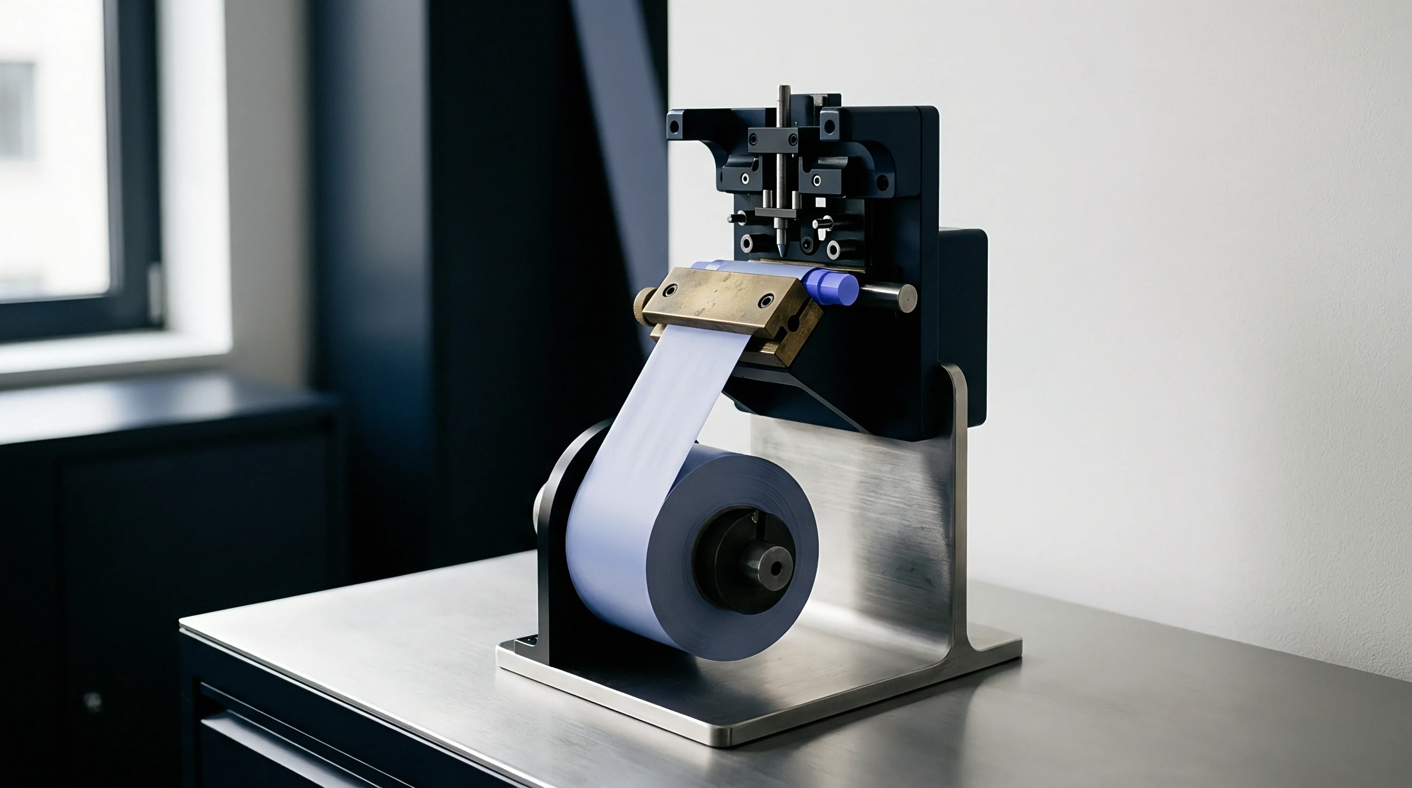

Temper
Proper heat treatment converts raw annealed tool steel into a stable, crack-resistant structure capable of holding tolerances across millions of hits. The cycle begins with controlled preheating to minimize thermal gradient stresses across complex cavities. In a 450-kilogram H13 die casting mold insert, preheating is conducted in two stages, at 650 degrees Celsius and 850 degrees Celsius, before ramping to the final austenitizing setpoint of 1020 degrees Celsius.
Heating too rapidly through the phase transformation zone induces internal stress gradients that warp or fracture the block during quench.
Vacuum hardening with high-pressure nitrogen gas quenching at 6 to 10 bar provides the cooling velocity needed to prevent pro-eutectoid network phases from precipitating along grain boundaries. The cooling curve must bypass the pearlite and bainite transformation noses on the time-temperature-transformation diagram. Slow gas cooling produces a soft matrix with grain-boundary networks that compromise Charpy impact toughness, whereas aggressive oil quenching introduces high residual surface tension that invites early thermal fatigue checking during hot metal injection.

Thermal Processing Steps for Tooling Stress Relief
Achieving peak toughness and dimensional stability requires multiple high-temperature tempering cycles. Secondary hardening steels like H13 and D2 reach peak hardness when coherent alloy carbide nanostructures precipitate between 500 degrees Celsius and 560 degrees Celsius. A single temper leaves high residual stresses and untempered martensite formed from transformed retained austenite.
Tool steel specifications require at least three separate tempering passes, held for a minimum of two hours at temperature plus an additional hour for every 25 millimeters of section thickness.
- Vacuum preheat die components at 650 degrees Celsius, ramping no faster than 220 degrees Celsius per hour to equalize core temperatures.
- Ramp furnace temperature to 850 degrees Celsius and hold for 45 minutes to stabilize austenitic transformation across varying wall thicknesses.
- Austenitize at 1020 degrees Celsius for 30 minutes under vacuum to prevent surface decarburization and oxidation.
- Quench with high-purity nitrogen gas pressurized to 8 bar, maintaining a cooling rate above 28 degrees Celsius per minute down to 60 degrees Celsius.
- Soak quenched parts cryogenically at minus 180 degrees Celsius for four hours to push retained austenite below 0.5 percent.
- Perform triple tempering cycles at 540 degrees Celsius, 560 degrees Celsius, and 550 degrees Celsius, cooling to room temperature in air between passes.
Stress relief during tool fabrication is equally critical. Rough machining induces plastic deformation extending up to 0.5 mm beneath the surface. Vacuum hardening a die block containing residual machining stresses causes distortion that exceeds allowable grinding stock.
Tool fabrication sequences require a dedicated stress relief cycle at 650 degrees Celsius for two hours following rough milling, prior to finish EDM or hard milling.

Surface Nitriding and Deposition Layers
Optimizing cavity tribology involves surface engineering after bulk heat treatment. Plasma nitriding and physical vapor deposition (PVD) coatings create hardened barriers while preserving core toughness. Plasma nitriding diffuses atomic nitrogen into the steel surface between 480 degrees Celsius and 520 degrees Celsius, creating a diffusion zone beneath a thin compound layer of iron nitrides.
This process raises surface hardness from 50 HRC to over 1000 HV, curbing adhesive wear and galling during high-speed drawing of steel or aluminum stock.
Per ISO 15787 specifications, plasma nitrided surface layers must restrict the brittle white compound layer thickness to less than 2 micrometers to prevent surface flaking under impact load.
Thick white layers consisting of brittle epsilon-phase nitrides fracture readily under cyclic impact. If an un-nitrided punch draws nickel-plated steel for 21700 cell cans, galling initiates within 20,000 cycles; transferred nickel or aluminum debris welds to the tool steel and scores the casing walls. Applying a duplex treatment—plasma nitriding followed by a 3-micrometer titanium aluminum nitride (TiAlN) PVD coating—increases surface hardness to 3200 HV while lowering the friction coefficient to 0.35 against bare sheet steel.
That duplex coating extends punch life in cylindrical can drawing from 150,000 cycles to beyond 2,000,000 before repolishing is required. However, the surface layer depends entirely on the core substrate for mechanical support. If the core steel is tempered below 48 HRC, high contact stress triggers local elastic-plastic deflection; the brittle PVD layer cannot accommodate the strain and spalls off.
Furnace atmospheres must remain strictly controlled to avoid surface decarburization. Decarburization depletes carbon from the outer 0.1 to 0.5 mm during heat treatment, leaving a soft ferrite matrix precisely where surface stresses peak. The affected zone can drop up to 20 HRC below the core, rendering subsequent nitriding or PVD treatments ineffective and establishing initiation points for early fatigue failure.
Furnace time-temperature charts record chamber conditions rather than the actual microstructure, case depth, or residual stress state of the finished tooling. Tooling purchase contracts protect quality by releasing final payment only after independent metallurgical inspection confirms grain size, retained austenite content, and case microhardness gradients per ASTM E384.


Fatigue
Structural die components subjected to repeated thermal and mechanical cycling degrade via thermomechanical fatigue. Casting tools for aluminum battery enclosures experience thermal excursions spanning several hundred degrees Celsius every 45 to 60 seconds. When molten aluminum at 670 degrees Celsius enters the cavity, the surface layer expands rapidly against the restraint of the cooler core, generating compressive stresses that surpass the hot yield strength of the steel.
Subsequent cooling spray quenches the surface to 200 degrees Celsius, shifting the stress state from compression into high tension. Repeating this reversal across thousands of cycles accumulates plastic strain at the surface. Micro-cracks initiate at grain boundaries, inclusions, and EDM heat-affected zones, forming an interconnected network termed thermal checking.
This surface degradation transfers raised aluminum ridges onto the cast tray, preventing correct gasket seating.

Which Alloy Modification Retards Cyclic Thermal Cracking?
Lowering silicon while increasing molybdenum and vanadium content improves thermal fatigue resistance. Standard H13 contains up to 1.0 percent silicon, added for melt fluidity and oxidation resistance during smelting. However, silicon reduces hot ductility and accelerates crack propagation under thermal cycling.
Premium hot-work grades such as H13 ESR, with silicon restricted below 0.30 percent, deliver twice the impact energy and fracture toughness of standard melts at 600 degrees Celsius.
Electro-slag remelting (ESR) refines the alloy by removing non-metallic sulfide and oxide inclusions that serve as crack initiation sites. Premium ESR steels exhibit near-isotropic mechanical properties, maintaining transverse impact toughness within 90 percent of longitudinal values. By contrast, conventional air-melted steels can lose up to 50 percent of their impact toughness in the transverse direction, leaving them vulnerable to cracking along rolling bands.

Thermomechanical Stress Waves in Battery Enclosure Dies
Mechanical fatigue acts in tandem with thermal stress in high-speed stamping and impact extrusion tooling. In the impact extrusion of prismatic aluminum cans, the punch experiences transient compressive stress waves exceeding 1400 MPa upon contact, followed by tensile rebound during retraction. This cyclic stress spectrum initiates micro-cracks at geometry transitions, particularly the shoulder between the shank and the forming tip.
Finite element analysis indicates that a 0.5 mm shoulder radius produces a stress concentration factor (Kt) of 2.4. Increasing that transition radius to 2.5 mm lowers Kt to 1.2, extending operating life from 250,000 to over 1,500,000 strokes under identical loading. Unpolished grinding marks act as stress risers, initiating fatigue cracks five times faster than a polished surface.
- EDM Recast Layer Cracking occurs when white layers from electrical discharge machining are left behind, letting micro-cracks propagate into the matrix under load.
- Thermal Gradient Shocking stems from aggressive spray cooling on cavities above 400 degrees Celsius, driving surface tension past the steel’s ultimate tensile strength.
- Mechanical Notch Sensitivity speeds up fatigue failure when tight fillets and machining grooves concentrate stress beyond the endurance limit.
- High-Temperature Softening happens when die surfaces run hotter than their final temper temperature, dropping yield strength and accelerating plastic deformation.
Electrical discharge machining leaves a brittle, untempered recast layer—the white layer—riddled with micro-cracks and tensile residual stress. Leaving a 15-micrometer recast layer on a stamping die can induce fatigue cracking in as few as 5,000 strokes. Removing this layer via polishing or chemical etching, followed by stress relief at 50 degrees Celsius below the final temper temperature, is essential to die longevity.
Fatigue progression follows a defined sequence: initiation, micro-crack coalescence, macro-crack propagation, and final fracture. Optical surface inspections during routine maintenance detect checking networks before cracks migrate into critical sealing lands. Blending out crack tips and re-nitriding the cavity restores fatigue resistance and prevents catastrophic failure during volume production.
Will advancing pulse-laser surface cladding allow targeted repair of micro-cracked radii in the shop without warping large battery enclosure molds?


Erosion
Surface erosion results from combined mechanical wear, liquid metal wash, and chemical attack. Aluminum battery tray casting dies experience severe wash adjacent to gate runners, where alloy containing up to 11 percent silicon enters at velocities exceeding 40 meters per second and pressures up to 90 MPa. This high-velocity melt scours away protective surface oxides, exposing the bare tool steel to chemical attack and erosive wear.
Soldering develops when molten aluminum reacts with iron in the H13 substrate, producing brittle Fe-Al intermetallic compounds like Fe2Al5 and Fe3Al that bond to the die surface. Ejection of the casting tears out micro-fragments of tool steel adhered to the part. Over tens of thousands of cycles, this repetitive pluck-and-tear mechanism pits the steel near gate entries and compromises component tolerances.
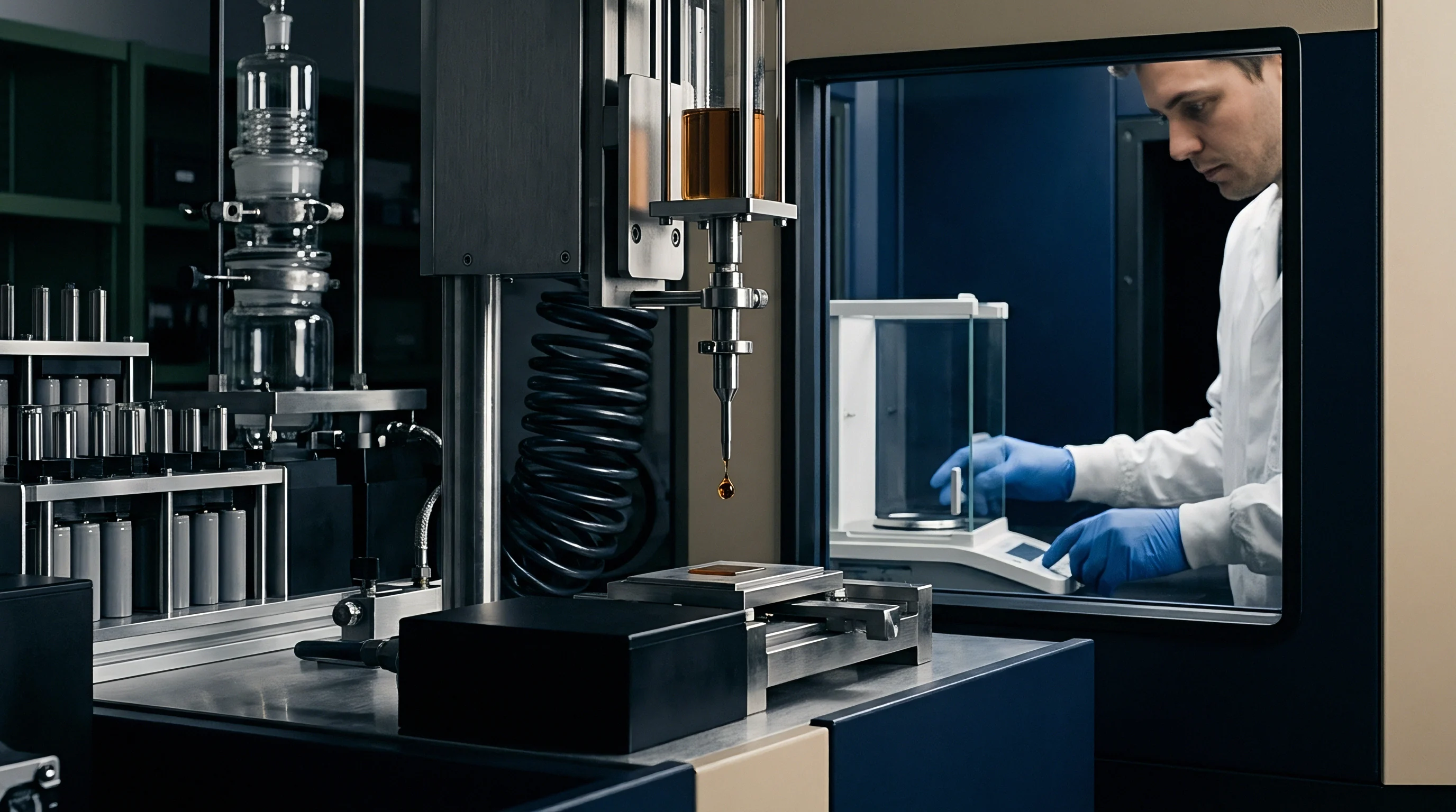
Polymer off Gassing and Liquid Metal Wash
Tooling for plastic battery frames, cell carriers, and cover enclosures experiences severe chemical erosion. Engineering polymers like flame-retardant polybutylene terephthalate (PBT), 30 percent glass-filled polyamide 66 (PA66), and polyphenylene ether (PPE) process at melt temperatures up to 300 degrees Celsius. Under high shear, brominated and organophosphate flame retardants degrade into corrosive off-gases, including hydrobromic and phosphoric acids.
These acidic vapors condense onto cooler cavity walls during part solidification and ejection, driving intergranular pitting along steel grain boundaries. Simultaneously, suspended glass fibers scour the corroded surface like micro-abrasive media. This coupled corrosive-abrasive wear pattern degrades high-polish cavities into dull, rough surfaces within 100,000 cycles.
Standard non-stainless tool steels like P20 or H13 corrode rapidly under acidic vapor exposure. Fabricating cavity inserts from martensitic stainless grades such as AISI 420 (1.2083) or Stavax ESR (13 to 17 percent chromium) establishes a self-passivating chromium oxide film that resists acidic attack. Heat treating 420 stainless to 52 ~ 54 HRC balances acid resistance with abrasion resistance, preventing vent channel clogging and preserving parting line shut-offs.

Cavity Degradation and Surface Wear Patterns
Wear in battery module injection molds concentrates at gate orifices, thin ribs, and flow restrictions. Forcing glass-filled polymer through gates under 1.0 mm drives local shear rates past 10,000 s^-1 (10,000 inverse seconds). Glass fibers orient with flow vectors, scouring directional micro-grooves into the steel.
Once surface roughness exceeds Ra 0.4 micrometers, parts bind during ejection, causing pin push-through and structural warpage.
Applying physical vapor deposition (PVD) CrN coatings to 420 stainless steel cavities lowers abrasive wear rates by 85 percent when processing 30 percent glass-filled flame-retardant polymers.
Chromium nitride (CrN) and diamond-like carbon (DLC) coatings provide chemically inert barriers against both acidic condensates and glass fiber abrasion. A 4-micrometer CrN PVD coating resists halogenated flame-retardant off-gassing while providing surface hardness above 2000 HV. Coating gate blocks and core pins extends scheduled maintenance intervals from 50,000 to beyond 400,000 cycles, keeping ejection forces within press limits.
Inadequate mold venting quadruples local wear rates. Vent channels positioned at melt convergence points require depths held strictly between 0.015 mm and 0.025 mm to evacuate air without permitting resin flash. When vents become plugged with degradation residue, incoming melt compresses trapped volatiles adiabatically.
Temperatures within the pocket exceed 800 degrees Celsius—diesel effect combustion—pitting the tool steel, generating carbon soot, and accelerating localized erosion.
Neglected vent channels during a run of glass-filled PBT module covers resulted in a 42,000 USD tooling rebuild when acidic condensate ate through parting line shut-offs, producing flash that prevented automated pick-and-place grippers from seating parts downstream.


Tolerance
Tool wear and structural distortion translate directly into dimensional drift on finished battery components. In high-speed can stamping, ironing dies must maintain internal diameter tolerances of plus or minus 0.005 mm across millions of cycles. As carbide or hardened steel draw rings wear, the working inner diameter expands, increasing cell wall thickness from the nominal 0.30 mm specification up to 0.33 mm.
A 0.03 mm increase in the wall thickness of a 21700 cell reduces internal volume for the jelly roll. Inserting a standard electrode assembly into an undersized cavity risks tearing the separator and causing internal shorts during winding. If the dimensional drift instead manifests as oversized outer diameter, cans jam inside automated cell holders, stopping pack assembly lines.

Part Dimensional Drift Stack up Mechanics
High-pressure die-cast aluminum battery trays exhibit multi-axis tolerance stack-ups as tooling deteriorates. Die wash, parting line erosion, and thermal checking distort local geometry throughout the cast structure. Thermal distortion of large inserts degrades flatness across module mounting faces—a 0.15 mm flatness specification across 1200 mm can degrade past 0.60 mm as core inserts deform under thermal cycling.
The table below provides a detailed tolerance stack-up and wear progression matrix, illustrating how steel degradation modes affect critical dimensions across three major battery manufacturing tooling applications.
| Battery Component | Tooling Application & Steel Grade | Primary Degradation Mechanism | Initial Tool Tolerance (mm) | Degraded Tool Tolerance (mm) | Downstream Assembly Consequence |
|---|---|---|---|---|---|
| 21700 Cell Can Casing | Deep Drawing Ring (CPM-10V) | Abrasive polishing loss & galling | +0.002 / -0.000 | +0.025 / -0.000 | Cell outer diameter oversized; module holder insertion jam |
| Prismatic Can Housing | Impact Extrusion Punch (H13 ESR) | Punch tip yield & corner chipping | +0.010 / -0.010 | +0.080 / -0.020 | Corner radius thinning; lid laser welding burn-through |
| Module Structural Frame | Injection Mold Cavity (420 SS) | Glass fiber erosion & vent pitting | +0.030 / -0.030 | +0.180 / -0.050 | Parting line flash; automated cell stack displacement |
| Structural Pack Tray | HPDC Mold Core (H13 / 1.2344) | Thermal checking & die wash | +0.100 / -0.100 | +0.450 / -0.200 | Mounting surface non-flatness; thermal pad gap void creation |
Uneven mounting lands leave irregular gaps between prismatic module bases and the cooling plate. When gap dimensions exceed the bridging capacity of the thermal interface material (TIM), interfacial thermal resistance increases. Varying TIM thickness between 0.5 mm and 2.2 mm across a single module row generates a 14 degrees Celsius temperature gradient across adjacent cells under 3C fast-charging conditions, accelerating cell degradation and triggering early BMS power derating.

Tooling Sign off Checklist for Acceptance
Controlling tolerance stack-up requires formal tooling sign-off protocols prior to accepting production molds. First-article inspection reports must evaluate parts produced under steady-state production conditions rather than hand-sampled prototypes. Evaluating parts at true thermal equilibrium reveals core shifts, uneven cooling shrinkage, and press deflection that short sampling trials mask.
- Cavity Pressure Profiling confirms that internal pressure transducers record uniform packing across multi-cavity molds, preventing uneven shrinkage.
- Laser Scan Dimensional Mapping compares complete 3D surface point clouds of molded parts against CAD models to spot thermal warpage across large components.
- Parting Line Flash Measurement checks mold clamping alignment under peak injection or intensification force to prevent sealing land defects.
- Tool Steel Hardness Mapping checks microhardness across high-wear radii and core pins to verify surface coatings and temper cycles hit spec.
Preventing downstream quality issues requires strict replacement limits tied to process capability (Cpk) thresholds. When Cpk drops below 1.33 on critical dimensions—such as prismatic lid seats or busbar alignment features—the tool must be pulled for refurbishment. Running worn tooling to delay maintenance expenses results in scrap, line downtime, and pack integrity failures downstream.
Tool maintenance schedules should track stroke counts against dimensional drift trends. Tooling protocols require non-destructive evaluation, such as dye penetrant or ultrasonic inspection, on critical radii every 100,000 cycles to identify surface micro-cracks before complete structural failure occurs.
Tool wear always shows up on the finished part before it destroys the die.


Lien
Commercial terms defining tooling ownership, non-recurring engineering (NRE) amortization, and maintenance reserves protect buyers from supply disruptions and unbudgeted capital expenditures. In cross-border tooling agreements, legal title to custom tooling—including cell can drawing dies, pouch forming plates, and pack enclosure molds—must vest with the buyer upon payment of initial NRE milestones. Contract terms must separate title from physical possession, establishing the buyer as sole legal owner while the supplier retains custody under a bailment framework.
Suppliers frequently bundle tooling NRE into component piece-part pricing, amortizing costs across target volumes such as 500,000 battery modules or 5,000,000 cell cans. If production falls short of contractual forecasts, suppliers may assert an unamortized tooling lien, withholding dies or refusing maintenance until the remaining balance is paid. Supply contracts require milestone-based step-down amortization schedules so title equity transfers unambiguously with each delivered lot.

Commercial Tooling Ownership and Maintenance Reserves
Tooling life warranties form the foundation of commercial protection. Agreements should warrant minimum operational life thresholds—commonly 1,000,000 strokes for cold-work stamping dies and 100,000 cycles for aluminum casting tools—prior to major refurbishment. Contracts must delineate routine maintenance from major rebuilds, assigning financial responsibility for replacing worn core inserts, chipped punches, or washed gate blocks to the supplier if the tool fails prematurely.
Establishing a structured maintenance reserve provides financial stability across multi-year programs. Withholding a set percentage from each part invoice—typically 1.5 to 3.0 percent of landed unit cost—into an escrow account ensures capital is available for refurbishment. These funds disburse only for scheduled overhauls, coating renewal, and verified crack repairs upon submission of certified toolmaker invoices and dimensional inspection reports.

Warranty Seams in Contracted Tooling Guarantees
Disputes frequently arise across the commercial interfaces between raw steel mills, commercial heat treaters, PVD coating centers, and the toolmaker. When a die casting core insert fails after 20,000 cycles, liability fractures across competing explanations: non-metallic inclusions in the mill stock, improper quench rates from the heat treater, or unremoved EDM recast layers left by the toolmaker.
Eliminating these disputes requires establishing single-source liability within the tooling procurement contract. The primary mold builder must bear complete warranty responsibility for tool performance, covering steel sourcing, thermal processing, surface treatments, and sub-tier qualification. Requiring a complete metallurgical dossier—including mill heat certs, furnace time-temperature charts, cryogenic processing logs, and microhardness depth profiles—ensures traceability to a single responsible vendor.
Contracts should stipulate that in the event of premature tooling failure, the toolmaker must machine replacement inserts at their own expense within a strict window—typically 14 business days—to prevent pack assembly stoppages. Tooling agreements must reserve the buyer’s right to conduct unannounced physical audits of the supplier’s tool room. Continued physical custody of the tooling remains conditional upon maintaining operational logs, quality certifications, and dimensional capability standards throughout the program life.