Mechanochemically Coupled Solid Electrolyte Interphase Plasticity and Stack Pressure Degradation Dynamics
Optimal pouch cell retention requires dynamic stack pressure containment between 0.3 and 0.8 MPa to absorb silicon anode swelling without separator collapse.

Mechanics
During initial intercalation, electrodes experience localized strain fields reaching twenty percent. In high-capacity silicon-graphite anodes, lithiation expansion creates heavy mechanical stress where active particles meet the liquid electrolyte. Solid electrolyte interphase films ~ formed as organic solvents and salt anions undergo electrochemical reduction ~ must accommodate these continuous shape changes as the host anode breathes.
Mechanochemically coupled plasticity describes how this surface layer simultaneously yields, flows, and fractures under local stress and active reduction.
When active particles deform faster than the passivation film can accommodate, micro-cracks open across the layer. Fresh metallic lithium or lithiated silicon is exposed directly to the liquid electrolyte. Immediate chemical reduction occurs, consuming active lithium inventory and solvent molecules to reform the passivation film over the newly exposed surfaces.
This dynamic balance between mechanical rupture and electrochemical re-passivation dictates the rate of irreversible capacity loss in advanced lithium-based battery formats.
Chemo-Mechanical Stress Fields at the Anode Interface
Intercalating lithium into silicon-graphite particles sets up steep internal concentration gradients. Higher concentration at the shell than the core induces tensile stress at the outer surface during lithiation, which flips to compressive stress upon de-lithiation. These particle-scale stresses propagate straight into the overlying interphase layer.
Inorganic constituents such as lithium fluoride and lithium carbonate exhibit high elastic moduli exceeding fifty gigapascals, rendering them mechanically brittle. Organic constituents, including lithium ethylene dicarbonate and polymeric species, display lower elastic moduli below five gigapascals and show pronounced viscoelastic creep behavior. The physical arrangement of these components within a mosaic or layered interphase structure determines whether localized strain resolves through plastic yield or brittle cracking.
The passivation surface deforms irreversibly under cyclic volume changes long before bulk active material pulverizes.
Viscoelastic Deflection of Layered Interphases
Passivation layers consist of distinct inorganic inner deposits and organic outer reaction products. The inner layer, adjoining the metallic or lithiated anode surface, bears high compressive stresses during volumetric swell. The outer organic layer interfaces directly with the bulk electrolyte solution, absorbing shear forces induced by fluid flow and localized swelling gradients.
Under cyclic mechanical loading, the outer organic matrix exhibits strain-rate-dependent plastic deformation. Slow charging rates allow viscoelastic relaxation of internal stresses, reducing the peak mechanical stress experienced across the interphase film. Accelerated fast-charging rates elevate peak interfacial shear stress, accelerating mechanical fracture of the inorganic inner layer.
Rapid capacity roll-off in pouch formats often stems from module over-constraint rather than interphase shear rupture.

Yield
Volume expansion in silicon-graphite composite particles can push local shear stresses in passivation films beyond two hundred megapascals. When internal shear stresses surpass the yield strength of the interphase components, irreversible plastic deformation occurs. This permanent alteration of interphase geometry changes both the ionic conductivity of the surface film and its structural integrity across subsequent cycles.
Nanomechanical Characterization of Passive Surface Films
Atomic force microscopy nanoindentation reveals broad variance in elasticity across interphase components. Nanomechanical testing confirms that inorganic species provide mechanical resistance against compressive loads, while organic oligomers absorb shear energy.
| Component Species | Young’s Modulus (GPa) | Yield Strength (MPa) | Fracture Toughness (MPa m^0.5) | Deformation Mode |
|---|---|---|---|---|
| Lithium Fluoride (LiF) | 55.0 to 65.0 | 350 to 450 | 0.8 to 1.1 | Brittle Fracture |
| Lithium Carbonate (Li2CO3) | 30.0 to 40.0 | 180 to 240 | 0.5 to 0.7 | Micro-cleavage |
| Lithium Ethylene Dicarbonate (LEDC) | 2.0 to 5.0 | 25 to 45 | 0.1 to 0.3 | Viscoelastic Creep |
| Poly-ethylene Oxide Matrix | 0.5 to 1.5 | 8 to 15 | 0.2 to 0.4 | Plastic Yield |
Plastic deformation in the organic outer layer alters the spatial distribution of ionic conduction channels. Dense packing of organic chains under compressive load increases local activation energy for lithium-ion transport, elevating interfacial charge-transfer resistance. Concurrent cracking in the brittle inorganic inner layer creates pathways for liquid electrolyte intrusion.
Continuous decomposition cycles build thick, heterogeneous interphase crusts that slow lithium transport.
- Interphase Micro-cracking Exposure of fresh anode surface leads to continuous electrolyte consumption and gas generation.
- Lithium Trapping Active lithium ions become permanently isolated within thickening organic breakdown products.
- Pore Collapse High local compressive forces close ionic transport channels through the inorganic matrix layer.
- Electrolyte Creep Dry-Out Liquid solvent moves away from localized pressure points into dead spaces within the stack.
Thick interphases formed at low temperatures crack faster under high mechanical compression than thin interphases grown during thermal formation.

Clamp
Module enclosures apply continuous normal forces to maintain physical contact across cell layers. Stack pressure dynamics govern the balance between mechanical integrity and electrochemical performance in pouch and prismatic cell formats. As anode active materials expand during charge, the overall thickness of the cell stack increases.
If the external containment structure is rigid, internal swelling forces convert directly into elevated stack pressure. If the external containment is overly soft, electrode layers delaminate, causing localized impedance spikes and accelerated lithium plating.

What Pressure Window Maximizes Silicon Anode Retention?
Capacity retention shifts sharply when gas pressure and silicon volume changes ~ silicon expands three hundred percent ~ work against external containment. Unconstrained silicon-graphite pouch cells suffer rapid capacity drop within two hundred cycles due to electrode delamination and electrical isolation of active particles. Applying a baseline stack pressure between zero point three and zero point eight megapascals maintains particle-to-particle electronic contact without crushing the porous separator structure.
Silicon-graphite pouch cells held at 0.5 MPa static pressure exhibit twice the cycle life of unconstrained cells cycled under identical 1C rate conditions.
Dynamic Compression Trajectories across Cycle Life
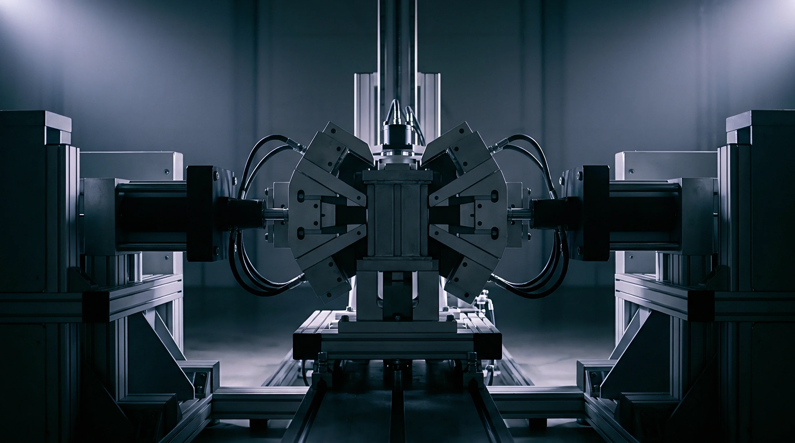
Volumetric expansion over hundreds of charge-discharge cycles drives progressive displacement against module boundary structures, where rigid plates magnify swelling stresses while foam pads absorb cyclic expansion.
To quantify the difference between structural constraint approaches, consider a 60 Ah silicon-graphite pouch cell containing fifteen percent active silicon. The cell measures 300 mm by 100 mm, presenting an active stack area of 0.03 square meters, with an initial uncompressed thickness of 10.0 mm. Baseline initial stack pressure is established at 0.3 MPa at five percent state-of-charge.
Over five hundred full equivalent cycles, irreversible electrode swelling increases baseline cell thickness by eight percent, representing 0.8 mm of axial expansion.
Under Strategy A, the cell sits inside a rigid aluminum enclosure with an effective mechanical stiffness of 500 kilonewtons per millimeter across the cell face. The 0.8 mm thickness growth attempts to displace the rigid boundary, generating an additional normal force calculation:
Force = Stiffness Displacement = 500 kN/mm 0.8 mm = 400 kN.
Pressure Increase = Force / Area = 400 kN / 0.03 m^2 = 13.33 MPa.
Total Stack Pressure = 0.3 MPa + 13.33 MPa = 13.63 MPa.
At 13.63 MPa total stack pressure, separator microporosity collapses from an initial forty-five percent down to twelve percent. Charge-transfer resistance quadruples, triggering widespread lithium plating across anode edges and causing cell failure prior to cycle six hundred.
Under Strategy B, the module integration incorporates microcellular polyurethane foam compression sheets adjacent to each cell face. The foam exhibits a non-linear spring rate averaging 0.5 N/mm^3 over the operating deflection range. Compressing the foam by 0.8 mm generates an incremental force calculation:
Stress Increase = Foam Stiffness Strain = 0.5 N/mm^3 0.8 mm = 0.4 MPa.
Total Stack Pressure = 0.3 MPa + 0.4 MPa = 0.7 MPa.
At 0.7 MPa total stack pressure, separator porosity remains above forty-one percent, maintaining nominal ionic transport pathways. The cell achieves over twelve hundred cycles before reaching eighty percent capacity retention.
Exceeding the mechanical limit of the separator leads to microscopic localized short circuits and immediate cell disposal.
Decay
Capacity loss accelerates when active particle expansion exceeds the elastic limit of the surrounding matrix. Over-compression collapses the ionic highway within liquid-saturated separators, while under-compression allows physical separation between conductive carbon networks and active material domains. Stack pressure degradation dynamics reflect this trade-off between mechanical stability and ion transport resistance.
Separator Compaction and Mass Transport Resistance
Micro-porous polyolefin separators undergo irreversible plastic compression under sustained high mechanical loads, choking ionic drift.
| Pressure Range (MPa) | Separator Porosity Change | Interphase Plasticity Behavior | Dominant Cell Loss Mechanism |
|---|---|---|---|
| Below 0.15 | Negligible (< 1% reduction) | Delamination, interphase micro-cracking | Active particle electrical isolation |
| 0.30 to 0.80 | Controlled (2% to 5% reduction) | Uniform yield, balanced stress relaxation | Normal aging, slow SEI growth |
| 1.50 to 3.00 | Moderate (10% to 20% reduction) | Pore collapse, organic flow | Elevated charge-transfer resistance |
| Above 5.00 | Severe (> 60% collapse) | Complete interphase destruction | Lithium dendrite growth, internal shorting |
Evaluating stack pressure degradation demands exact laboratory protocols during cell qualification trials.
- Measure unconstrained thickness of single cell across ten state-of-charge points to baseline swelling slope.
- Mount pouch cell into variable-gap load cell apparatus equipped with temperature-controlled heating plates.
- Apply target initial pre-charge force at five percent state-of-charge and record displacement baseline.
- Cycle cell at nominal C-rate while logging dynamic load changes continuously through five hundred complete cycles.
- Extract cell at end of test to section separator samples for mercury intrusion porosimetry analysis.
Warranty provisions fail to cover capacity loss when telemetry logs indicate module stack pressure exceeded three megapascals during operation.
Electrochemists continue to debate whether micro-scale shear deformation within organic interphase components can be slowed through electrolyte additive design without increasing overall ionic transport resistance.


Bench
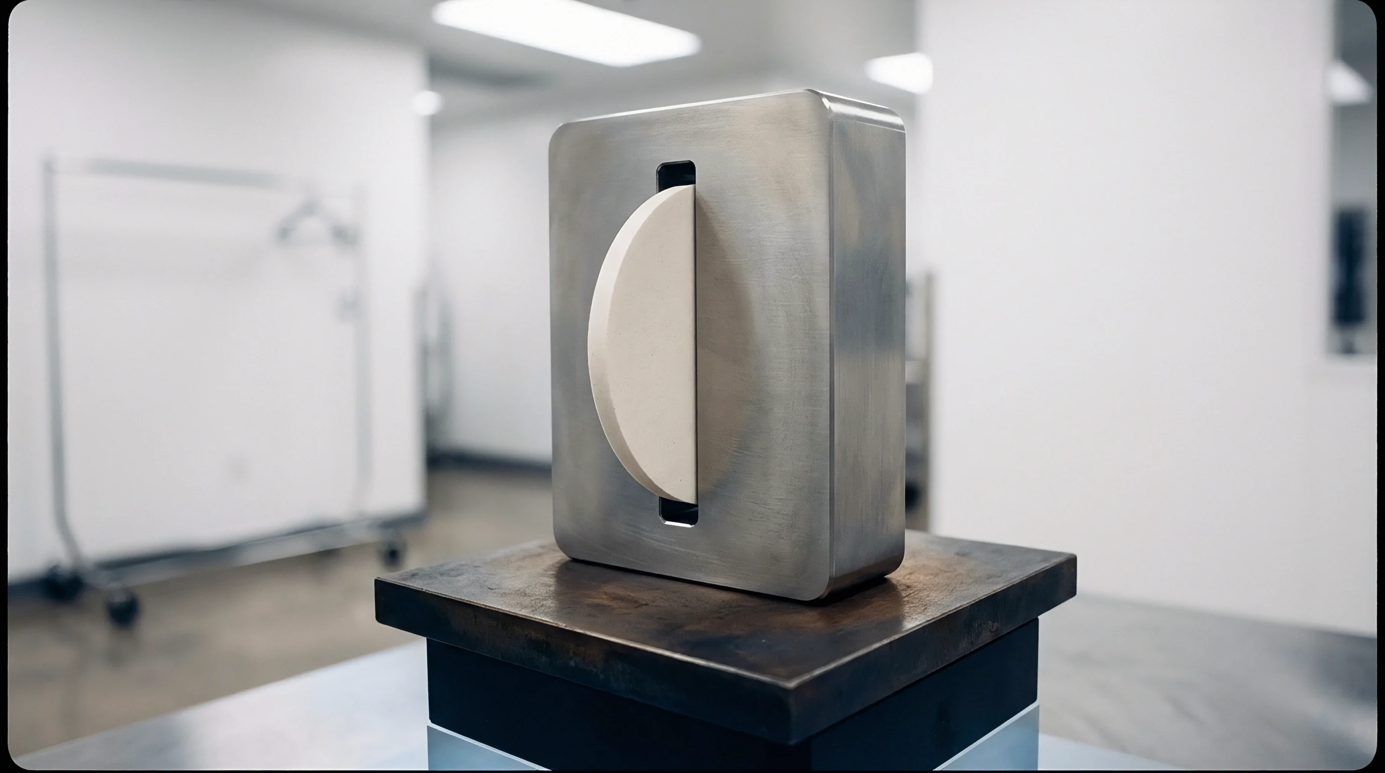
Testing fixtures replicate module spatial boundaries to gather realistic degradation metrics. Single-cell testing on open benches yields overly optimistic cycle-life data that misses pack-level behavior under rigid containment, making parallel platens and load-sensor tracking essential.
In-Situ Dilatometry and Load Frame Calibration
Precise displacement tracking requires laser sensors decoupled from thermal frame expansion. Thermal expansion of steel load frames during temperature-chamber cycling introduces measurement errors up to fifteen micrometers, masking actual electrode breathing dynamics. Fixture calibration protocols mandate empty-cell thermal baseline runs across the full test temperature spectrum from minus twenty to sixty degrees Celsius.

Impedance Spectroscopy under Dynamic Mechanical Load
High-frequency resistance measurements distinguish ohmic electrolyte changes from charge-transfer resistance shifts. Integrating electrochemical impedance spectroscopy into dynamic load frames permits real-time tracking of interphase degradation. As stack pressure rises, the high-frequency intercept remains steady until separator pore collapse alters bulk electrolyte path resistance.
Mid-frequency semicircles expand rapidly under high stress, marking plastic flow within organic interphase components and reduced ion mobility across the passive film.
- Load Sensor Accuracy Strain gauges require active thermal compensation across the entire operational testing temperature range.
- Platen Parallelism Test fixtures demand surface alignment within ten micrometers to prevent localized edge compression spikes.
- Environmental Control Environmental chambers hold ambient temperature within zero point five degrees to isolate thermal expansion from electrochemical expansion.
- Data Logging Frequency Sampling rates for force and displacement channels match the electrochemical data acquisition interval during fast charging.
IEC 62660-2 Section 6.2 mandates external pressure logging during thermal abuse testing, which shifts compliance sign-off liability to the pack integrator when unmonitored compression triggers early vent events.


Seam
Commercial interfaces between cell suppliers and pack integrators hinge on who carries financial liability for stack pressure growth over five years of field operation. Cell warranties frequently specify tight pressure boundaries, compelling pack designers to establish pad stiffness early to avoid costly pre-production tooling modifications.

Ownership Boundaries and Tooling Amortization for Module Endplates
Aluminum endplate casting tooling costs scale rapidly when structural load ratings exceed twenty kilonewtons per cell stack. When cell thickness tolerances drift by even fifty micrometers per cell across a twenty-cell module stack, total stack baseline thickness varies by one millimeter. If the pack integrator uses rigid cast endplates without adaptive foam buffering, this manufacturing tolerance stack-up alters initial stack pressure by up to two megapascals, shifting early cell degradation liabilities back and forth across contract boundaries.

BMS Integration of Pressure-Dependent Charge Protocols
Software algorithms dynamically adjust maximum charging current using strain gauge inputs from module compression rods, as warranty coverage often hinges on these pressure logs.
| Format Type | Internal Strain Management | Pack Integration Containment | Compliance Owner |
|---|---|---|---|
| Cylindrical 21700 / 4680 | Wound jellyroll radial stress absorbed by steel casing | Thermal interface material shear strain management | Cell Manufacturer (Internal Casing) |
| Prismatic Hard Case | Internal core breathing accommodated by side wall flex | Module endplate containment prevents web bulging | Shared Seam (Pack house manages stack pressure) |
| Pouch Large Format | Zero internal containment; flexible pouch expands freely | Full structural module frames and elastic compression pads | Pack Integrator (Full responsibility for stack pressure) |
Fixing module compression pad stiffness early in design prevents costly mid-tooling die modifications when cell thickness tolerances drift.
Negotiating clear stack pressure allowances within cell purchase specifications protects pack integrators from absorbing early wear costs caused by unannounced chemistry or electrode density modifications.