Microstructural Carbide Distribution in Electrode Tooling
Uniform submicron carbide distribution in PM steels and tungsten carbide tooling prevents edge pull-out, holding electrode foil burrs under seven micrometers.

Phase
Scanning electron micrographs of a worn rotary slitting blade edge operating on 15-micrometer double-side coated nickel-manganese-cobalt cathode foil reveal localized cratering centered on hard inclusion clusters. In conventional ingot-cast D2 tool steel, primary chromium carbides frequently coalesce into elongated stringers measuring between 12 and 25 micrometers in major diameter along the hot-rolling axis. When these coarse microstructural hard constituents encounter abrasive transition metal oxide slurry particles under high line speeds, the surrounding martensitic steel matrix yields under cyclic shear loading.
The unsupported hard particles break free from the metallic matrix, leaving microscopic pits along the cutting crest. Microstructural dispersion determines whether a slitting blade or punch die wears through uniform abrasive erosion or suffers accelerated edge collapse.
Powder metallurgy processing transforms this structural dynamic. Gas atomization of molten tool steel rapidly freezes liquid droplets into homogeneous spherical powders, suppressing macro-segregation before hot isostatic pressing consolidates the solid. In PM steel grades like CPM 10V or Vanadis 4 Extra, vanadium combines with carbon to precipitate fine, spherical vanadium carbides measuring under 2 micrometers, uniformly distributed throughout a tempered martensitic matrix.
The absence of primary carbide networks eliminates directional weakness, ensuring equal wear resistance across longitudinal and transverse cutting directions.

Primary Carbide Morphologies in High-Alloy Tool Steels
Alloy metallurgy dictates the chemical identity, hardness, and spatial arrangement of hard precipitate phases in electrode manufacturing equipment. High-chromium cold-work steels rely on M7C3 type chromium carbides with microhardness values between 1,200 HV and 1,600 HV. High-speed steels containing tungsten, molybdenum, and vanadium form M6C and MC type carbides, where MC vanadium carbides reach hardness levels from 2,400 HV to 3,000 HV, exceeding the abrasive hardness of lithium nickel-manganese-cobalt oxide slurry particles (typically 800 HV to 1,100 HV).
Submicron tungsten carbide grades bound by 6 to 12 percent cobalt display ultrafine grain sizes ranging from 0.2 to 0.6 micrometers. The reduced mean free path between tungsten carbide grains in ultrafine structures prevents localized matrix erosion. Submicron tungsten carbide maintains razor sharpness across extended slitting cycles, provided mechanical shock and bending stresses remain within structural limits.
Primary vanadium carbide clusters exceeding twelve micrometers in ingot-cast tool steel accelerate localized edge chipping by four hundred percent compared to submicron powder metallurgy distributions under continuous nickel-manganese-cobalt cathode slitting.
| Tool Material Grade | Carbide Type & Volume Fraction (%) | Max Carbide Grain Size (µm) | Matrix Hardness (HRC / HV) | Edge Life (Linear Meters) |
|---|---|---|---|---|
| Ingot-Cast AISI D2 | M7C3 Chromium (13%) | 22.0 | 60 – 62 HRC | 45,000 |
| PM CPM 10V | MC Vanadium (17.5%) | 2.5 | 62 – 64 HRC | 350,000 |
| PM Vanadis 8 | MC Vanadium (15%) + M7C3 (5%) | 1.8 | 63 – 65 HRC | 480,000 |
| Submicron WC-6Co | WC Tungsten (94%) | 0.4 | 1,650 – 1,800 HV | 1,800,000 |
Matrix Retention Mechanics during Cathode Foil Shearing
Slurry coated current collectors present a compound wear profile. Aluminum collector foils of 10 to 15 micrometer thickness require precise shearing forces, while the overlaying cathode coating containing polyvinylidene fluoride binder and active oxide powder acts as an abrasive lap. Under shearing contact, softer steel matrix zones between large primary carbide stringers wear down rapidly, leaving the hard particles standing in relief.
Mechanical leverage from incoming slurry particles snaps these exposed precipitates at their root.
Fine microstructures prevent relief formation. When the inter-carbide spacing drops below 1 micrometer, active material particles slide across a smooth composite face, distributing contact forces across millions of micro-contacts per square millimeter. The supporting steel matrix remains shielded from direct slurry abrasion.
Matrix hardness must remain above 62 HRC to prevent elastic bending around individual carbide grains under continuous contact pressure.
When blade edge deterioration surfaces during production runs, tooling fabricators frequently claim that raw material suppliers delivered certified PM tool steel stock within nominal chemical specifications. That explanation ignores how post-atomization forging ratios and thermal processing modify final microstructural band spacing.
Shear
Mechanical stress during electrode cutting concentrated over a razor-thin contact zone induces simultaneous mechanical, thermal, and tribological degradation. Active slurry coatings exhibit extreme abrasiveness under high-velocity rotary slitting. Slit edges must remain free from micro-cracks, coating delamination, and particulate debris to preserve cell assembly yields and long-term electrochemical safety.
Shear force distributions across current collector foils depend on edge sharpness, punch clearance, and material yield strength. Double-sided coated electrodes introduce asymmetric stresses; the brittle ceramic cathode layer fractures instantly upon blade contact, while the ductile metallic foil underneath undergoes plastic elongation before complete separation. Microstructural carbide uniformity governs how cleanly the cutting edge initiates this crack network through the electrode layers.
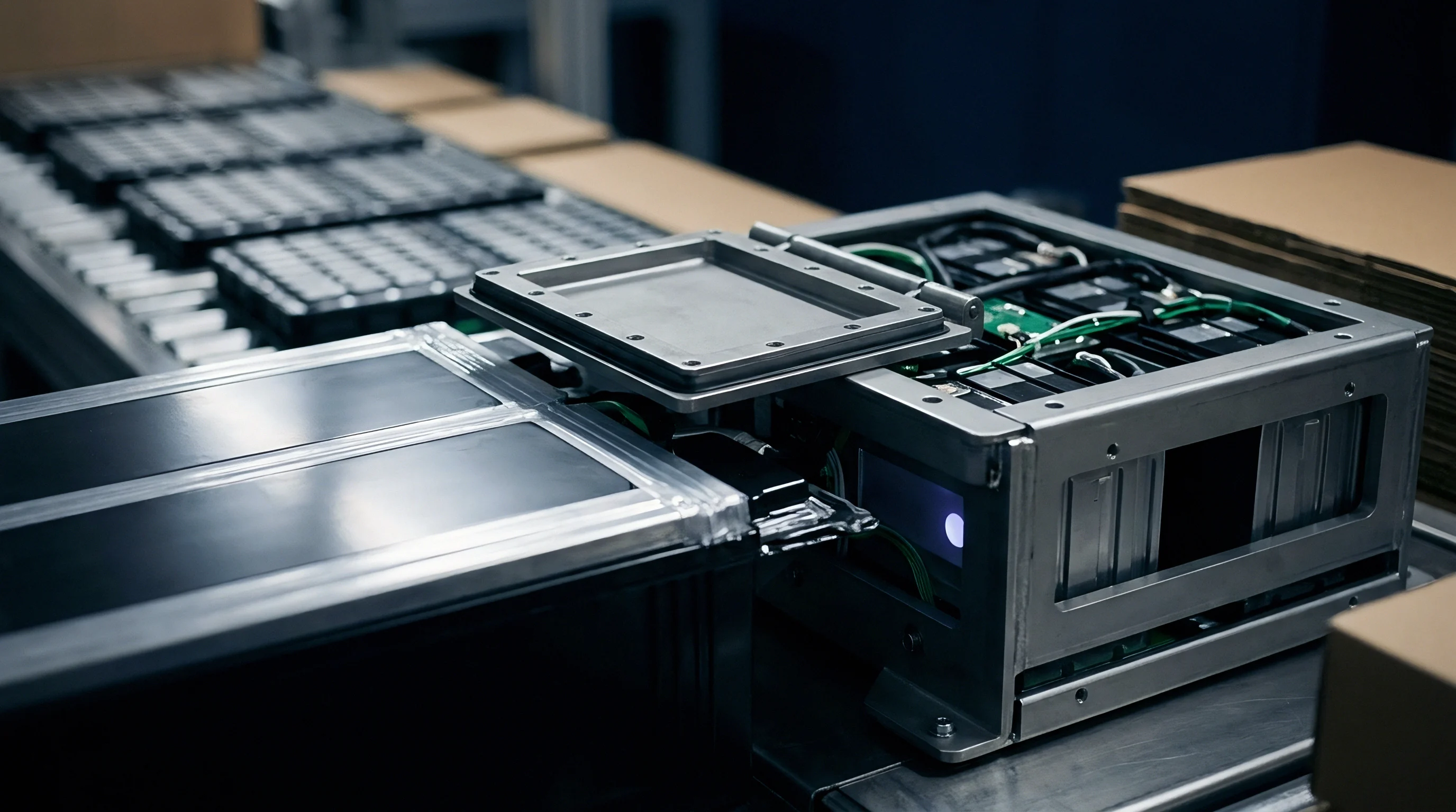
Abrasive Mechanics of Lithium Transition Metal Oxides
Ceramic particles embedded in cathode coatings exert continuous micro-plowing action against the blade surface. High-nickel chemistries such as NCM 811 contain hard crystalline aggregates that strip steel binder from punch faces. Repeated impact against active material aggregates generates high flash temperatures at the cutting tip, reaching estimated peak temperatures above 400 degrees Celsius inside localized contact points.
Thermal spikes lower the hardness of non-optimized steel matrices. High-alloy PM tool steels containing cobalt and tungsten resist thermal softening through secondary hardening precipitate phases that remain stable up to 550 degrees Celsius. In contrast, standard cold-work steels suffer localized tempering, accelerating matrix creep and subsequent carbide loss.
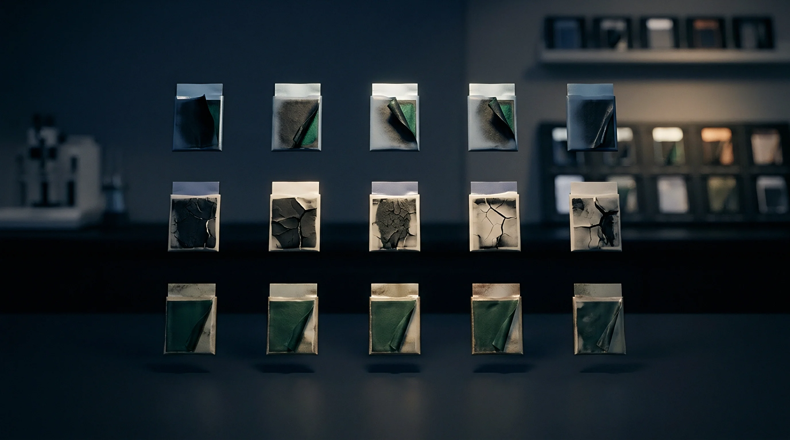
Carbide Pull-Out Verses Micro-Chipping Failure Modes
Degradation modes split into two physical paths based on internal grain structures. Coarse carbide networks initiate micro-chipping when cyclic mechanical loading causes fatigue cracks to propagate along brittle carbide-matrix interfaces. A single micro-chip creates a localized breach in the blade profile, causing instantaneous burr spikes on the cut foil.
Submicron microstructures fail through gradual adhesive and abrasive wear. Carbide pull-out occurs only at an atomic scale, resulting in uniform edge recession without sudden chipping events. Blade degradation follows a linear path, permitting predictable maintenance intervals and preventing catastrophic foil tearing on automated winding lines.
Quantified field measurements establish that a PM 10V rotary slitting blade set operating on 15-micrometer double-side coated NCM 811 electrode foil delivers an average service life of 350,000 linear meters before requiring resharpening. This baseline assumes continuous operation at 80 meters per minute line speed, 12 percent slurry binder content, and a tight punch-to-die clear gap of 5 percent foil thickness. If slurry agglomerate sizes exceed 5 micrometers due to dispersion defects in slurry mixing, or if clearance opens to 10 percent, edge life drops by up to 40 percent.
- Carbide Pull-Out Voiding initiates when local contact stress exceeds matrix yield strength, plucking hard primary precipitates from the tool surface and creating micro-cavities that collect slurry debris.
- Intergranular Chipping develops along continuous primary carbide networks, propagating micro-cracks along grain boundaries until gross fragments detach from the cutting crest.
- Matrix Thermal Softening arises under localized friction spikes, lowering matrix yield strength and permitting embedded hard grains to tilt under cutting pressure.
- Adhesive Foil Transfer occurs when aluminum or copper metal welds to exposed soft steel matrix zones, increasing friction and tearing current collector foils during stroke retractions.
Ignoring microstructural carbide distribution when selecting electrode slitting dies leads to severe burr formation, separator puncture during cell stacking, and premature internal short circuits that ruin entire battery module lots during formation testing.
Burr
Protrusion height along slit current collector edges represents the critical quality parameter in battery electrode preparation. Excessive metallic burrs protruding past the coating profile act as physical spikes that pierce thin polyolefin separator membranes during cell winding or pouch stacking. Separator puncture causes micro-short circuits, accelerated self-discharge rates, and elevated thermal runaway risk during battery life cycles.
Shear gap clearance directly controls edge deformation behavior. Clearances set between 3 percent and 7 percent of current collector foil thickness yield clean shear faces with minimal burr extension. As cutting edges wear and round off due to carbide pull-out, effective shear clearance opens up, converting pure shearing action into tensile bending and plastic tearing.
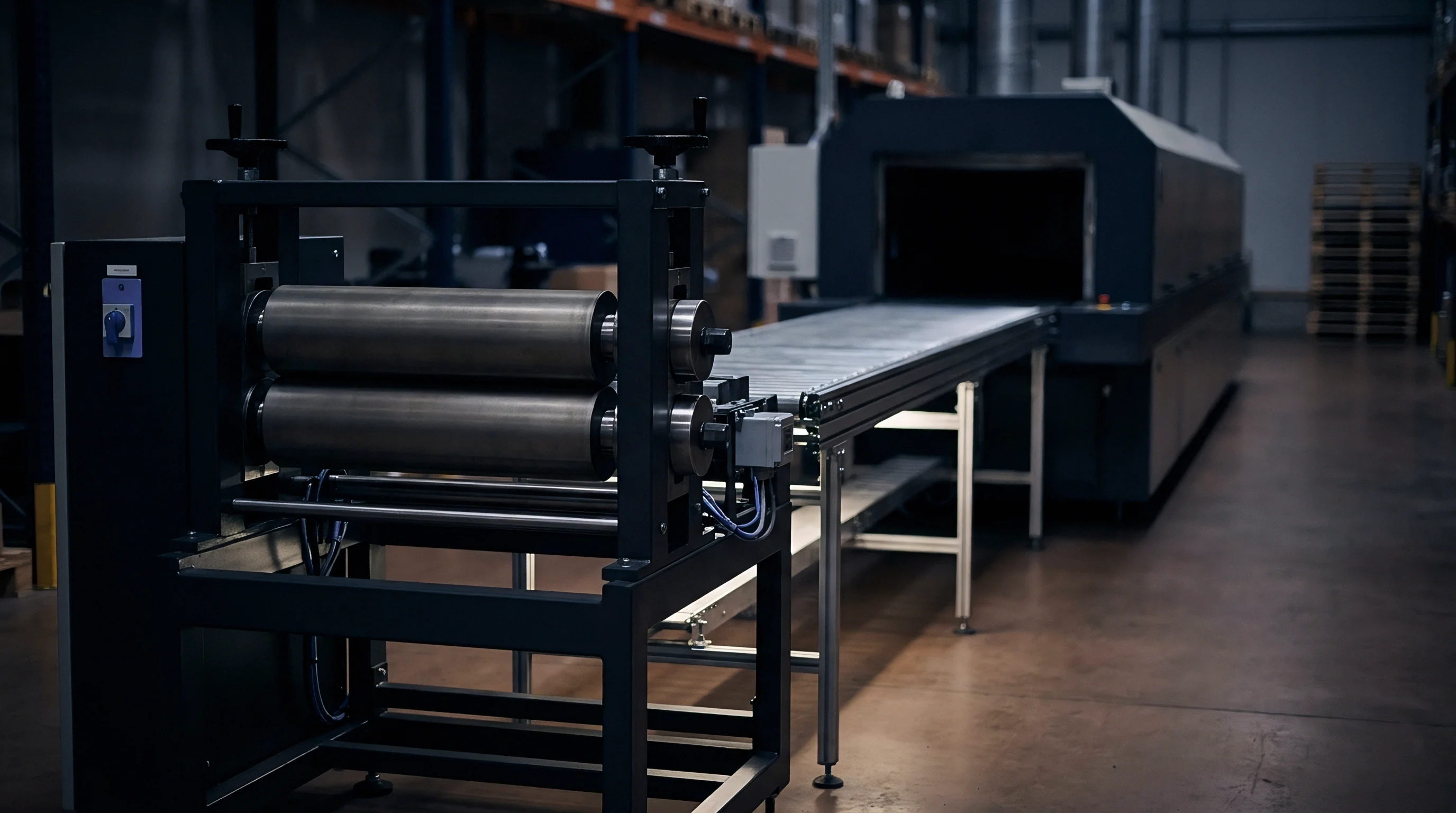
Foil Edge Deformation and Clearance Dynamics
Aluminum current collectors deform differently than copper substrates during blanking operations. Ductile copper foils require tight tool clearance and sharp cutting edges to achieve complete fracture before excessive plastic drawing occurs. Aluminum foils, though softer, form thin stringer burrs when blade radii expand past 5 micrometers.
Microstructural carbide size establishes the lower boundary for reachable blade edge radius. Standard grinding operations cannot produce an edge radius smaller than the average carbide grain diameter without dislodging hard particles from the matrix. PM steels with 1-micrometer carbide distributions accept edge radii under 2 micrometers, while submicron tungsten carbide achieves sharp radii down to 0.5 micrometers.
- Verify Punch Alignment using laser micrometer tools to ensure bilateral shear clearance remains symmetric within 0.5 micrometers across the entire blade length.
- Inspect Edge Radius under optical profilometry, flagging any blade section displaying an edge radius exceeding 3 micrometers prior to installing tooling on the line.
- Monitor Burr Heights at twenty-minute intervals during line operation, using automated optical inspection systems calibrated to trigger line stops at 7-micrometer burr thresholds.
- Track Clearance Drift caused by thermal expansion of punch shafts, adjusting tool heating loops to maintain fixed clear-gap ratios throughout extended production shifts.
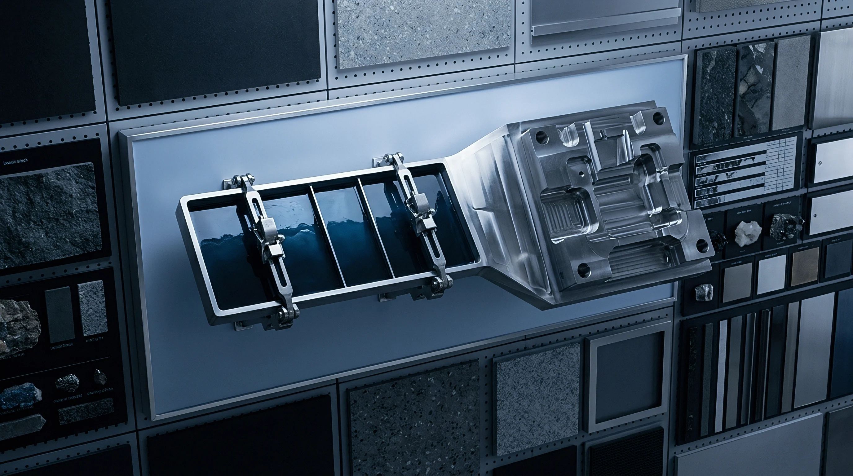
How Does Carbide Size Limit Minimum Burr Height?
Edge sharpening cannot create a geometric profile finer than the underlying material phase distribution. When a grinding wheel passes over a tool steel matrix containing 15-micrometer carbide clusters, the wheel either cuts through the hard carbide or tears it out of the surrounding soft steel matrix. If the carbide tears out, the resulting edge profile contains a micro-notch equal to the size of the removed particle.
Notches along the cutting tip concentrate local stress and allow metallic foil material to flow into the gap during stroke execution. This metal flow leaves a standing burr on the slit electrode edge matching the notch dimensions. Utilizing tool materials with uniform submicron carbide dispersion ensures the blade edge maintains a continuous, smooth contour, holding burr heights consistently under 5 micrometers across hundreds of thousands of punch cycles.
The precise point where localized carbide pull-out initiates binder delamination on water-processed iron phosphate cathodes varies between 1.8 and 4.2 micrometers of tool edge recession based on slurry adhesion strength. Field data covering high-speed water-based slurry lines remains inconsistent across binder suppliers; cell buyers enforce strict incoming microstructural certification for all punching die lots rather than relying on vendor tool life estimates.
Compliance with standard SEP 1615 microstructural rating class two or better limits edge protrusion to seven micrometers, eliminating separator puncture risk during pack cell aging.
| Foil Substrate | Punch Clearance (% Foil Thickness) | Initial Burr Height (µm) | Burr Height at 100k Cycles (µm) | Primary Failure Mode |
|---|---|---|---|---|
| 12 µm Aluminum (Cathode) | 4.0% | 1.8 | 4.2 | Uniform Abrasive Wear |
| 12 µm Aluminum (Cathode) | 10.0% | 4.5 | 12.8 | Foil Rollover & Heavy Burr |
| 8 µm Copper (Anode) | 3.5% | 1.2 | 3.8 | Micro-Chipping at Edge |
| 8 µm Copper (Anode) | 8.5% | 3.2 | 10.5 | Plastic Tearing & Stringer Burr |
What fundamental microstructural phase transformations occur at the extreme cutting tip when submicron tungsten carbide punches experience dry, high-speed rotary shearing against silicon-composite anode foils under extended production runs?
Grinding
Restoring worn electrode tooling demands rigorous microstructural management during re-sharpening operations. Conventional tool re-grinding focused solely on dimensional recovery often leaves damaged sub-surface layers containing thermal micro-cracks, tensile residual stresses, and transformed retained austenite. High-precision electrode slitting tools require specialized grinding profiles to remove damaged material without introducing thermal shock.
Coolant delivery during resharpening determines sub-surface structural integrity. Inadequate coolant flow allows local friction temperatures to rise past the re-austenitizing temperature of tool steel, followed by rapid quenching from bulk cold metal behind the contact zone. This thermal cycle forms brittle, untempered martensite (white layer) along the freshly ground edge, guaranteeing catastrophic micro-chipping within the first thousand slitting strokes after tool re-installation.
Resharpening Depth and Thermal Damage Removal
Determining the correct depth of cut per pass prevents heat buildup while ensuring complete removal of work-hardened material. A single aggressive grinding pass causes thermal expansion differential between hard carbides and the surrounding matrix, creating micro-fissures that extend several micrometers below the visible surface. Re-sharpening protocol requires shallow depth passes combined with high wheel speed and synthetic oil coolant saturated with extreme pressure additives.
Every re-sharpening cycle must penetrate past the fatigue zone created during the tool’s preceding production run. Inspecting ground edges with eddy-current probes or chemical etching verifies complete removal of work-hardened matrix layers. Failure to grind past the fatigue depth causes rapid re-emergence of edge micro-chipping.
Diamond Lapping Parameters for Edge Radius Restoration
Lapping serves as the final surface conditioning step for electrode cutters, converting ground finish topographies into mirror surfaces with roughness values under Ra 0.05 micrometers. Vitrified or resin-bonded diamond wheels with particle sizes between 1 and 3 micrometers polish away grinding ridges while controlling edge rounding.
Polishing directional parameters must run parallel to the cutting edge trajectory. Cross-grain lapping leaves perpendicular micro-scratches that act as crack initiation sites under cyclic shear loading. Automated lapping tables utilizing diamond slurry suspensions restore cutting radii to under 1.5 micrometers while preserving carbide particle stability in the matrix face.
- Mount blade on precision magnetic chuck and check total indicator reading runout to confirm mounting variance stays under one micrometer.
- Rough grind edge using resin-bonded cubic boron nitride wheel with oil coolant to remove degraded material to a radial depth of twenty-five micrometers.
- Finish grind using fine resinoid diamond wheel at reduced feed rate to eliminate thermal micro-cracks and bring surface roughness below Ra point-one micrometers.
- Lap blade crest on automated polishing table using one-micrometer diamond compound until optical profilometry confirms edge radius falls below two micrometers.
- Clean finished tool in ultrasonic solvent bath to remove abrasive diamond debris and perform forty-point optical edge inspection.
Coolant velocity during diamond wheel resharpening governs sub-surface thermal stress more directly than wheel feed rate.
Regrinding tool steel blades past the depth of primary carbide distribution uniform bands guarantees rapid edge breakdown during subsequent production runs.
Amortization
Selecting electrode tool materials requires balancing initial capital expenditure against total delivered linear meters of quality electrode foil. High-grade PM tool steels and binderless tungsten carbide carry significant upfront price premiums over traditional ingot-cast steels. Commercial justification rests on extended regrind intervals, reduced line downtime, and lower scrap rates from burr-related cell rejections.
Tooling amortization calculations must incorporate both original tool cost and the complete cycle of resharpening operations over the component’s operational lifespan. A tool grade that costs four times more initially but delivers eight times the wear life while surviving double the regrind count drastically reduces landed electrode cost per kilowatt-hour of produced battery capacity.
Capital Expenditure Comparison across Tool Material Grades
Standard AISI D2 steel slitting blades offer low initial NRE costs, making them appealing for pilot lines or short-run prototype manufacturing. However, high wear rates require blade replacement or regrinding every 45,000 meters under cathode slitting conditions. Continuous mass-production lines operating at 100 meters per minute consume standard steel blades rapidly, creating massive labor overhead and lost line takt time during blade changeovers.
PM tool steels such as CPM 10V or Vanadis 8 elevate initial purchase costs by 200 to 300 percent while extending stroke capacity by 600 to 800 percent between resharpening cycles. Ultrafine tungsten carbide further extends run capacity, reaching over 1.8 million linear meters per sharpen under optimal alignment conditions. The amortized tooling expense per 100,000 meters drops steadily as material grade performance rises, despite higher initial NRE outlay.
Calculating the true landed amortization for submicron WC-Co tooling yields a baseline cost of $34.20 per 100,000 linear meters of slit electrode foil. This figure rests on achieving six regrind cycles per blade set, maintaining a standardized 0.5 millimeter removal depth per resharpen, and experiencing zero catastrophic edge chipping events. Should unexpected matrix cracking or operator drop handling damage reduce regrind frequency to two cycles, amortized cost jumps to $78.50 per 100,000 meters.
Tool steel specification boundaries dictate total electrode manufacturing yield far more than raw material alloy costs.
| Material Category | Initial Blade Set Cost (USD) | Max Regrind Cycles | Total Life Capacity (Linear Meters) | Amortized Cost / 100k Meters (USD) |
|---|---|---|---|---|
| Ingot Steel (AISI D2) | $600 | 3 | 180,000 | $333.30 |
| PM Steel (CPM 10V) | $1,800 | 5 | 2,100,000 | $85.70 |
| PM Steel (Vanadis 8) | $2,200 | 6 | 3,360,000 | $65.40 |
| Submicron WC-6Co | $5,500 | 8 | 16,200,000 | $33.95 |
Quality Acceptance Standards in Tooling Procurement Contracts
Procurement agreements for battery electrode cutting dies must contain explicit metallurgical qualification metrics rather than simple hardness and dimensional certificates. Microstructural acceptance criteria state allowable carbide rating numbers defined by ISO 4499 or ASTM A600 standards, capping maximum primary carbide sizes and banning carbide network banding entirely.
Contractual guarantees must define minimum regrind survival counts and maximum burr height thresholds over guaranteed linear meter baselines. Incorporating mandatory first-article optical profilometry scans and microstructural band verification upon tooling receipt protects pack integrators from absorbing premature tooling failures caused by poor heat treatment or improper steel atomization at the foundry level.
A standard quality clause in a tooling master services agreement states that any delivery lot containing primary carbide stringers exceeding 5 micrometers under ISO 4499 microstructural classification, or displaying matrix retained austenite above 3 volume percent, entitles the buyer to immediate lot rejection and full supplier reimbursement of line downtime costs.