Evaluating Interfacial Foam Compression Set Effects on Module Stress Distribution Profiles
Foam compression set collapses baseline clamping force, shifting planar pressure to rigid edges, elevating thermal impedance, and risking tab fatigue.


Foam
Elastomeric cushions placed between pouch or prismatic cells absorb dimensional shifts driven by electrochemical reactions during operation. These physical layers modulate external loads across the face of the active materials, maintaining internal contact pressure without exceeding structural thresholds. When a polymer sheet loses its ability to return to its original thickness following prolonged strain, interfacial contact forces collapse.
This permanent strain, known as compression set, alters the physical geometry of the cell stack inside a rigid module frame.
Selecting the proper foam formulation determines whether the module survives long-term operation.
Interfacial pads perform dual duties inside high-density modules. They provide necessary compliance to accommodate anode volume expansion during lithiation, while simultaneously maintaining a minimum baseline clamping pressure during delithiation. Standard lithium-ion chemistries, particularly silicon-graphite composite anodes and high-nickel layered oxides, exhibit continuous volume changes throughout every charge and discharge sequence.
Without a compliant interlayer, these dimensional shifts generate localized stress peaks capable of crushing internal separators, fracturing current collector tabs, or deforming module end-plates.

Mechanics of Microcellular Polymeric Interlayer Deflection
Cell breathing during charge and discharge cycles induces cyclic displacement against boundary constraints. Under initial installation, the interfacial pad sits at a defined pre-load thickness, typically compressed between 20 percent and 30 percent of its free state height. This initial compression establishes a uniform planar force across the cell face.
As the pack operates, temperature fluctuations and concentration gradients force the polymer matrix through millions of micro-scale compression cycles. Microcellular foams distribute this strain through the bending and buckling of open or closed cell walls within the elastomer backbone.
Closed-cell silicone elastomers and microcellular polyurethanes react differently to sustained mechanical displacement. Polyurethane formulations rely on hard and soft phase separation within their molecular chains, where hydrogen bonding provides elastic recovery. Silicone elastomers depend on flexible siloxane bonds with cross-linked polymer networks that resist thermal degradation across wider operating windows.
Under continuous compressive stress at elevated pack temperatures, polymer chains in both material families undergo irreversible microstructural rearrangement. This molecular slippage converts elastic potential energy into permanent physical deformation, reducing the uncompressed recovery height of the pad.
Irreversible microstructural rearrangement causes polymer chains to slide permanently out of alignment.
The loss of uncompressed thickness permanently reduces the baseline mechanical force exerted by the foam when the battery sits at a low state of charge. When the cell contracts during discharge, a pad with high compression set fails to expand back to its original interface boundary. This failure creates localized microscopic air gaps or zones of zero contact pressure between the cell casing and adjacent thermal management plates.
Consequently, heat transfer across the interface deteriorates rapidly, escalating thermal gradients inside the active electrode assembly.
A silicone foam exhibiting a 12 percent compression set under ISO 1856 Method A preserves interfacial contact pressure above 15 kilopascals after 3,000 thermal cycles at 45 degrees Celsius.

Cyclic Intercalation Swelling and Permanent Strain Accumulation
Graphite anodes expand up to ten percent at full state of charge due to lithium ion insertion into the crystal lattice. Silicon alloy additions increase this volumetric expansion significantly, driving localized surface strain higher with every percent of added silicon. Over extended calendar aging, solid electrolyte interphase formation continuously consumes cyclable lithium, leaving thick inorganic deposits on anode particle surfaces.
This degradation process generates irreversible thickness growth across the entire cell package, superimposed on top of the reversible cyclic breathing.
Accumulated structural growth causes cell swelling to progress relentlessly across the pack’s life.
The combination of cyclic breathing and irreversible growth subjects the interlayer foam to continuous high-amplitude strain cycles. If an interlayer pad exhibits poor viscoelastic recovery, the peak compressive stress generated at 100 percent state of charge drops progressively over cycle life. While this stress drop reduces maximum load exposure on the module end-plates, it severely degrades the minimum clamping force at zero percent state of charge.
Low baseline pressure allows internal electrode layers to wrinkle or shift during vehicle vibration, initiating mechanical degradation of the separator foil.
| Material Chemistry | Density (kg/m³) | Initial Elastic Modulus (MPa) | Compression Set ASTM D3574 Test D 70°C 22h (%) | Compression Deflection Stress at 30% Strain (kPa) | Thermal Conductivity (W/m·K) |
|---|---|---|---|---|---|
| Microcellular Polyurethane | 240 to 320 | 0.45 to 0.85 | 8.5 to 14.0 | 45 to 80 | 0.07 to 0.11 |
| Cross-Linked Silicone Foam | 350 to 480 | 0.60 to 1.20 | 3.2 to 6.5 | 60 to 110 | 0.12 to 0.22 |
| Closed-Cell EPDM Rubber | 180 to 260 | 0.30 to 0.65 | 18.0 to 28.0 | 30 to 55 | 0.05 to 0.09 |
| Fluorosilicone Elastomer | 400 to 550 | 0.80 to 1.50 | 4.5 to 8.0 | 75 to 135 | 0.15 to 0.25 |
| Compression set values measured per ASTM D3574 Test D under 25 percent constant deflection at specified ambient temperature for 22 consecutive hours following 30-minute recovery at standard room conditions. | |||||
Interfacial degradation propagates through distinct structural and thermal failure pathways when compression set exceeds engineering allowances. The following mechanical failure modes emerge across module life:
- Interfacial pressure collapse occurs when permanent foam height reduction drops minimum contact pressure below twenty kilopascals at low state of charge, inducing active electrode layer buckling.
- Thermal interface separation develops as loss of spring energy creates microscopic void spaces between cell walls and cooling plates, elevating localized thermal resistance.
- Concentrated edge loading forms when non-uniform cell swelling compresses the center of the foam beyond its yield point, shifting total clamping force onto rigid module side frames.
- Interconnect fatigue failure manifests when unconstrained cell pouch movement under vibration induces high-cycle cyclic strain on laser-welded busbar terminals.
- Cascading cell compression overload occurs when rigid end-plates retain initial displacement, transferring unabsorbed volumetric expansion directly into adjacent cell structures during high-temperature fast charging.
Material suppliers frequently argue that elevated initial stiffness compensates for long-term set accumulation. Field tear-down analysis confirms that high initial modulus simply increases early-life mechanical stress on internal busbars without preventing late-life contact loss once viscoelastic relaxation sets in. Relying on initial stiffness to offset permanent set leads to module deformation during early thermal cycling.

Load
Mechanical force distribution across a cell pack determines structural stability and electrical interconnect integrity. As interfacial pads experience compression set, the planar pressure distribution across cell pouch faces undergoes severe distortion. What begins as a uniform compressive pressure profile evolves into a complex spatial stress map dominated by high-stress peaks at rigid boundaries and complete unloading across central regions.
Localized pressure peaks can crush separators and cause premature electrical failure.
Evaluating this stress redistribution requires high-resolution tactile matrix pressure sensors inserted between cell walls and structural cooling frames during environmental cycling. Baseline measurements taken on newly assembled modules show uniform planar pressures, typically centered between 50 and 100 kilopascals. This controlled pressure maintains tight internal layer alignment within jelly-rolls or stacked pouch architectures, limiting lithium dendrite growth by preventing localized gap formation.

Spatial Pressure Distribution Profiles across Prismatic Module Stacks
Planar pressure uniformity degrades over operational lifetimes as structural compliance decays. Cells positioned in the center of a dense prismatic module experience higher localized temperatures due to restricted heat dissipation paths. Elevated temperature accelerates the viscoelastic compression set of the foam pads adjacent to these central cells.
Consequently, central pads lose recovery force faster than end-of-stack pads, causing a localized drop in clamping pressure along the middle of the module axis.
This axial pressure differential forces rigid module side-ties and top covers to bear asymmetric structural loads. End-plates rotate slightly outward under initial pre-load, concentrating compressive forces along the top and bottom edges of peripheral cells. When central foam pads lose elastic recovery due to compression set, the structural end-plates relax inward slightly, further redistributing force concentrations toward the rigid module corners.
Tactile pressure map captures reveal edge-stress concentration factors exceeding three times the nominal average module design stress.
Over extended cycling, uniform clamping pressure across the module face vanishes entirely.
Stress concentration across the perimeter of cell pouch seals accelerates seal degradation. Polypropylene seal layers experience continuous shear forces when internal cell pressure spikes during aggressive charge cycles, leading to electrolyte vapor leakage over extended service lifetimes. Furthermore, uneven planar force distributions induce differential current density profiles across electrode surfaces.
Areas under high localized compression experience reduced inter-particle contact resistance and lower porosity, forcing higher localized current densities that accelerate lithium plating during cold-temperature charging.
Maintaining elastomeric resilience across the operating temperature window prevents structural end-plate deflection from translating into tab solder joint fatigue.

Mechanical Constraint Limits for Active Material Micro-Cracking
Exceeding critical surface stress thresholds causes particle fracture within high-nickel cathode materials. Single-crystal and polycrystalline NMC formulations respond differently to external mechanical pressure fields. Polycrystalline particles contain internal grain boundaries susceptible to micro-cracking when localized compressive stress exceeds approximately 0.5 megapascals under simultaneous electrochemical insertion strain.
Micro-cracks expose fresh active surfaces to continuous electrolyte decomposition reactions, consuming cyclable lithium and generating internal gas.
When foam compression set allows non-uniform stress distribution, localized pressure hot-spots easily cross the critical micro-cracking threshold. Central regions of the cell face may experience complete pressure loss, while perimeter zones bear the entire module pre-load. This concentrated compression crushes secondary particle agglomerates near outer edges, accelerating impedance growth in those specific active regions.
Over time, this non-uniform aging profile limits total module discharge capacity.
- Tactile sensor insertion requires position calibration between cell face center points and boundary edges using thin-film pressure arrays rated for 0 to 2 megapascals.
- Pre-load baseline calibration captures initial planar stress profiles at twenty-five degrees Celsius immediately following final structural enclosure torquing.
- Thermal soak exposure subjects the instrumented module assembly to elevated operational temperatures under defined constant current charge-discharge regimes.
- Dynamic pressure logging records real-time spatial stress shifts at minimum and maximum states of charge across specified cycle intervals.
- Spatial gradient extraction isolates peak-to-average pressure ratios and pinpoints localized stress zones exceeding active material yield thresholds.
Validation testing demonstrates a 34 percent reduction in interfacial pressure across 1,000 thermal cycles. This drop correlates directly with the progression of permanent foam set inside the enclosure. When interfacial pads lose elastic memory, internal cell expansion forces are no longer damped across the full face of the active material, focusing stress onto rigid structural anchor points.
| Aging Interval (Cycles at 45°C) | Peak Pressure Center Zone (kPa) | Minimum Pressure Center Zone (kPa) | Perimeter Edge Stress (kPa) | Peak-to-Average Pressure Ratio | Contact Area Loss (%) |
|---|---|---|---|---|---|
| 0 (Initial Assembly) | 85 | 72 | 90 | 1.11 | 0.0 |
| 500 | 68 | 45 | 115 | 1.45 | 2.8 |
| 1,500 | 42 | 18 | 140 | 2.10 | 8.5 |
| 3,000 | 22 | 2 | 185 | 3.85 | 18.2 |
Designing module mechanical constraints requires balancing early-life pre-load forces against late-life compression set limits. A soft foam pad prevents initial high-stress spikes but reaches total physical displacement capacity early in pack life. A rigid foam pad maintains structural alignment under load but transfers destructive peak forces directly into active material particles during cell swelling.
Matching foam load-deflection curves to cell swelling kinetics ensures stress maps remain within safe operational bounds across the operational life of the pack.
Module structural survival depends on keeping localized stress peaks below active material particle yield points across all operating temperatures.


Creep
Polymeric compression pads experience time-dependent stress reduction under sustained deformation inside rigid module frames. Viscoelastic materials display combined elastic and viscous behaviors, meaning their internal molecular stress decreases exponentially over time when held at constant displacement. This stress relaxation phenomenon directly governs how long an interfacial pad can maintain required clamping forces on pouch and prismatic cell assemblies.
Under sustained mechanical strain, elastomeric interlayers undergo continuous relaxation.
Stress decay kinetics accelerate rapidly when modules operate at elevated ambient temperatures. The rate of relaxation follows time-temperature superposition principles, where exposure to sixty degrees Celsius for several hundred hours induces equivalent stress loss to thousands of hours at room temperature. Arrhenius shift factors model this temperature dependence, enabling acceleration factors for qualification testing.
Understanding viscoelastic creep requires separating immediate elastic recovery from permanent molecular chain alteration.

Viscoelastic Stress Relaxation Kinetics under Thermal Load
Elevated temperature accelerates internal polymer chain restructuring under constant displacement. When a module is bolted together, interfacial pads undergo immediate elastic strain. Over hours and days, secondary cross-links within the polymer matrix break and reform in relaxed configurations, dissipating stored strain energy.
The Kohlrausch-Williams-Watts stretched exponential model describes this decay curve accurately, accounting for heterogeneous relaxation times across complex polymer networks.
As stress decays, the physical force exerted by the foam against adjacent cell faces drops proportionally. In a closed module, cell swelling increases displacement on the pad, temporarily driving stress up. However, the higher stress level accelerates the rate of relaxation, eroding the mechanical baseline faster.
Under continuous high-temperature storage or aggressive vehicle driving profiles, the relaxed baseline force drops near zero when cells return to fully discharged, cold conditions.
Sustained heat spikes accelerate polymer degradation throughout the foam matrix.
This total force depletion alters the mechanical boundary conditions of the cell stack. Cells are no longer firmly clamped within their designated compartments, allowing internal physical movement under external acceleration or vibration. Micro-motion between cell pouches and thermal interface materials causes physical wear on protective PET insulation films, eventually exposing live aluminum cell enclosures to grounded frame structures.
Modules subjected to thermal shock cycling per IEC 62660-2 forfeit structural integrity warranties if foam permanent set exceeds 18 percent.

What Drives Thermal Interface Impedance Spikes under Creep?
Interfacial gap opening occurs when residual spring force drops below the surface roughness threshold of adjacent aluminum cell cans. Thermal interface materials, such as silicone gap fillers or phase-change pads, depend on constant compressive pressure to fill microscopic air voids between mating surfaces. Standard gap fillers require a minimum continuous interface pressure of approximately twenty to thirty kilopascals to maintain optimum thermal contact resistance across operating temperatures.
When viscoelastic creep reduces foam recovery force below this threshold, microscopic gaps open along the heat transfer pathway. Air possesses a thermal conductivity of roughly 0.026 watts per meter-kelvin, which is orders of magnitude lower than typical thermal gap fillers operating between 1.5 and 4.0 watts per meter-kelvin. Microscopic air gaps introduce extreme thermal impedance spikes, restricting heat flow from cell interiors to liquid cooling cold-plates.
As microscopic air gaps form along the interface, contact resistance increases rapidly.
Elevated thermal resistance increases operating cell temperatures during high-rate discharge sequences. Higher cell temperatures further accelerate viscoelastic relaxation in adjacent foam pads, establishing a destructive thermal-mechanical feedback loop. Localized cell hot-spots trigger uneven current distribution, accelerating degradation and driving capacity loss faster than thermal models predict.
- Temperature limit definition sets maximum allowable continuous foam exposure limits based on lifetime viscoelastic stress relaxation models.
- Minimum load margin verification calculates worst-case baseline contact forces at zero percent state of charge under lowest sub-zero operating temperatures.
- Chemical compatibility screening evaluates volatile siloxane or plasticizer outgassing from foam pads under combined high heat and mechanical load.
- Thickness tolerance stacking limits module structural height variation to prevent over-compression during initial assembly operations.
- Dynamic strain allowance matches foam deflection capacity to total projected cell swelling across three thousand full charge-discharge cycles.
Significant variance exists between simple static stress relaxation data provided on supplier datasheets and actual performance measured inside functional module assemblies. Standard datasheet testing holds foam at constant thickness between flat metal plates at room temperature. In contrast, operating modules subject pads to dynamic continuous thickness fluctuations driven by state-of-charge cycling, superimposed on top of elevated thermal conditions.
Static test data consistently underestimates true operational stress relaxation by twenty to forty percent.
Whether dynamic thermal-mechanical cycling alters the fundamental activation energy of polymer chain degradation remains open to investigation within reliability laboratories. Mechanical excitation during physical displacement may create localized micro-tears in foam cell walls, accelerating gas diffusion and permanent physical collapse beyond predictions based strictly on static thermal aging models.


Fixture
Accurate physical measurement of long-term elastomeric compression set demands specialized test hardware designed for environmental and mechanical isolation. Evaluating foam behavior requires precision bench instrumentation capable of separating true polymer deflection from mechanical compliance inside test fixtures and sensor drift. Standard quality control instruments frequently produce misleading results if machine deflection factors are omitted from strain calculations.
Comprehensive dynamic testing reveals the actual mechanical behavior of foam under load.
Qualification test procedures must recreate the multi-axial strain environment experienced inside operational battery packs. Standard test protocols such as ASTM D3574 Test D or ISO 1856 provide baseline material comparison screening, but fail to replicate dynamic cell swelling dynamics. Specialized bench rigs combine high-precision electromechanical actuators, environmental chambers, and continuous tactile load monitoring to evaluate performance under dynamic conditions.

Bench Calibration Metrology for Dynamic Compression Set Characterization
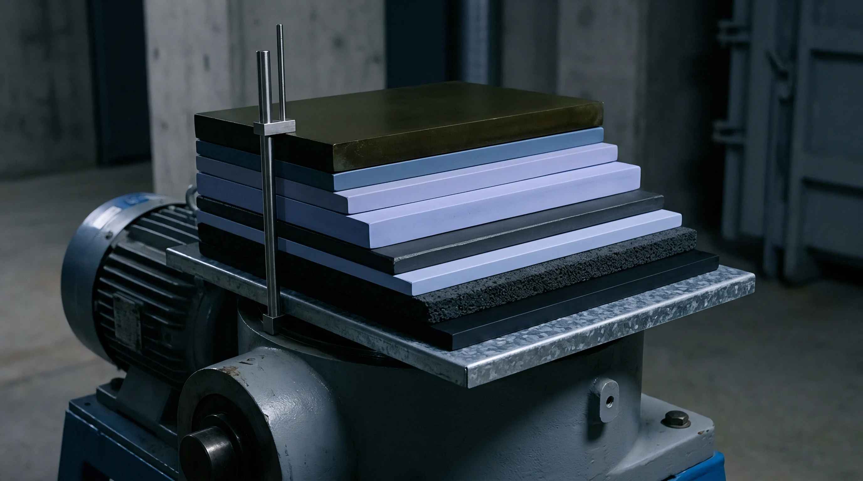
Testing laboratories employ closed-loop hydraulic or electromechanical frames capable of maintaining precise temperature profiles alongside dynamic displacement patterns. Test fixtures incorporate low-expansion invar alloy compression plates to eliminate thermal expansion artifacts during wide-temperature sweeps. Load cells mounted inside the force chain must maintain calibration accuracy across long-term environmental exposure without drifting under sustained static loads.
Precision load cells capture the gradual decay of interfacial force over extended testing cycles.
Compliance calibration represents a mandatory step before gathering compression set data. Every load frame, load cell, and mounting plate deflects slightly under applied force. If a test rig deflects by twenty micrometers under a two-kilonewton load, that deflection is recorded as foam deformation unless compensated by software algorithms.
Technicians determine machine compliance by driving compression plates together without a sample, mapping load-versus-displacement curves across the entire testing force range.
Precise temperature control across compression plates prevents local thermal gradients that alter polymer relaxation kinetics. Heated plates equipped with internal multi-zone heating elements and distributed thermocouples ensure thermal uniformity within plus or minus 0.5 degrees Celsius across the entire foam test sample area. Uncontrolled thermal gradients cause localized variations in compression set rates, obscuring true material degradation behavior.
Cell swelling forces act as a continuous mechanical pump that accelerates structural degradation inside unvented module enclosures.
Structural Integrity Verification under UN 38.3 Mechanical Shock Sequences
Pack qualification testing subjects completed assemblies to eighteen discrete deceleration events across three orthogonal axes. UN 38.3 Test 4 applies severe impact shock profiles, reaching peak accelerations of 150g for small cells or 50g for large module assemblies. When foam pads inside a module have experienced severe compression set, internal mechanical clearances open up, transforming a rigid structural stack into a loose assembly of heavy components.
Unconstrained loose cells risk structural damage and fail transport compliance criteria.
During mechanical shock acceleration vectors, loose cells move within their compartment boundaries before striking adjacent structural ribs or cooling plates. This movement converts impact energy into violent point-load force spikes that easily crush aluminum pouch seal borders or rupture thin cooling plate channels. Modules passing UN 38.3 mechanical shock in their fresh, initial pre-loaded state frequently experience catastrophic failure when subjected to identical shock inputs following accelerated thermal aging and compression set accumulation.
Furthermore, UN 38.3 Test 3 random vibration testing exposes relaxed modules to fretting corrosion hazards. Microscopic relative sliding between unconstrained cell faces and adjacent foam or frame surfaces strips away protective surface anodization, generating conductive aluminum debris inside the pack. Conductive dust accumulation creates low-resistance ground faults, triggering safety isolation faults across high-voltage battery management systems.
| Test Protocol | Primary Standard | Temperature / Environmental Condition | Applied Mechanical Strain / Load | Measured Performance Parameter | Module Design Output Limit |
|---|---|---|---|---|---|
| Static Compression Set | ASTM D3574 Test D / ISO 1856 | 70°C, dry air, 22 hours soak time | Constant 25% height deflection | Permanent unrecovered thickness loss (%) | Maximum allowable set threshold ≤ 10% |
| Dynamic Mechanical Analysis (DMA) | ASTM E1640 | -40°C to 85°C sweep at 2°C/min | Cyclic sinusoidal strain 0.1% amplitude | Glass transition temperature and complex modulus | Storage modulus transition point ≤ -35°C |
| Accelerated Viscoelastic Relaxation | ISO 3384 Method A | 60°C continuous, 1,000 hours duration | Constant compression to original thickness | Residual force retention factor over time | Minimum residual force retention ≥ 40% |
| Dynamic Cell Swelling Simulation | Internal Module Spec | 45°C with 10% to 90% RH control | 0.05 Hz cyclic strain matching cell SOC profile | Peak force decay and interfacial contact area loss | Planar force loss gradient ≤ 25% over 2k cycles |
Standard qualification protocols must be executed in precise sequence to capture accurate degradation metrics. Technicians execute dynamic compression set verification through the following operational steps:
- Mount foam test specimens between calibrated invar compression plates within the environmental chamber enclosure.
- Apply initial baseline compression strain equal to exact module assembly pre-load specifications at twenty-five degrees Celsius.
- Heat test chamber to maximum module operating specification temperature while logging initial elastic force response.
- Initiate low-frequency cyclic displacement profiles matching projected cell thickness growth profiles over target life cycles.
- Record real-time force decay continuously using compliance-corrected load cell data channels.
- Cool test chamber to ambient conditions and release mechanical strain following specified thermal soak duration.
- Measure uncompressed recovery height precisely thirty minutes following force release to calculate final compression set percentages.
Procurement agreements incorporate explicit material specification language to establish legally enforceable quality standards. Procurement contracts specify: “Interfacial cushion pads delivered under this specification shall exhibit a permanent compression set not exceeding 8.0 percent when tested in accordance with ISO 1856 Method A at 70 degrees Celsius for 22 hours. Compliance verification shall occur on raw material batches prior to module lamination, with test summaries attached to shipping documentation.” This clause prevents suppliers from shipping lower-grade elastomeric formulations that degrade prematurely under operational stress.

Warranty
Commercial agreements in high-density energy storage procurement allocate financial risk based on component durability metrics. When module stress distribution profiles shift due to premature foam compression set, the resulting failures manifest as capacity fade, thermal management dropouts, or catastrophic electrical short circuits. System integrators, pack manufacturers, and cell suppliers frequently dispute liability when field returns reveal damaged internal components.
Unresolved field failures carry significant warranty costs across manufacturing supply chains.
Unplanned warranty claims stem from structural and thermal cascading failures directly caused by elastomeric breakdown. If an interfacial pad loses baseline elasticity within two years of a eight-year warranty coverage window, cell pouch movement causes tab fatigue, increased thermal resistance, and accelerated capacity loss. Who bears the cost of pack replacement depends on the precise language embedded within component supply agreements and quality technical schedules.

Contractual Risk Allocation and Material Specification Boundaries
System integrators transfer component failure liabilities to material suppliers through explicit quality technical agreements. To hold a foam manufacturer liable for field failures, incoming material specifications must define boundary conditions covering both physical dimensions and long-term viscoelastic performance metrics. Standard datasheets stating static compression set values measured under mild laboratory conditions offer zero legal protection when pads collapse under aggressive operational cycling.
Importers of record carry full legal exposure for uncompliant pack assemblies.
Importers of record bear absolute liability under regional product safety regulations if a imported battery module fails in service due to structural collapse. Under modern regulatory regimes, regulatory authorities hold the entity placing the pack on the market directly responsible for field recalls, property damage, and environmental remediation costs. Without clear back-to-back indemnification terms linked to verified material qualification metrics, the pack builder absorbs the full financial burden of supplier component defects.
Defining clear material acceptance boundaries requires linking raw material inspection test summaries directly to lot release protocols. Every batch of elastomeric foam delivered to a pack manufacturing line must carry a certified test summary proving compliance with dynamic compression set limits. Skipping lot conformity checks allows material suppliers to alter chemical formulations, plasticizers, or foaming agents to reduce costs, inadvertently compromising long-term viscoelastic stability.

Regulatory Compliance Provisions for Module Serviceability and Recall Exposure
International transport rules mandate strict physical restraint standards for land and sea shipping containers. Under UN 38.3 regulations, a certified battery design loses its transport approval if structural modifications occur or if internal components break loose during transit. Field returns exhibiting internal cell rattling due to collapsed foam pads violate dangerous goods transport rules, preventing compliant shipment of returned packs to central repair depots without special authority permits.
The European Union Battery Regulation introduces stringent requirements governing battery pack durability, performance tracking, and mandatory second-life repurposing capability. These provisions require battery packs to maintain structural integrity throughout their primary operating life, ensuring modules can be safely disassembled, tested, and remanufactured for stationary storage applications. Foams that degrade into sticky, inelastic masses or cause permanent cell deformation prevent clean module disassembly, forcing early recycling and incurring heavy non-compliance penalties under producer responsibility mandates.
Substantial warranty claims follow systemic elastomeric failure in commercial deployments.
Underestimating interfacial foam compression set during module design results in catastrophic financial loss when field returns force widespread product recalls. When elastomeric pads fail prematurely, loss of thermal contact drives localized pack overheating, triggering battery management system fault codes that lock out vehicle operation. System integrators face expensive field service actions, complete pack replacement liabilities, and severe damage to brand reputation across commercial markets.