Module Compression Pad Viscoelastic Creep and Interphase Growth Modeling
Maintain long-term module pressure windows by pairing non-linear elastomeric creep decay models with silicon anode cell irreversible growth kinetics.
Stack
Restraining lithium-ion pouch and prismatic cells within an enclosure requires tight control over initial assembly loads. Over their operational life, cells undergo continuous dimensional shifts driven by thermal expansion, cyclic intercalation strain, and the steady buildup of solid electrolyte interphases. Without adequate external constraint, cells suffer rapid capacity fade, delamination, and hot spots where thermal contact degrades.
Conversely, excessive clamping force crushes separators, accelerates mechanical breakdown, and can deform or crack the module structure.
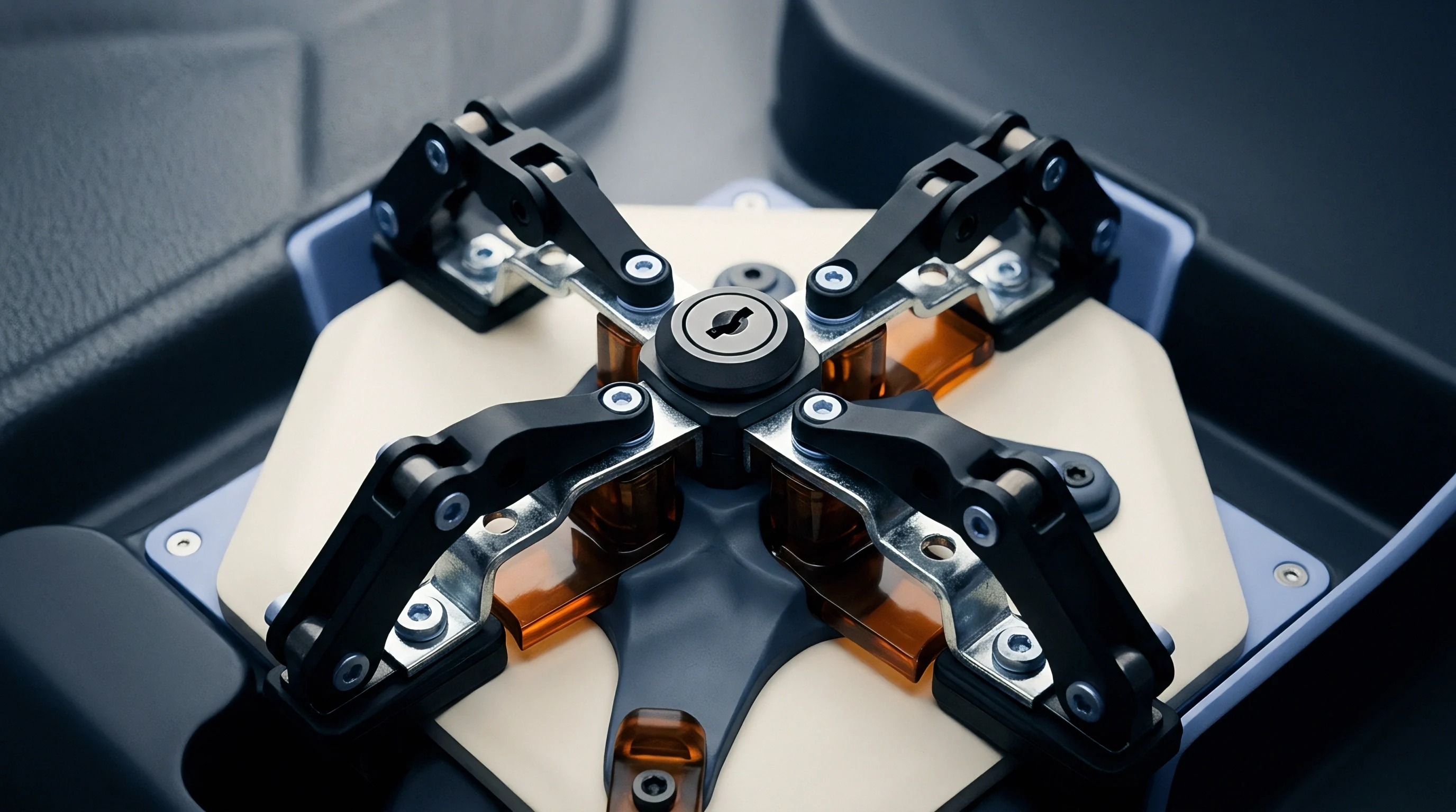
Compression pads act as elastomeric springs between adjacent cells or between cell groups and the enclosure end-plates. These layers take up manufacturing tolerances while imposing a controlled normal stress across the active faces. Maintaining that pressure window preserves electrical contact integrity, keeps interfacial thermal resistance low, and discourages localized lithium plating, with cell geometry largely dictating overall stack stiffness.
Initial Loading Boundaries
Pre-loads are set primarily to keep adjacent cell faces from sliding against one another under shock and vibration. For pouch cells, assembly pre-charge stress generally falls between 0.05 MPa and 0.20 MPa. Prismatic cells, housed in rigid metal cans, withstand higher assembly loads, typically between 0.20 MPa and 0.60 MPa.
Establishing the correct lower boundary ensures sufficient retention remains even at cold temperatures, when thermal contraction shrinks cell dimensions.
Initial compression also flattens surface asperities across pouch foils and aluminum prismatic casings. Microscopic surface gaps increase interfacial thermal impedance. Sufficient pre-load pushes thermal gap fillers or elastomeric pads into intimate contact with cooling plates, though over-tightening during pack build exhausts pad compliance, leaving insufficient travel to absorb subsequent cell swelling.
An initial pre-charge stress of 0.20 MPa applied to microcellular foam drops to 0.14 MPa within 100 hours at 45 degrees Celsius under continuous strain.
Mechanical Constraints in Module Enclosures
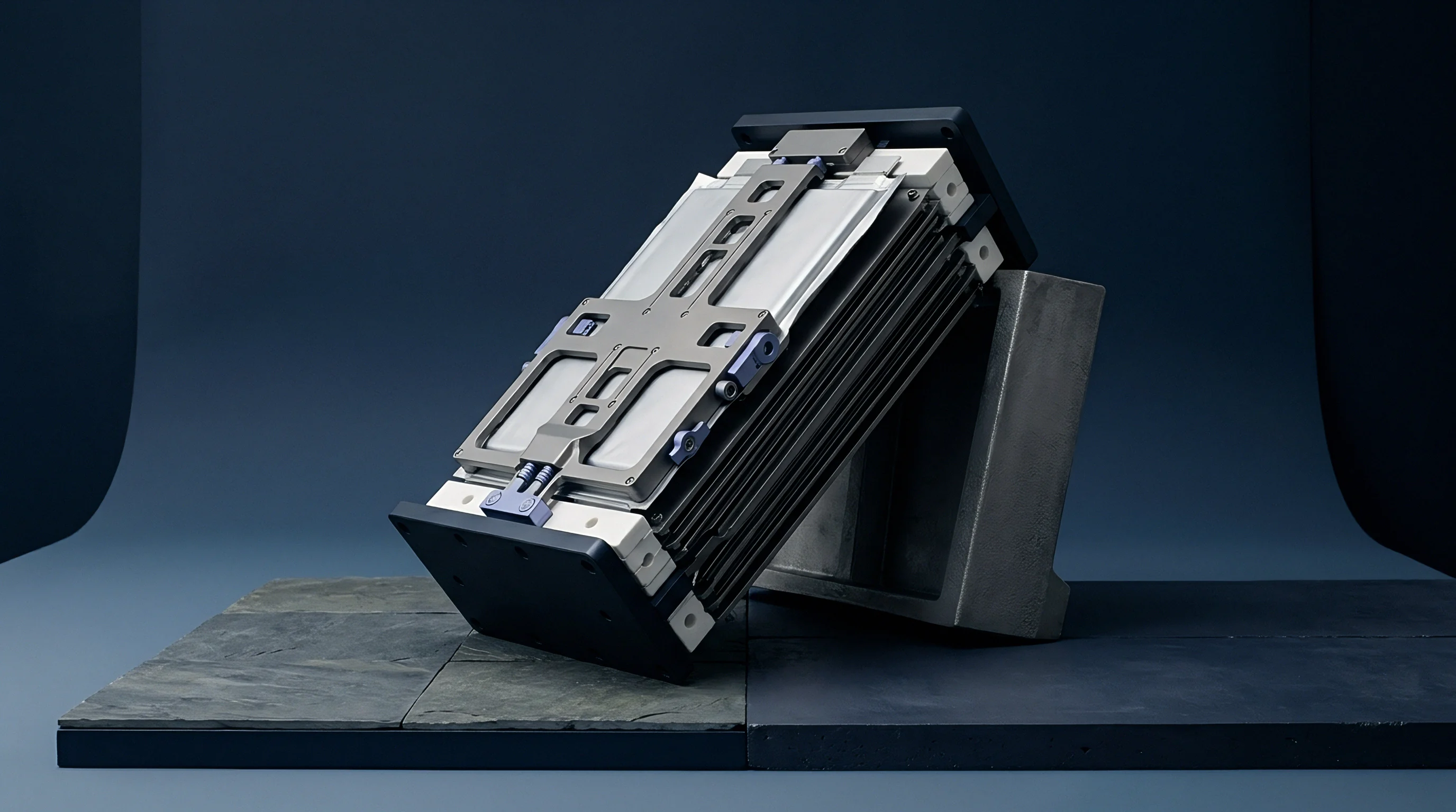
Rigid aluminum end-plates tied together by steel rods or side bands create a fixed spatial envelope. The structural enclosure holds longitudinal pack growth to micrometer-level tolerances. As cells swell during charge cycles, stack strain shifts directly into pad compression and end-plate bending.
End-plate flexure produces an uneven pressure profile across the cell face. Compression peaks along the perimeter edges near the structural ties, while the middle of the plate unloads. This pressure imbalance drives localized variations in current density, accelerating electrode degradation toward the center of the cell.
Module structural design targets end-plate deflection under 0.50 mm at maximum end-of-life expansion forces to maintain uniform contact across every cell layer.
Underestimating end-plate bending or miscalculating initial foam compression leads to yielded tie-rods, bowed module covers, or ruptured pouch seals.
Relaxation
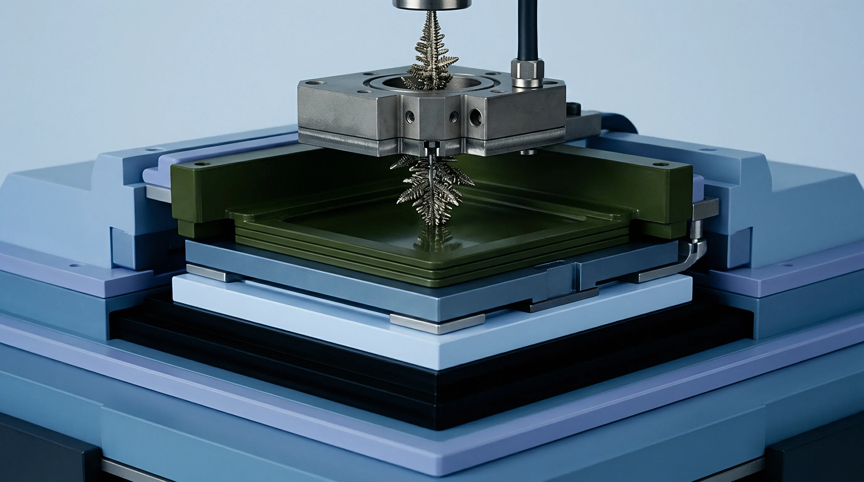
Under constant compressive displacement, polymer foams lose resistive force over time as polymer chains rearrange under load. In a battery module, this viscoelastic relaxation produces a steady decline in retention pressure during storage periods, well before any electrochemical swelling takes place.
Microcellular polyurethane, silicone sponge, and closed-cell ethylene propylene diene monomer foams exhibit markedly different relaxation behaviors under sustained mechanical and thermal load. Silicone foams retain compressive load far better than polyurethanes across broad temperature ranges. Failing to account for this time-dependent relaxation risks losing retention force entirely at cold operational temperatures or generating excessive stress spikes at high temperatures.
Constitutive Viscoelastic Formulations
Modeling time-dependent stress relaxation relies on Maxwell elements arranged in parallel. The Generalized Maxwell model, written as a Prony series, captures the compressive relaxation modulus over time at constant strain:
E(t) = E_infinity + SUM
Where E_infinity is the long-term equilibrium modulus, E_i represents the relaxation strength of the i-th Maxwell element, and tau_i denotes its characteristic relaxation time constant. Extracting these parameters requires multi-stage stress relaxation testing across temperatures from -20 degrees Celsius to 65 degrees Celsius.
When compressive strain surpasses roughly 25 percent, viscoelastic response turns nonlinear. In that regime, the relaxation modulus depends on the applied strain, requiring hyper-viscoelastic models such as coupled Ogden or Mooney-Rivlin strain energy functions paired with hereditary integral formulations.
Temperature and Time Equivalence
Higher operating temperatures accelerate elastomeric relaxation significantly. The Arrhenius relationship or the Williams-Landel-Ferry formulation converts high-temperature creep measurements into equivalent long-term performance at ambient conditions, scaling the response time via a thermal shift factor, a_T:
log10(a_T) = -C1 (T – T_ref) / (C2 + T – T_ref)
Empirical fits determine material constants C1 and C2 relative to a reference glass transition temperature T_ref. Through time-temperature superposition, 1,000-hour laboratory testing at 60 degrees Celsius can project 10-year force retention at 25 degrees Celsius. Overlooking this thermal sensitivity leads to substantial underestimates of clamping loss in packs deployed in warm climates.
| Material Type | Density (kg/m3) | Initial Modulus (MPa) | Compression Set 70C (%) | Force Retention 10 Year (%) |
|---|---|---|---|---|
| Microcellular Polyurethane | 240 – 400 | 0.35 – 1.20 | 12 – 25 | 45 – 60 |
| Silicone Sponge Foam | 350 – 550 | 0.50 – 1.80 | 3 – 8 | 75 – 88 |
| EPDM Foam closed cell | 150 – 300 | 0.20 – 0.70 | 20 – 35 | 30 – 45 |
| Aerogel Polyurethane Composite | 180 – 280 | 0.80 – 2.50 | 15 – 30 | 50 – 65 |
Understanding degradation modes requires evaluating how environmental factors affect structural integrity over operational lifespans.
- Stress Relaxation Decay reduces initial mounting force over extended dwell periods, lowering interface pressure on unswollen cell walls.
- Permanent Compression Set destroys recoverable spring margin, preventing the pad from expanding when cells contract during cold discharge cycles.
- Cell Thickness Mismatch Strain concentrates localized load onto thick cell centers, inducing spatial gradients in viscoelastic modulus loss.
- Thermal Acceleration Drift shifts polymer transition points, triggering rapid mechanical softening during high-temperature fast-charging events.
Pad thickness selection balances the maximum permissible swollen cell stress against the minimum retention force needed to resist vibration sliding.
Room-temperature compression set figures below five percent do not guarantee decade-long retention; operational temperatures above 45 degrees Celsius double effective relaxation rates within months.

Interphase
Growth of the solid electrolyte interphase represents the primary source of irreversible cell swelling. During each charge, lithium intercalates into the anode lattice, expanding it reversibly. Simultaneously, parasitic reduction reactions decompose electrolyte solvents at active material interfaces, precipitating insoluble compounds that permanently increase the electrode stack thickness.
While reversible intercalation breathing subsides upon discharge, irreversible interphase growth accumulates monotonically across thousands of cycles, risking crushed separator pores if expansion space runs out. Modeling module mechanics requires treating both mechanisms together.
Reversible and Irreversible Volume Changes
Cyclic breathing occurs on top of long-term dimensional growth. Reversible thickness changes track state of charge and crystallographic phase shifts within the active materials. Graphite anodes undergo discrete lattice expansions across staging transitions, expanding by up to 10 percent in unit cell volume from C6 to LiC6.
Irreversible expansion follows square-root kinetics with time, governed by solvent diffusion through the passivating interphase. Total cell thickness over N cycles follows:
t_cell(N, SOC) = t_0 + Delta_t_rev(SOC) + k_SEI sqrt(t_time) + k_cycle N
Where t_0 is fresh cell thickness, Delta_t_rev is state-of-charge dependent reversible expansion, k_SEI represents time-dependent passivation layer thickness gain, and k_cycle captures mechanical degradation such as electrode particle cracking and graphite exfoliation.
Silicon Blend Anode Expansion Kinetics
Adding elemental silicon to graphite anodes introduces much larger volume swings. Pure silicon expands roughly 300 percent upon lithiating fully to Li15Si4. Commercial silicon-graphite blends containing 5 to 15 weight percent silicon oxide or silicon-carbon composite exhibit full-charge cell thickness increases between 8 percent and 20 percent over fresh dimensions.
The severe breathing of silicon particles fractures the protective passivation layer, exposing fresh metallic surfaces to liquid electrolyte and driving secondary interphase formation. High-silicon formulations exhibit non-linear irreversible growth kinetics, transitioning from diffusion-limited square-root behavior to reaction-limited linear growth under demanding cycling rates.
| Active Chemistry Pair | Reversible Expansion (%) | Irreversible Growth 1,000 Cycles (%) | Peak Swelling Force Rate (MPa/cycle) |
|---|---|---|---|
| LFP / Graphite | 1.2 – 2.0 | 2.5 – 4.0 | 0.0002 |
| NMC811 / Graphite | 3.5 – 5.0 | 5.0 – 8.5 | 0.0005 |
| NMC811 / Si-C (8 wt% Si) | 8.0 – 12.0 | 14.0 – 22.0 | 0.0018 |
| NCA / Si-C (12 wt% Si) | 11.0 – 16.0 | 18.0 – 28.0 | 0.0025 |
Continuous capacity decay correlates directly with irreversible anode dimensional gain across extended cycling.
Higher initial pre-load pressures compress porous interphase structures, yielding a denser surface film that slows subsequent electrolyte diffusion.
Coupling
Internal mechanical stress directly alters electrochemical reaction rates at the electrode interface. The boundary conditions imposed by compression pads create a coupled feedback loop: external pressure restrains particle cracking and preserves interphase integrity, but excessive mechanical confinement alters local potentials and can induce lithium plating during fast charge cycles.
Predicting pack life requires coupling foam viscoelasticity to stress-dependent electrochemical kinetics. Under heavy mechanical compression, separator pore volume decreases and tortuosity rises, restricting solvated ion migration through the liquid phase.
Stress Dependent Growth Kinetics
Hydrostatic compressive stress suppresses spatial lattice expansion while altering ionic chemical potential gradients. Modified chemical potential equations incorporate mechanical strain energy terms into the Gibbs free energy of interphase formation:
Delta_G_stress = Delta_G_0 – Omega sigma_m
Where Delta_G_0 represents the unconstrained formation energy, Omega is the partial molar volume of the solid interphase compound, and sigma_m is the hydrostatic stress tensor trace. Positive compressive stress lowers the thermodynamic barrier for breakdown reaction progression, theoretically accelerating growth under high pressure. Compressive stress simultaneously reduces solvent transport diffusion coefficients through the compacted interphase layer.
A critical pressure window exists where mechanical suppression of particle cracking balances stress-induced chemical potential drive. Operating within this stress window maximizes cell cycle retention.
Does Elevated Pad Stress Accelerate Capacity Loss?
Excessive pre-loads collapse separator pore structures. At sustained pressures above 1.0 MPa, separator thickness drops noticeably, reducing porosity from 45 percent down below 25 percent. Ionic conductivity falls alongside this porosity drop in accordance with MacMullin relationships.
The resulting impedance rise increases internal cell polarization, triggering localized overpotentials that promote lithium metal plating during cold fast-charging.
Local active-particle crushing also occurs when contact stresses exceed material yield limits. Micro-cracks sever electronic pathways and consume active lithium as fresh surfaces react with solvent.
- Hydrostatic Stress Field modulates molar volume transition energy, altering solid interphase growth rates across active particle boundaries.
- Molar Volume Expansion Rate governs total volumetric expansion, driving internal stack strain against module end-plates.
- Effective Elastic Modulus Drift tracks cell mechanical stiffening as cycling converts soft liquid-saturated graphite into rigid solid breakdown compounds.
- Yield Surface Evolution marks plastic deformation limits of separator membranes under combined thermal and compressive stresses.
Exceeding the maximum compressive pressure threshold specified in cell qualification protocols invalidates standard cycle life performance warranties.
Whether stress-induced interphase densification stabilizes long-term capacity fade faster than separator pore closure accelerates lithium plating remains an active dispute in battery degradation research.
Verification
Extracting accurate inputs for mechanical models requires targeted testing under controlled thermal conditions. Standard quasi-static compression yields simple stress-strain curves, but misses frequency-dependent viscoelastic responses and multi-year relaxation rates. Comprehensive characterization combines dynamic mechanical analysis, long-term stress relaxation dwells, and in-situ cell optical dilatometry.
Coupled simulations require separating the compliance of the elastomeric pad from the swelling signature of the electrochemical cell, which demands rigid, highly calibrated fixtures.

Dynamic Mechanical Analysis and Creep Testing
Oscillatory shear and compression testing isolates elastic storage modulus from viscous loss modulus across frequency domains. Dynamic Mechanical Analysis (DMA) applies sinusoidal displacement at controlled frequencies ranging from 0.01 Hz to 100 Hz across temperatures from -40 degrees Celsius to 80 degrees Celsius. Constructing master curves via time-temperature superposition provides Prony series coefficients needed for finite element simulation solvers.
Long-term creep dwell fixtures utilize high-precision load cells and optical extensometers to record stress relaxation over 3,000-hour test windows. Temperature steps applied during dwell testing validate shift factors derived from short-term DMA sweeps.
In Situ Dilatometry and Pressure Mapping
High-resolution optical displacement sensors track battery dimensional shifts through consecutive charge discharge cycles. Laser dilatometers capture sub-micron thickness alterations while high-frequency tactile matrix sensors record spatial pressure distributions across active cell areas.
Tactile pressure maps identify localized expansion hotspots caused by tab welding offsets, internal structural boundaries, or non-uniform electrode coating thickness. Integrating pressure matrix arrays directly within test module stacks provides real-time boundary condition data needed to validate coupled finite element calculations.
Executing accurate parameter extraction for coupled module simulations follows a defined laboratory sequence.
- Isothermal Stress Dwell measures force degradation curves across multiple constant strain states to fit initial Prony series relaxation amplitudes.
- Frequency Sweep Characterization measures glass transition shifts and storage modulus spectrums using Dynamic Mechanical Analysis.
- Unconstrained Cell Dilatometry determines baseline unconfined reversible and irreversible expansion coefficients across state-of-charge boundaries.
- Coupled Mechanical Dwell Validation subjects full cell-pad stacks to cyclic thermal and electrical loads within rigid load-cell constraints to verify predicted end-of-life pressure curves.
| Test Protocol | Primary Target Parameter | Equipment Standard | Test Duration |
|---|---|---|---|
| Dynamic Mechanical Analysis | Storage / Loss Modulus Spectrum | ASTM E1640 / ISO 6721-1 | 4 to 8 hours |
| Long-Term Stress Relaxation | Prony Series Time Constants | ASTM E328 / ISO 3384 | 1,000 to 3,000 hours |
| In-Situ Laser Dilatometry | Reversible Expansion Coefficient | Internal Procedure / ISO 22489 | 50 to 200 cycles |
| Tactile Pressure Mapping | Spatial Force Distribution Matrix | ASTM F2571 | Real-time continuous |
| Note: Testing performed under controlled nitrogen purge environment to prevent ambient humidity degradation of open-cell elastomeric test specimens. | |||
According to standard testing protocols in IEC 62660-2 clause 6.3, cell swelling limits measured during qualification apply exclusively under baseline compression fixtures loaded at initial manufacturer specified clamping forces.
Sizing
Sizing a compression pad requires balancing initial assembly force against end-of-life swell limits. The pad must remain sufficiently compliant to keep internal stress below structural and electrochemical thresholds once cells reach maximum swelling. At the same time, it must hold enough residual pressure at zero state of charge, cold temperatures, and beginning of life to prevent cell shifting and spikes in thermal contact resistance.
Calculations require integrating thermal expansion tolerances, manufacturing thickness variations, structural housing deflection, viscoelastic pad creep loss, and electrochemical interphase accumulation into a unified spatial equation.
Tolerance Stack up and Structural Deflection
Manufacturing variances across cell thickness, end-plate flexure, and housing dimensions determine the net compression gap. Statistical root-sum-square analysis provides realistic assembly tolerance limits compared to overly conservative worst-case linear additions. Total gap tolerance range delta_G calculates as:
delta_G = sqrt( sum( t_cell_tol^2 ) + t_plate_tol^2 + t_pad_tol^2 )
Where t_cell_tol represents individual cell thickness tolerance, t_plate_tol represents end-plate manufacturing variation, and t_pad_tol is uncompressed pad thickness tolerance. The compression pad must absorb this entire dimensional variance envelope while maintaining net interface pressure within designated operational limits.

Worked Sizing Calculation for a Twelve Cell Prismatic Module
Consider an automotive LFP pack containing twelve 100 Ah prismatic cells held between end-plates. Fresh cell thickness measures 40.00 mm with a manufacturing tolerance of plus or minus 0.15 mm per cell. Unconstrained irreversible growth at 1,500 cycles reaches 3.0 percent, adding 1.20 mm per cell.
Reversible charge expansion adds 0.80 mm per cell at 100 percent state of charge. Total unconstrained cell stack expansion equals 12 cells multiplied by 2.00 mm expansion, yielding 24.00 mm total stack expansion.
Nominal stack width for twelve cells equals 480.00 mm. Statistical stack variation across twelve cells calculated via root-sum-square equals sqrt(12 0.15^2) = 0.52 mm. The rigid enclosure cavity provides 510.00 mm fixed length, leaving 30.00 mm total nominal space for compression pads.
Eleven inter-cell pads plus two end pads yield 13 pad spaces, providing 2.308 mm nominal uncompressed pad thickness space per location.
Select a microcellular polyurethane foam pad with an uncompressed nominal thickness of 3.20 mm and an initial compression modulus of 0.60 MPa at 28 percent strain. Initial installed compression per pad equals 3.20 mm minus 2.308 mm, resulting in 0.892 mm deflection (27.87 percent strain). Initial assembly stress equals 0.60 MPa 0.2787 = 0.167 MPa, satisfying the minimum pre-load requirement of 0.10 MPa to prevent dynamic sliding.
Account for long-term viscoelastic relaxation: polyurethane retains 55 percent of initial force after 10 years, dropping structural retention capability down to 0.092 MPa equivalent baseline stress. At end-of-life, 24.00 mm stack growth distributed across 13 pads compresses each pad by an additional 1.846 mm. Total pad deflection reaches 0.892 mm plus 1.846 mm = 2.738 mm, representing 85.56 percent strain relative to uncompressed 3.20 mm pad thickness.
In this extreme strain regime, microcellular foam enters solid compression, raising the effective tangent modulus from 0.60 MPa up to 12.00 MPa. Final compressive stress calculated via hyperelastic strain energy functions reaches 4.85 MPa, exceeding the maximum allowable cell casing crush threshold of 1.20 MPa.
To resolve this over-pressure failure, the architect increases the uncompressed pad thickness to 4.50 mm and expands module cavity allocation to 530.00 mm. Nominal gap space per pad increases to 3.846 mm. Initial strain drops to 14.53 percent (0.654 mm deflection), yielding an initial pre-charge stress of 0.087 MPa.
Under full 1.846 mm end-of-life cell expansion, total pad compression reaches 2.500 mm, corresponding to 55.55 percent strain. Final end-of-life stress lands at 0.78 MPa, safely under the 1.20 MPa maximum allowable limit while maintaining 0.12 MPa cold minimum retention pressure post-creep relaxation.
Selecting compression pad dimensions without accounting for non-linear high-strain densification leads directly to module structural deformation, tie-rod shear failure, or accelerated interphase degradation driven by excessive internal cell compression.