Predictive Thermal Fatigue Modeling for Conformal-Cooled Large Format Aluminum Battery Tray Molds
Predictive thermal fatigue modeling aligns conformal cooling placement with transient plastic strain boundaries to extend aluminum tray mold life beyond 50,000 cycles.


Gradient
Large-format aluminum molds for battery trays absorb sharp thermal shocks on every injection or compression shot. When molding structural enclosures up to two meters long, cavity surface temperatures can swing 180 degrees Celsius within a fifteen-second injection window. Forged 6061-T6 and high-strength 7075-T6 shed heat fast ~ thermal conductivity hits 167 Watts per meter-Kelvin, well above P20 or H13 tool steels.
But that rapid dissipation creates steep local gradients across cavity transitions, rib intersections, and perimeter clamps. As adjacent sections expand at different rates, constraint stresses push past the alloy’s yield strength at peak operating temperature.
Tracing these gradients requires following transient heat flux through fill, pack, and active chill. Contact with molten alloy at 680 degrees Celsius ~ or hot thermosets ~ spikes heat flux through the cavity skin past 3.5 Megawatts per square meter. In high-pressure die casting and semi-solid molding of battery trays, rapid heat extraction is essential to hold floor-pan flatness within tolerance.
Without balanced cooling, severe gradients develop between the surface and the core metal just two millimeters behind it. When that hot surface tries to expand against the colder backing matrix, the outer skin yields in compression.

Thermal Shock Loading and Spatial Distribution
Temperature splits appear most aggressively around perimeter seal grooves, internal ribbing, and mounting bosses, where abrupt thickness changes skew heat transfer. Deep ribs on the tray part require concentrated cooling to head off shrinkage porosity. If standard straight-drilled channels miss those features, localized heat pools in the tool block.
The skin over a hot spot can linger above 240 degrees Celsius while nearby zones drop below 110 degrees Celsius before demolding. That 130-degree Celsius differential over less than thirty millimeters sets up shear strains that destabilize the aluminum grain boundaries.
Conformal circuits address macro-level thermal buildup by routing fluid paths directly along the tray profile. Holding a fixed distance from the cavity wall keeps thermal resistance uniform over the molding face. Across a tool of this scale, minor shifts in thickness heavily skew the gradient: moving cooling lines just three millimeters farther from the surface drives peak surface stress up by forty-two percent during dwell.
Boundary element work indicates that gradient steepness dictates plastic strain amplitude per cycle, leaving peak surface temperature as the primary variable for estimating tool life.
| Material Grade | Thermal Conductivity (W/m·K) | Coefficient of Thermal Expansion (10⁻⁶/K) | Yield Strength (MPa) | Elastic Modulus (GPa) | Critical Cyclic Plastic Strain Limit (%) |
|---|---|---|---|---|---|
| Forged AA6061-T6 | 167 | 23.4 | 275 | 68.9 | 0.18 |
| Forged AA7075-T7651 | 130 | 23.2 | 460 | 71.0 | 0.12 |
| C17200 Beryllium Copper | 105 | 17.5 | 880 | 128.0 | 0.32 |
| Tool Steel AISI P20 | 29 | 12.8 | 850 | 205.0 | 0.08 |
| Tool Steel AISI H13 | 24 | 10.4 | 1220 | 210.0 | 0.06 |
Tooling in aluminum involves a persistent compromise between heat transfer and mechanical strength. High-strength grades like 7075-T7651 carry higher initial elastic loads, yet their precipitates over-age rapidly once surface temperatures pass 160 degrees Celsius. As metastable Eta-prime precipitates convert to the stable Eta phase, local yield strength falls by as much as thirty-five percent across fifty thousand cycles.
Alloy 6061-T6 starts at a lower yield threshold but provides greater ductility, tolerating thermal shock better under moderate cyclic strain. In isolated high-flux areas, copper-beryllium inserts damp local spikes while preserving structural rigidity.
Peak surface heat flux during fluid injection reaches 3.8 Megawatts per square meter when molding 2.2-meter aluminum pack enclosures.
The decay rate of the thermal gradient during cooling dictates both cycle speed and residual stress. High-flow conformal circuits can draw the cavity skin out of compressive yield before mold opening. If fluid velocity drops or flow slips into a laminar regime, however, heat radiates back from the core.
That rebound reheats the surface and traps high residual tension in the cavity face at ejection. Moving back and forth between compression on heating and tension on cooling drives low-cycle thermal fatigue.
Reliable fatigue predictions depend on transient boundary conditions derived from coupled 3D conjugate heat transfer and elastic-plastic FEA. Steady-state models fail on tools of this geometry. With high surface-to-thickness ratios, convective heat transfer coefficients vary dramatically ~ from roughly 2,000 Watts per square meter-Kelvin in conventional drilled lines to upwards of 12,000 Watts per square meter-Kelvin in turbulent conformal passages.
Calculating strain ranges requires mapping these changing film coefficients across the cavity profile.
Once thermal gradients are resolved, strain energy densities across the grain structure can be isolated. Analysis shifts from thermal distribution to deformation mechanics, where plastic strain amplitude determines whether an insert survives fifty thousand shots or five hundred thousand. How cleanly the tooling manages thermal spikes during the first three seconds of injection decides how quickly slip bands coalesce into visible crazing.
A lingering unknown in boundary layer behavior is the specific fluid velocity threshold where micro-cavitation around tight conformal bends accelerates erosion-corrosion under cyclic thermal strain.

Transient
Thermomechanical deformation accumulates through coupled elastic-plastic cycles on each shot. As the heated cavity face expands against the cooler core, physical restraint converts that expansion into direct mechanical strain. Aluminum loses strength quickly above 150 degrees Celsius, so thermal compressive strain soon passes the proportional limit, driving surface metal into plastic yield during fill.
During cooling and ejection, the cavity face drops toward baseline temperature and begins contracting. Because it deformed plastically while hot, it cannot return to its original dimensions; the surrounding elastic core forces the surface into severe residual tension instead. Each cycle works the cavity face through a reversed or mean-shifted plastic strain loop.
The span of that hysteresis loop defines the cyclic plastic strain range ~ the decisive metric in thermal fatigue analysis.

Strain-Life Formulation and Hysteresis Behavior
Assessing low-cycle fatigue in aluminum tooling requires adjusting classical Coffin-Manson strain-life equations for temperature-dependent elastic moduli, strain-rate sensitivity, and mean stress relaxation. Total strain amplitude resolves into elastic and plastic components:
Total strain range combines elastic strain ~ stress amplitude divided by dynamic modulus ~ and plastic strain, which scales with the fatigue ductility coefficient and cycles to failure. In large battery pack tooling, operational strain ranges generally sit between 0.15 percent and 0.45 percent. Since aluminum exhibits no true fatigue limit at elevated temperatures, each shot takes an irreversible bite out of matrix life.
Morrow and Smith-Watson-Topper formulations correct Coffin-Manson values for the mean tensile stresses left in the mold skin during cooling. Tensile forces pry open micro-cracks along persistent slip bands. When coolant temperatures fluctuate or run high, residual tension can reach sixty percent of room-temperature yield strength, cutting projected tooling life by more than half.
- Thermal Expansion Mismatch Strain occurs when aluminum cavity faces expand against lower-expansion steel alignment pins, side-actions, or support pillars, driving local shear strain concentrations.
- Transient Compressive Yielding develops during rapid injection when thermal spikes drive surface yield strength below the induced thermal stress.
- Cooling Phase Tensile Inversion takes place during ejection as the contracting surface is restrained by the cold core, flipping compressive strain into residual tension.
- Microstructural Over-Aging Drift progresses over long production campaigns as steady thermal exposure coarsens precipitates and degrades fatigue resistance.
- Creep-Fatigue Interaction accumulates during extended dwell times at peak temperature, adding time-dependent plastic strain to cyclic damage.
Non-isothermal testing confirms that the phasing between thermal and mechanical strain cycles dictates fatigue life. Out-of-phase fatigue ~ maximum compressive strain coinciding with peak temperature ~ governs the cavity surface. Yielding under compression at operating heat produces high residual tensile stress once the block cools down.
Over repeated cycles, this mechanism fractures the protective surface oxide layer, creating micro-notches where cracks take hold.
In-phase fatigue dominates internal conformal channels, where peak tensile stresses coincide with peak fluid thermal loads. In this environment, coolant exposure interacts with cyclic mechanical tension to accelerate stress corrosion cracking along channel bores. Comprehensive predictive modeling must account for both out-of-phase damage at the molding face and in-phase fatigue within internal cooling lines.
Tooling life drops by fifty percent for every twenty-degree Celsius rise in peak cavity surface temperature above the alloy precipitation threshold.
Cumulative damage is tracked using Miner’s rule modified with non-linear strain corrections. Real-world duty cycles introduce irregular strain blocks through shift changes, press shutdowns, and cold start-ups. Cold starts produce particularly severe strain ranges because the thermal gradient between the ambient cavity face and circulating fluid is at its widest.
Pre-heating aluminum tooling to 80 to 100 degrees Celsius before running production dampens these start-up spikes and protects tool longevity.
FEA workflows map transient stress tensors across solid mesh models of the tool body. Regions with steep thermal gradients ~ such as deep perimeter seal walls and cross-member pockets ~ demand mesh refinement down to 0.2 millimeter node spacing. The solver tracks local multiaxial stress states using Von Mises equivalent strain or critical plane models to identify likely crack initiation sites before cutting metal.
Restraining transient strain loops requires pairing the thermal layout directly to local section thickness. Once operating strains cross the alloy’s elastic threshold, insert life depends almost entirely on how accurately the cooling circuits follow surface geometry.
In shop practice, pre-heating large aluminum tooling to ninety degrees Celsius cuts start-up plastic strain amplitudes roughly in half compared to cycling from ambient.


Channel
Conformal cooling circuits transform fatigue management by following complex part geometries directly. Conventional gun-drilled lines result in varying distances between fluid bores and the cavity face, leaving persistent hot spots in deep pockets and rib intersections. Conformal passages maintain a uniform offset across the tool, balancing heat extraction and flattening peak thermal stresses on the surface.
Engineering conformal passages in large aluminum blocks means balancing heat removal, line pressure drop, and structural integrity. Conformal circuits are typically produced via powder bed fusion, directed energy deposition, or layered vacuum brazing. Vacuum brazing 6061 or 7075 plates allows machining fluid channels directly into internal plate faces prior to bonding.
This produces clean internal flow surfaces and avoids the micro-porosity common in large-envelope additive builds.

Which Channel Cross Section Suppresses High-Cycle Thermal Rib Fatigue?
Channel cross-section governs both heat transfer rates and localized mechanical stress concentrations. Round bores offer predictable fluid dynamics and excellent pressure containment, but they pull heat unevenly across broad surfaces. Profiles like teardrops, ellipses, or filleted rectangles align more cooling area directly beneath the cavity surface.
Flattened profiles increase heat transfer over the conduit crown, lowering peak surface temperatures by as much as 35 degrees Celsius compared to round channels at the same depth.
Rectangular passages with sharp transitions introduce severe corner stress concentrations. Internal fluid pressure alongside thermal expansion generates cyclic tension at tight radii. To keep cracks from initiating inside the cooling channel and propagating toward the cavity, internal fillets should have a radius of at least forty percent of the channel width.
Hydrostatic line pressure adds cyclic hoop stress, establishing a hard floor on the safe offset distance to the cavity face.
| Cross-Section Geometry | Heat Transfer Coefficient Multiplier | Relative Pressure Drop per Meter (%) | Internal Stress Concentration Factor (Kt) | Minimum Cavity Wall Offset (mm) |
|---|---|---|---|---|
| Standard Round (10mm Diameter) | 1.00 | Baseline (0) | 1.15 | 12.0 |
| Elliptical (14mm x 7mm) | 1.38 | +22 | 1.32 | 8.5 |
| Filleted Rectangular (12mm x 6mm, R2) | 1.62 | +45 | 1.68 | 8.0 |
| Teardrop Profile (10mm Major Axis) | 1.25 | +12 | 1.21 | 10.0 |
| Dual-Parallel Micro-Conduits (6mm) | 1.85 | +110 | 1.10 | 6.0 |
Hydraulic parameters must sustain turbulent flow without degrading the channel walls. Heat transfer follows the Dittus-Boelter relationship, where a Reynolds number exceeding 10,000 is required to strip the laminar boundary layer. In aluminum tools, water-glycol velocities of 2.5 to 4.0 meters per second yield convective heat transfer coefficients reaching 11,000 Watts per square meter-Kelvin.
Exceeding 4.5 meters per second, however, invites erosion-corrosion at elbows and transitions, thinning the parent metal and risking premature breaches.
Validating conformal cooling circuits requires several verification steps before the tool goes into production.
- Run CFD analysis across the network to establish flow velocities, pressure drops, and film coefficients across each sub-circuit.
- Size branch diameters across parallel circuits to balance fluid distribution and prevent dead zones in complex loops.
- Run transient conjugate heat transfer simulations linking fluid behavior to the aluminum body to capture peak thermal swings.
- Transfer thermal stress fields into multiaxial fatigue models to verify that channel wall cyclic strain remains within the elastic limit.
- Proof-test completed inserts hydraulically at 1.5 times maximum working pressure to confirm vacuum-braze joint integrity.
- Check circuit flow with ultrasonic meters and verify heat extraction against thermal imaging during initial NPI tryouts.
Weaving conformal lines around ejector pins, side actions, and alignment bushings demands tight geometric controls. Uncooled regions around ejector pins create localized heat buildup that triggers galling and material pickup. Wrapping micro-conformal circuits around ejector pin sleeves with a minimum three-millimeter clearance envelope prevents pin seizure while stabilizing part dimensions around the perimeter.
Standard ISO 19980 compliance guidelines mandate hydraulic proof testing at 1.5 times maximum system pressure to verify internal cooling line integrity.
Vacuum-brazed laminated assemblies perform well structurally when designed with stepped joint interfaces and high-purity silicon-aluminum filler foil. A sound braze in 6061 can attain ninety percent of parent metal tensile strength following post-braze T6 heat treatment. However, inadequate surface preparation or residual machining oils will cause unbonded voids.
These voids serve as internal stress raisers, inviting delamination along the braze plane under thermal cycling.
Maintaining coolant chemistry is essential for channel durability. Deionized water with proper corrosion inhibitor packages stops galvanic degradation between aluminum inserts, steel backing plates, and brass manifold fittings. Internal oxide fouling acts as a thermal barrier, capable of reducing local heat transfer coefficients by forty percent within ten thousand cycles.
Maintaining clean, conditioned fluid preserves the tool’s baseline cooling capacity.
A molding plant incurred severe downtime costs when uninhibited water pitted a 7075-T6 core insert internally, producing pinhole leaks into the molding cavity after just fourteen thousand cycles.

Crack
Thermal fatigue in aluminum tooling follows an established degradation curve, commonly observed as heat crazing. Cyclic strain progressively concentrates along crystallographic slip planes, eventually surfacing as a network of fine micro-cracks in high-flux cavity regions. This network impairs part surface quality, causes demolding drag through mechanical keying, and will propagate into the structural core if left unaddressed.
Prior to visible cracking, the alloy matrix undergoes persistent slip band development, precipitate coarsening, and grain boundary sliding. At peak operating temperatures, enhanced atomic mobility lets dislocations organize into sub-grain boundaries. Strengthening precipitates ~ Mg2Si in 6061 or MgZn2 in 7075 ~ coarsen and shed coherency with the aluminum matrix.
The resulting localized softening creates precipitate-free zones along grain boundaries, concentrating cyclic plastic strain in narrow bands.
Crack Propagation Physics and Damage Progression
After micro-cracks nucleate at grain boundaries or tool marks, growth transitions to non-linear fracture mechanics regimes described by parameters like the cyclic J-integral. Propagation advances through a dual mechanism: mechanical tensile tearing during the cooling phase coupled with crack-tip oxidation. Exposure to air oxidizes the freshly sheared metal exposed at the tip under tensile stress; the resulting brittle film fractures on the subsequent cycle.
Tooling surface topography directly influences crack initiation. Milling scallops, cutter marks, and EDM recast layers serve as built-in stress risers. Dropping surface finish from Ra 0.2 micrometers to Ra 1.6 micrometers reduces thermal fatigue life by more than forty percent.
EDM recast layers present an acute risk: the brittle, micro-fissured surface layer must be removed by polishing or chemical etching before running production parts.
- Grade 1 Micro-Craze ~ isolated hairline surface cracks under 0.05 millimeters deep, detectable only via fluorescent penetrant inspection and without cosmetic impact on molded parts.
- Grade 2 Network Crazing ~ interconnected surface fissures up to 0.3 millimeters deep that transfer faint witness marks to the tray without compromising insert stability.
- Grade 3 Deep Fatigue Fissures ~ dominant crack paths extending beyond 1.2 millimeters into the substrate, causing ejection drag and requiring laser cladding repair.
- Grade 4 Structural Fluid Breach ~ fatigue fissures that penetrate into internal conformal cooling channels, venting coolant directly into the cavity.
Non-destructive evaluation enables toolrooms to monitor crack propagation without destructively sectioning inserts. High-frequency eddy current arrays pick up shallow surface flaws through coatings or release films. Ultrasonic surface wave testing measures crack depth while assessing stress zones around internal conformal channels.
Conducting NDT inspections every five thousand cycles generates an empirical wear profile for each tool component.
Repairing crazed tooling demands tightly controlled energy input, such as micro-welding or laser powder cladding. Conventional TIG welding introduces excessive bulk heat, risking tool warpage, distortion of conformal cooling bores, and deep over-aged zones. Fiber laser cladding limits heat input while depositing matching aluminum alloys or copper-nickel wire into routed relief channels.
Rapid solidification produces a refined microstructure that resists secondary crazing.
Surface barrier treatments help protect aluminum tooling from thermal shock and rapid oxidation. Hard anodizing, PVD chromium nitride, and electroless nickel-boron act as thermal barriers; an anodized film can reduce peak transient substrate temperatures by as much as thirty degrees Celsius. However, heavy anodized coatings exhibit poor strain compliance and fracture under cyclic thermal expansion, making thin duplex systems the standard choice under severe thermomechanical cycling.
Field failures in aluminum tooling frequently generate debate over whether early cavity crazing is an inherent property of alloys running over one hundred fifty degrees Celsius or a sign of poor thermal management.
Warrant
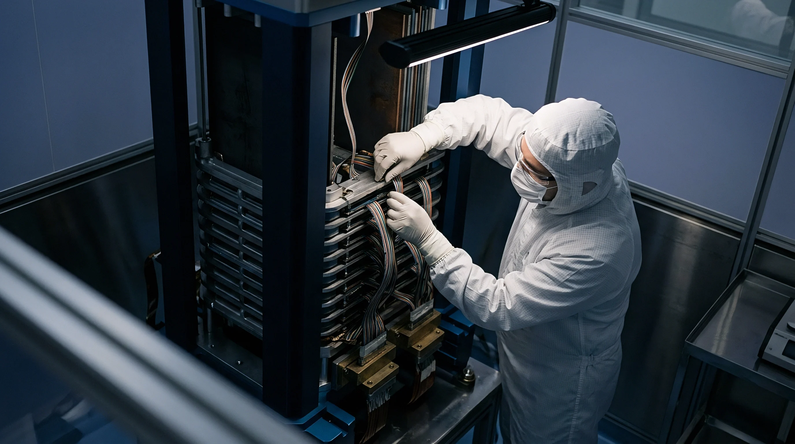
Specifying conformal-cooled aluminum tooling for EV battery trays requires translating thermal fatigue simulations into enforceable contract language. Automotive OEMs and Tier-1 suppliers regularly target guaranteed lifespans between fifty thousand and three hundred thousand cycles. Aluminum delivers faster cycle times and lower NRE tooling expense than monolithic steel dies, but its finite fatigue envelope demands concrete contractual terms covering process parameters, maintenance intervals, and rebuild liability.
Tooling warranties must bind to the boundary conditions assumed in the initial engineering models. Fatigue forecasts remain valid only while the press operates within calibrated flow rates, peak surface temperatures, cycle durations, and clamp forces. Diverting coolant flow to other plant circuits spikes cavity temperatures past design thresholds and precipitates early failure.
Solid tooling agreements stipulate continuous data logging of supply temperatures, flow volumes, line pressures, and embedded thermocouple readings as a condition of warranty standing.
NRE Amortization and Life-Cycle Economics
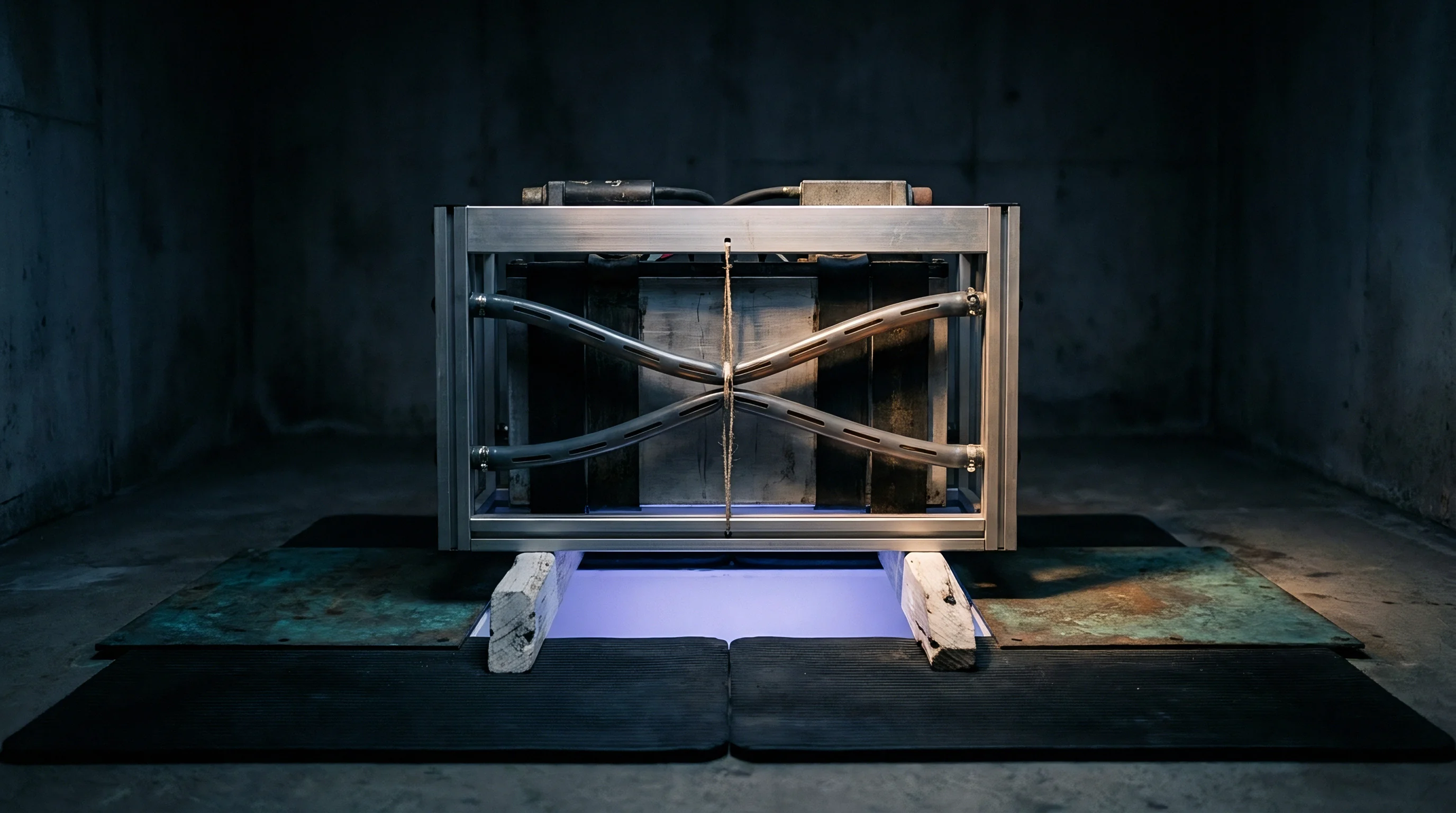
Calculating the economics of aluminum tooling involves balancing initial NRE savings and cycle-time reductions against the cost of periodic insert maintenance. An aluminum mold typically costs thirty to forty percent less to cut and finish than hardened H13 steel, while trimming cycle times by up to thirty-five percent via faster thermal dissipation. Over an automotive production run, those productivity gains comfortably absorb the cost of scheduled laser cladding or replacement sub-inserts.
| Tooling Architecture Strategy | Initial NRE Tooling Cost (USD) | Average Part Cycle Time (Seconds) | Scheduled Refurbishment Interval (Shots) | Total Refurbishment & Maintenance Cost (USD) | Landed Tooling Cost per Tray (USD) |
|---|---|---|---|---|---|
| Monolithic AA6061-T6 (Standard Cooling) | 320,000 | 115 | 25,000 | 180,000 | 5.00 |
| Hybrid AA7075-T6 with Conformal inserts | 450,000 | 78 | 45,000 | 120,000 | 5.70 |
| Vacuum-Brazed AA6061 Conformal Mold | 510,000 | 68 | 60,000 | 95,000 | 6.05 |
| Solid Hardened H13 Tool Steel (Control) | 880,000 | 135 | 150,000 | 40,000 | 9.20 |
Clear division of maintenance responsibility prevents contentious warranty claims once surface crazing inevitably appears. Routine work typically includes scheduled cooling line descaling, O-ring renewal, periodic NDT audits, and light bench polishing of early crazing networks. Rebuilding tasks ~ such as full-cavity laser cladding, CNC remachining, or total core insert replacement ~ belong in explicit service tier provisions established at tool sign-off.
Tooling procurement contracts require unambiguous engineering sign-offs before progress milestones and NRE funds are cleared.
- Predictive Fatigue Simulation File ~ coupled conjugate heat transfer and FEA strain models demonstrating a minimum fatigue safety factor of 1.5 across all molding surfaces.
- Material Certification Dossier ~ mill test certs, ultrasonic volumetric inspection data, and heat treatment charts for every forged billet and insert segment.
- Conformal Circuit Flow Certification ~ sub-circuit flow volumes, delta-P measurements, and thermal imaging records documented during factory buy-off.
- Tooling Operational Envelope Specification ~ defined operational windows for peak cavity temperature, water-glycol chemistry, maximum coolant circuit pressure, and minimum cycle time.
- Refurbishment and Insert Interchangeability Guarantee ~ verified interchangeability ensuring replacement conformal inserts locate within plus or minus 0.015 millimeters without manual bench fitting.
Establishing the true break-even between aluminum and tool steel dies requires factoring in hydraulic press power consumption. Faster heat removal shortens in-press dwell considerably. Trimming dwell from 90 seconds down to 45 seconds can lower power draw on high-tonnage hydraulic presses by as much as forty percent.
Over a production campaign of one hundred thousand battery trays, energy savings alone can surpass sixty thousand dollars ~ offsetting the cost of an entire insert refurbishment.
Predictive fatigue analysis elevates aluminum tooling from a short-run prototyping alternative into a dependable high-volume production solution for EV battery enclosures. Pairing non-linear strain-life calculations with optimized conformal circuits and strict warranty limits allows manufacturers to capture aluminum’s thermal speed while hedging durability risks. When properly engineered, tooling investments achieve predictable throughput across the planned vehicle production run.
Section 14.3 of the Master Tooling Agreement specifies that any mold cavity surface cracking occurring prior to fifty thousand verified production shots places the full financial cost of laser cladding refurbishment or core insert replacement upon the tooling vendor.