Polyurethane Structural Adhesives for Cell to Pack Stack Integrity
Polyurethane structural adhesives balance lap shear strength and thermal compliance in cell-to-pack builds but mandate plasma activation and void control.


Chemistry
Direct cell-to-pack integration eliminates modular sub-assemblies, side plates, and internal mechanical fasteners. Removing these traditional structural boundaries shifts frame loading, thermal management, and mechanical retention directly onto the polymeric adhesive layer. Two-component polyurethanes bridge the gap between rigid epoxies and soft silicones, balancing high lap shear strength with enough compliance to accommodate differential thermal expansion and dynamic swelling over five thousand charge cycles.
The backbone of a two-component structural polyurethane forms through step-growth polymerization of an isocyanate and a polyol. The A-side typically consists of monomeric or polymeric methylene diphenyl diisocyanate with an NCO group content calibrated between thirty and thirty-two percent by weight. The B-side blends a liquid polyol with chain extenders, thermal conductivity fillers, catalysts, moisture scavengers, and flame retardants.
Hydrophobic polybutadiene or bio-based polyether polyols form the matrix to minimize moisture absorption, whereas standard polyester polyols suffer hydrolytic degradation in hot, humid environments, cleaving ester links and leading to severe shear strength loss over extended pack lifespans.
Stoichiometric balance controls crosslink density and final viscoelastic performance. Formulators target an isocyanate index between one point zero three and one point zero eight, maintaining a slight excess of NCO groups to account for trace moisture consumed during mixing while ensuring complete hydroxyl conversion. Polyols with hydroxyl numbers ranging from one hundred ten to two hundred twenty milligrams of potassium hydroxide per gram yield a crosslinked network with a glass transition temperature positioned safely below negative forty degrees Celsius.
Keeping Tg below this limit prevents brittle phase transitions during extreme cold starts, preserving impact resistance and peel strength at sub-zero temperatures.
The structural adhesive layer must sustain eighteen megapascals of lap shear stress while maintaining twenty percent elongation at break across an operating temperature spectrum from negative forty degrees Celsius to eighty-five degrees Celsius.
During incoming inspection of raw polyol drums, testing water content by Karl Fischer titration prevents outgassing during cure. Moisture present in the polyol blend reacts preferentially with raw diisocyanates, generating carbon dioxide bubbles and amine intermediates that yield brittle urea linkages. Microscopic voids formed by carbon dioxide expansion act as stress concentrators, dropping structural fatigue resistance by thirty to fifty percent and creating dielectric breakdown paths between the cell housing and the grounded aluminum tray.

Polyols and Isocyanate Stoichiometry
Raw material purity dictates long-term mechanical survival under continuous vibration. Short-chain diols such as one-four-butanediol or dipropylene glycol act as chain extenders, modulating the ratio of hard to soft segments in the cured matrix. Hard segments derived from MDI and short-chain diols organize into crystalline domains that supply tensile strength and high modulus, while soft segments formed by flexible polyether or polybutadiene chains deliver elastic recovery, damping, and stress relaxation.
Catalysis controls the gelation rate, open time, and strength build cadence on high-speed production lines. Organometallic catalysts such as dibutyltin dilaurate promote the urethane reaction, though regulatory phase-outs of organotin compounds favor bismuth and zirconium carboxylates or delayed-action tertiary amine complexes. An extended open time of eight to twelve minutes gives automated gantry robots enough margin to lay continuous serpentine beads across full tray floors prior to cell insertion.
Reaction kinetics must yield rapid green strength development, reaching two megapascals of lap shear strength within thirty minutes to permit downstream handling without clamping fixtures.

Thermal Conductivity Fillers and Rheological Behavior
Unfilled polyurethane matrices exhibit low intrinsic thermal conductivity, typically measuring zero point two Watts per meter-Kelvin. Formulations engineered for cell-to-pack designs incorporate heavy loadings of crystalline mineral fillers to raise bulk thermal conductivity to between one point two and two point five Watts per meter-Kelvin. High-purity spherical aluminum oxide and synthetic aluminum trihydrate form the standard industrial filler package, added at volume fractions ranging from forty-five to sixty-five percent of the total formulation weight.
Particle size distribution governs bulk viscosity and flow behavior during automated high-pressure dispensing. Multimodal distributions combine coarse alumina particles centered around forty micrometers with fine fractions centered around two micrometers. This packing geometry maximizes thermal path density while preventing particle jamming inside small-orifice nozzles.
Particle surface treatment using silane coupling agents lowers the viscosity of the filled polyol component from eighty thousand millipascal-seconds down to twenty-five thousand millipascal-seconds at a shear rate of ten reciprocal seconds. The resulting fluid exhibits pronounced thixotropic behavior with an index between three point five and five point two, ensuring the dispense bead maintains its tall shape without slumping prior to cell placement.
| Property Parameter | Two-Component Polyurethane | Two-Component Epoxy | Addition-Cure Silicone |
|---|---|---|---|
| Lap Shear Strength (ISO 4587) | 10.5 to 16.5 MPa | 18.0 to 28.0 MPa | 1.2 to 2.8 MPa |
| Tensile Elongation at Break (ISO 527) | 35% to 110% | 2% to 8% | 80% to 220% |
| Young’s Modulus (E) | 120 to 480 MPa | 1500 to 4500 MPa | 2.5 to 12 MPa |
| Thermal Conductivity (ISO 22007-2) | 1.2 to 2.2 W/m·K | 1.0 to 3.0 W/m·K | 1.5 to 3.5 W/m·K |
| Glass Transition Temperature (Tg) | -45°C to -35°C | 55°C to 115°C | -120°C to -50°C |
| Density (Specific Gravity) | 1.6 to 1.95 g/cm³ | 1.5 to 1.85 g/cm³ | 2.1 to 2.7 g/cm³ |
High mineral filler loading presents severe abrasive wear challenges within positive displacement metering pumps and stainless steel fluid conduits. Aluminum oxide particles possess a Mohs hardness of nine, which rapidly erodes hardened tool steel valves, dynamic pump seals, and dispense tips during continuous dispensing. Swapping spherical alumina for surface-treated aluminum trihydrate mitigates pump erosion due to its lower Mohs hardness of three, while adding intrinsic flame retardancy through endothermic thermal decomposition.
Above two hundred degrees Celsius, aluminum trihydrate decomposes endothermically, releasing thirty-four percent of its weight as water vapor to suppress localized thermal runaway propagation across adjacent prismatic cells.

Comparing Mechanical Damping across Structural Polymers
A bond’s mechanical response under high-frequency dynamic loading dictates whether structural joints survive vehicle road inputs. Epoxies supply high static tensile shear strength but lack viscoelastic dissipation mechanisms. When a pack structure undergoes chassis torsion or severe bottom-impact mechanical shock, rigid epoxy joints concentrate stress at bond line edges, driving brittle interfacial cleavage through thin aluminum cell casings.
Structural polyurethanes possess a loss factor tan delta peak calibrated to absorb dynamic impact energy across common vehicle excitation frequencies between ten Hertz and two hundred Hertz.
Silicone adhesives deliver high thermal stability and extreme flexure tolerance, yet their low intrinsic cohesive shear strength demands massive bonding surface areas that defeat energy density targets. Polyurethane structural formulations balance mechanical rigidity with energy dissipation. Tensile elongation values between thirty-five and one hundred ten percent allow the joint to deform elastically during chassis twisting, distributing peak shear stresses evenly across the cell walls rather than concentrating force along outer perimeter bonds.
The operational limits of structural polyurethanes emerge under long-term elevated temperature exposure. Formulations exposed continuously to temperatures exceeding ninety-five degrees Celsius exhibit thermal oxidation of polyether backbones and thermal urethane cleavage. Thermogravimetric analysis demonstrates that standard structural polyurethanes lose mass rapidly when held at one hundred twenty degrees Celsius for extended durations.
Formulators offset thermal degradation by incorporating hindered phenol antioxidants and aromatic phosphite stabilizers, capping long-term continuous thermal exposure limits at eighty-five degrees Celsius to ensure fifteen-year pack design life compliance.
- Interfacial Adhesive Cleavage occurs when surface energy mismatch or organic contamination prevents complete chemical wetting, leaving zero residual polymer on the substrate after failure testing.
- Bulk Cohesive Fracture represents the preferred failure mode where structural failure occurs entirely within the polymer matrix, indicating interface bond strength exceeds internal matrix strength.
- Substrate Aluminum Anodization Delamination develops when native oxide layers under stress fail beneath the chemical bond line, taking surface treatment layers with the cured adhesive mass.
- Filler-Matrix Dewetting manifests under sustained mechanical strain as micro-voids open around un-silanized alumina filler particles, causing gradual stiffness loss and elevated moisture absorption.
Surfaces receiving structural polyurethane adhesive beads require continuous process verification. Raw aluminum prismatic cell casings carry trace cold-rolling oils, aliphatic paraffin lubricants, and variable oxide layer thicknesses. Clean casing surfaces exhibit a native surface energy near thirty-four millinewtons per meter, which is insufficient for robust polyurethane wetting.
Applying atmospheric air plasma treatment immediately prior to adhesive dispensing cleans surface organics and raises substrate surface energy above fifty-four millinewtons per meter. Tear-down evaluations show a 14 percent drop in lap shear strength when atmospheric plasma treatment is omitted prior to dispensing.
Substrate moisture plays a dual role during curing. While heavy water contamination degrades matrix integrity, trace surface hydroxyl functionality created by atmospheric plasma activation enhances covalent siloxane and urethane bonding to the aluminum casing. Plasma processing forms polar hydroxyl and carboxyl surface sites that react directly with open isocyanate groups at the interface, forming covalent chemical bonds that resist moisture ingress and interfacial hydrolytic cleavage over thousand-hour damp heat testing cycles.
Unexpected lot-to-lot cure variation is often attributed to ambient shop-floor humidity fluctuations or minor metering system pressure drops, under the assumption that minor stoichiometric shifts fall within normal polyol hydroxyl number manufacturing allowances.


Joint
Structural stack integrity within cell-to-pack architectures depends on continuous load transfer across hundreds of individual cell surfaces bound to the chassis floor plate. Prismatic and pouch cells do not act as passive rigid blocks; they function as active, dynamic mechanical components that expand, contract, and breathe during duty cycles. The adhesive joint acts as both the primary structural binder holding the pack assembly together and a compliant mechanical buffer absorbing localized cell swelling without transferring destructive compressive forces to external enclosure walls.
Prismatic cell expansion occurs along two primary axes and distinct time horizons. Reversible expansion occurs during every single charge-discharge cycle as lithium ions intercalate into the graphite anode matrix, driving an operational thickness increase of one point five to three percent. Irreversible expansion accumulates over the fifteen-year operational lifespan of the battery system as solid-electrolyte interphase layer growth, lithium plating, and electrolyte oxidation yield permanent stack swelling between five and eight percent of total cell thickness.
Without engineered compliance inside the joint, cumulative expansion across a module-less row of twenty prismatic cells generates tens of kilonewtons of lateral force, exceeding the plastic yield point of outer pack side rails.

Cell Expansion Mechanics and Shear Stress Distribution
Mechanical shear stress within a bonded cell stack concentrates heavily at the outer edges of the bonding interface. Simple lap shear joint models assume uniform stress distribution across the entire embedded bond line, but real cell-to-tray interfaces suffer from severe edge-stress peaking driven by differential flexure of the thin aluminum cooling plate beneath the rigid cell bases. Applying classical Goland-Reissner joint analysis reveals that peak transverse shear stress at the bond termination boundaries can exceed three times the average calculated nominal stress across the joint center.
Dynamic vehicle operation superimposes complex mechanical loads upon static swelling stresses. Chassis twisting subjects the pack enclosure to multi-axis torsional loading, generating cyclic shear deformation along the horizontal adhesive layer. Simultaneously, vertical road shocks send high-acceleration vertical impact pulses through the joint.
The structural adhesive layer must maintain high fatigue endurance, absorbing billions of low-amplitude shear strain cycles without initiating micro-cracks at the stress-concentrated joint edges.
A failure along the bond line exposes the entire pack structure to mechanical damage.
How Does Cell Swelling Induce Adhesive Fatigue?
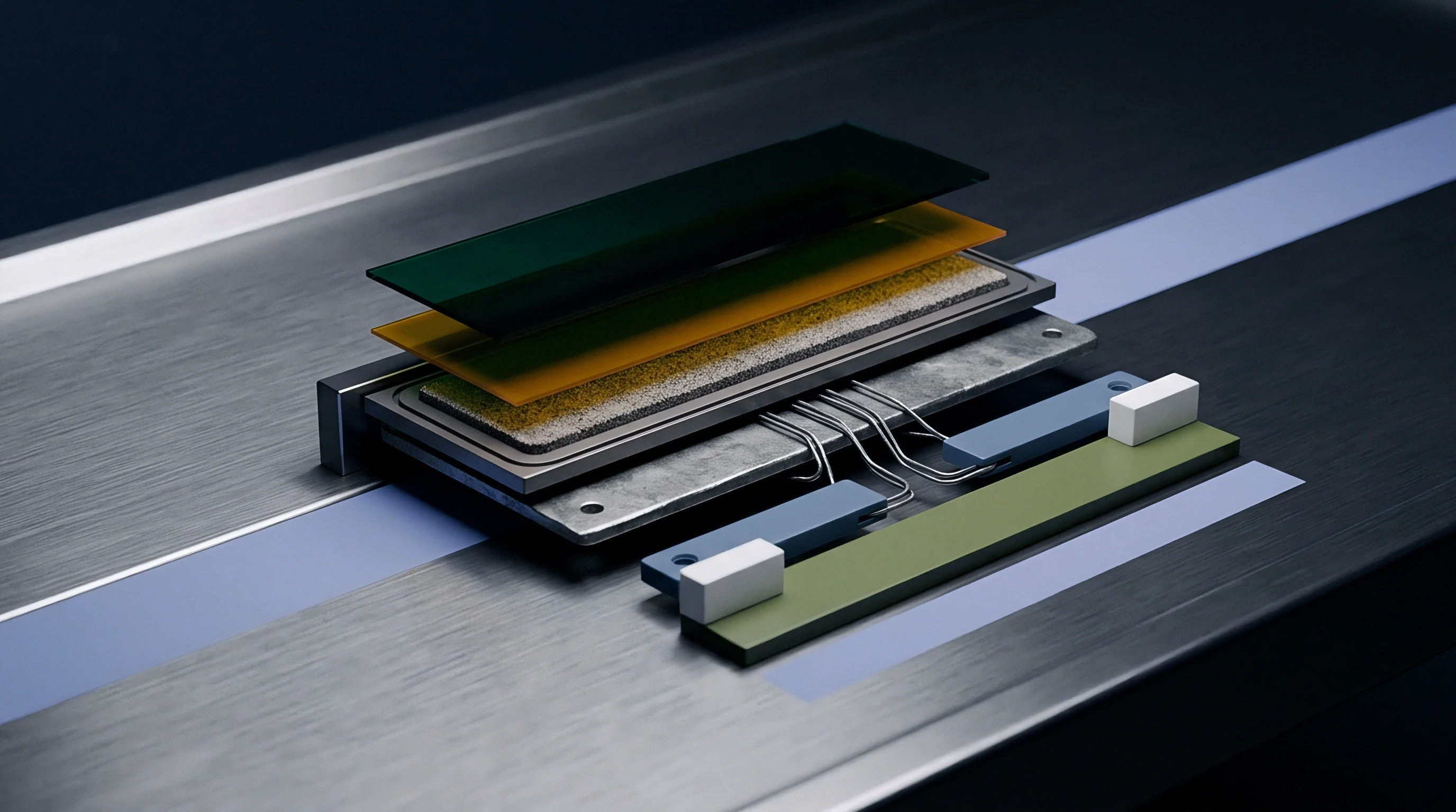
Cyclic expansion of prismatic cell walls induces non-uniform tensile and shear stress distributions across the adhesive interface during every full charge cycle. As the cell pouch or hard casing expands, the central face deforms outward while the constrained welded edges resist displacement. This bowing action forces the structural adhesive directly beneath the center of the cell into heavy compression, while simultaneously placing the adhesive beads located along the outer perimeter into severe tension and peel modes.
Standard engineering test protocols for structural adhesives specified under static load conditions fail to capture micro-void growth initiated by thousands of low-frequency cell expansion breathing cycles.
Over thousands of charge cycles, continuous alternation between compressive loading at the central core and tensile peel along the perimeter drives progressive mechanical fatigue within the polyurethane matrix. Micro-voids coalesce around unbonded thermal filler particles near the outer bead edges. This structural damage reduces the effective load-bearing surface area of the joint, causing a progressive drop in overall structural pack torsional stiffness and creating paths for moisture ingress along the degraded bond line.
| Bondline Nominal Thickness (mm) | Peak Shear Stress Concentration Factor | Bulk Thermal Resistance (K·cm²/W) | Lap Shear Strength at 23°C (MPa) | Fatigue Life (Cycles to Failure at 5 MPa Shear) |
|---|---|---|---|---|
| 0.25 | 3.85 | 1.25 | 17.2 | 120,000 |
| 0.50 | 2.40 | 2.50 | 15.8 | 450,000 |
| 1.00 | 1.45 | 5.00 | 13.5 | 1,800,000 |
| 1.50 | 1.18 | 7.50 | 11.2 | 2,200,000 |
| 2.00 | 1.05 | 10.00 | 8.8 | 1,400,000 |
Controlling bondline thickness represents a major geometric trade-off in cell-to-pack structural design. Ultra-thin bondlines measuring zero point two five millimeters yield low static thermal resistance, yet they generate severe stress concentration factors that dramatically accelerate fatigue failure under cell swelling. Conversely, thick bondlines measuring two point zero millimeters minimize stress concentrations and accommodate large dimensional tolerances of cast trays, but introduce massive thermal impedance penalties and add dead weight to the pack structure.
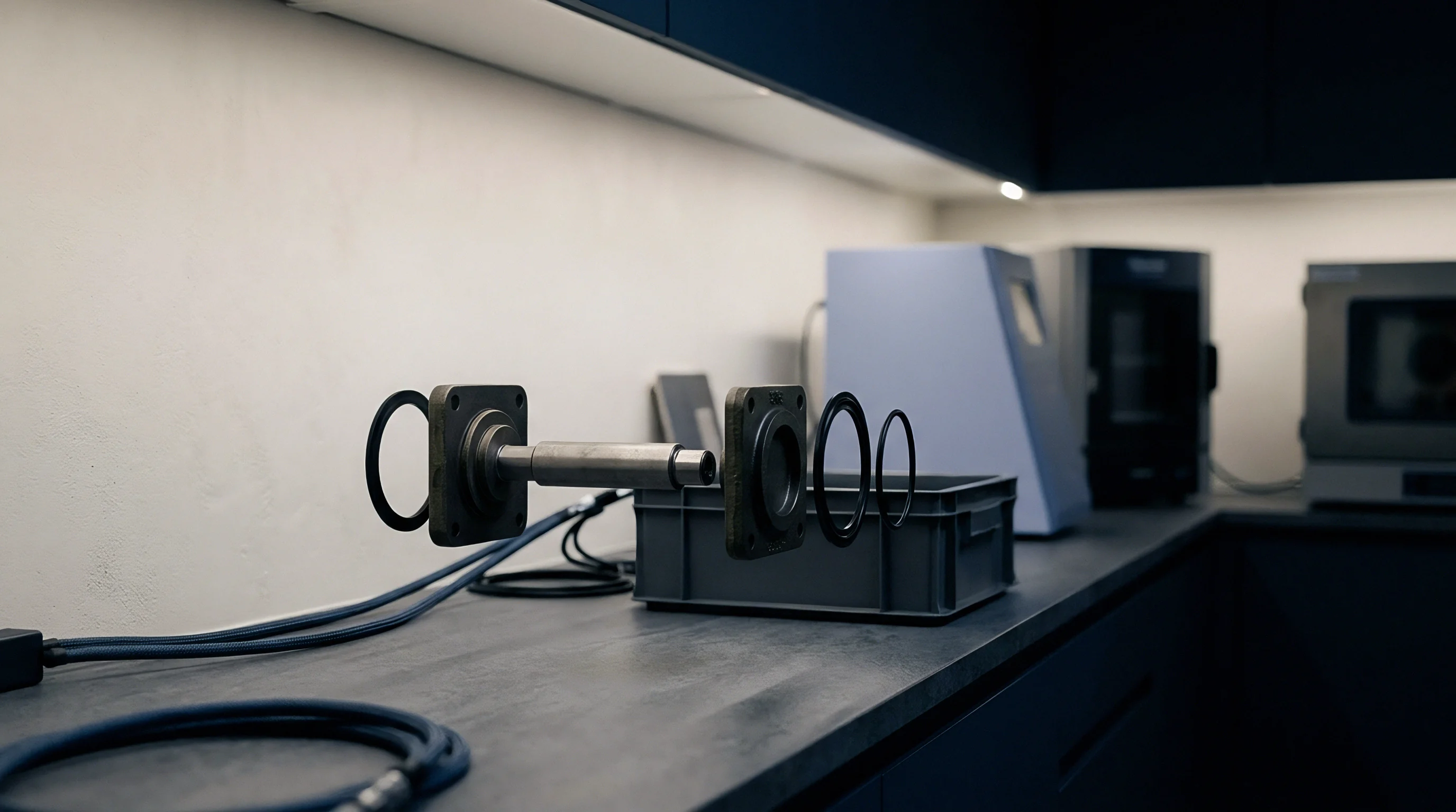
Precision control of the adhesive gap requires integrated glass micro-spheres or high-aspect polymer beads blended directly into the adhesive formulation. Adding zero point seven five millimeter diameter solid glass beads at a concentration of one percent by weight guarantees a hard mechanical stop during cell stack compression. Automated robotic placement heads press the cell stack firmly into the freshly dispensed wet adhesive until the integrated spacer beads contact the aluminum tray floor, securing a precise, uniform bond line thickness across full manufacturing runs.
Bondline Thickness and Creep Resistance
Polyurethane structural adhesives exhibit time-dependent viscoelastic creep deformation under sustained static loading. Inside cell-to-pack architectures, structural adhesive layers experience continuous compressive preload from cell assembly clamping, combined with static shear stresses generated by vehicle mass under spatial gravity loads. Over extended operation at elevated temperatures, the polymer chains slowly realign, yielding permanent plastic deformation of the joint.
Dynamic Mechanical Analysis provides critical baseline creep compliance curves across the target operating temperature spectrum. When ambient temperature inside the battery enclosure approaches sixty-five degrees Celsius during high-power fast charging, the creep rate of filled polyurethane matrices accelerates exponentially. Formulators control high-temperature creep resistance by increasing hard segment concentration and optimizing crosslink density, ensuring structural deflection remains below zero point two millimeters over fifteen years of continuous operation under static load.
Unchecked creep strain alters precisely engineered cell alignments over time.
Compressive creep alters carefully calculated clearances between adjacent cell terminals and internal high-voltage busbars. If the structural adhesive layer beneath a heavy cell stack creeps excessively under continuous vertical acceleration, the physical position of the cells shifts downward relative to the rigid busbar assembly. This dimensional shifting introduces high bending moments and mechanical fatigue stresses into laser-welded copper or aluminum terminal tabs, ultimately driving fatigue cracking of electrical interconnects during vehicle vibration.
- Substrate Dimensional Profiling requires optical laser scanning of the stamped or cast pack tray floor to map local planarity variations prior to adhesive bead dispensing.
- Adaptive Bead Volume Calculation modulates liquid output volume from the dispensing valve in real time based on local tray depth scans to ensure absolute target bondline thickness.
- Controlled Velocity Stack Insertion lowers cell groups into wet adhesive at speeds below fifteen millimeters per second to prevent air pocket entrapment along the bond line.
- Dwell Clamping Hold Sequence maintains continuous pressure on the cell stack until the adhesive reaches green strength to eliminate elastic spring-back movements.
Thermal management through the structural joint requires careful optimization of the interfacial thermal resistance layer. Total thermal impedance of the bonded joint comprises three distinct thermal series resistances: conduction resistance through the bulk aluminum cell casing, conduction resistance through the bulk filled polyurethane layer, and micro-scale contact resistance existing at the dual polymer-metal physical boundaries. Even high-performing filled adhesives present significant bulk thermal resistance compared to pure aluminum metal matrix structures.
Surface roughness on stamped aluminum tray floors traps pockets of non-conductive air when wet adhesive spreads across the surface. At microscopic scales, these air voids create thermal bottlenecks that severely restrict heat dissipation from the cell base into the liquid cooling plate located beneath the tray. Applying dynamic vacuum degassing to adhesive components during fluid mixing and utilizing low-viscosity wet-out formulations eliminates interfacial air entrapment, dropping contact resistance below zero point fifteen Kelvin-centimeters-squared per Watt.
The structural joint design succeeds when the adhesive layer exhibits higher compliance than the bonded metallic substrates while maintaining sufficient shear strength to prevent structural dislocation under maximum chassis impact loads.


Verification
Validating the integrity of structural adhesive bonds within cell-to-pack architectures requires physical destructive testing, accelerated environmental aging, and high-throughput non-destructive inline inspection protocols. Single-lap shear strength tests conducted on pristine laboratory samples at room temperature provide basic quality screening, but fail to predict long-term structural survivability inside aggressive automotive operational environments. Complete testing dossiers must demonstrate mechanical joint survival under multi-axis dynamic fatigue, corrosive chemical exposures, and severe thermal shock conditions.
Standard quality control begins with lap shear testing performed per ISO 4587 or ASTM D1002 standards utilizing aluminum coupons matching the alloy, surface treatment, and coating specifications of actual production cell casings. Mechanical testing frames pull coupons at a constant crosshead displacement speed of one millimeter per minute to record stress-strain curves, peak shear strength, and failure strain energy. Testing must evaluate performance across five critical discrete temperature setpoints: negative forty degrees Celsius, negative ten degrees Celsius, twenty-three degrees Celsius, sixty degrees Celsius, and eighty-five degrees Celsius.

Lap Shear Protocol and Failure Mode Analysis
Analyzing post-test coupon failure surfaces yields diagnostic data regarding chemical bonding mechanisms and process execution quality. Test procedures classify failure modes into five primary physical categories: bulk cohesive failure within the adhesive matrix, adhesive failure at the substrate-polymer interface, thin-layer cohesive failure near the interface, substrate aluminum failure, or coating delamination. Automotive structural sign-off specifications mandate that cohesive failure must cover greater than eighty-five percent of the total bonded surface area across all tested environmental condition windows.
Adhesive failure occurring at the substrate interface indicates poor surface energy preparation, organic surface contamination, or incomplete chemical wetting during bead placement. Thin-layer cohesive failure occurring within fifty micrometers of the aluminum surface points to localized polymer plasticization caused by unreacted moisture layers or incomplete silane coupling reaction kinetics. When test coupons display erratic transitions between cohesive and adhesive failure modes across a single batch, engineers must suspect incomplete static mixing or fluctuating A-to-B component mixing ratios inside the dispensing equipment valve head.
Higher adhesive density directly increases total pack weight.
Dynamic Mechanical Analysis tracks the complex shear modulus and glass transition behavior of cured structural polyurethane samples across a broad temperature frequency sweep. DMA testing subjects cured adhesive specimens to small-amplitude oscillatory shear strain while ramping temperature from negative eighty degrees Celsius to one hundred fifty degrees Celsius at two degrees Celsius per minute. The peak position of the loss factor tan delta curve accurately locates the glass transition temperature, while the storage modulus spectrum demonstrates the material’s load-bearing retention capabilities at elevated operating temperatures.

Environmental Aging and Accelerated Degradation
Long-term environmental durability verification requires exposing bonded lap shear coupons and full-scale sub-assembly mockups to combined thermal and hydrolytic stress environments. The primary environmental stress test consists of continuous eighty-five-eighty-five damp heat exposure, placing specimens inside an environmental chamber held at eighty-five degrees Celsius and eighty-five percent relative humidity for one thousand consecutive hours. Hydrolytic attack targets unreacted soft-segment ester or ether linkages, driving mass gain through water absorption, plasticization of the matrix, and gradual loss of lap shear strength.
Thermal shock testing evaluates structural resistance of the bonded joint to extreme temperature transients caused by rapid environmental shifts and aggressive thermal runaway management events. Specimens undergo one thousand thermal shock cycles between negative forty degrees Celsius and positive eighty-five degrees Celsius, with transfer times between temperature chambers executed within thirty seconds and dwell times maintained for thirty minutes at each extreme. Differential thermal expansion between the high-CTE polyurethane matrix and low-CTE aluminum substrates generates massive localized shear stresses along the bond boundary, exposing micro-cracks and latent interface weaknesses.
ISO 16750-3 section 4.1 mandates continuous random vibration testing across three orthogonal axes while cycling ambient temperatures from negative forty degrees Celsius to positive eighty-five degrees Celsius with operational high-voltage electrical continuity monitoring active.
Chemical resistance validation subjects cured structural adhesive bonds to potential fluid leak scenarios encountered over vehicle lifespans. Test protocols submerge bonded coupons for twenty-four hours in standard automotive fluids, including ethylene glycol-water coolant mixtures, automatic transmission fluid, windshield washer fluid, and electrolyte solvents such as dimethyl carbonate containing lithium hexafluorophosphate. Exposure to lithium battery electrolyte presents an aggressive failure mode: trace moisture reacts with lithium salt to form hydrofluoric acid, which rapidly etches native aluminum oxide layers and causes complete delamination of structural bonds along exposed bead edges within seventy-two hours.
Substrate surface energy determines how effectively the adhesive wets and adheres.

Inline Void Detection and Process Monitoring
Transitioning structural adhesive application into high-volume manufacturing requires automated, non-destructive inline verification systems operating at line takt speeds under sixty seconds per pack. Visual inspection cameras mounted directly on six-axis robotic dispense heads utilize multi-laser line profilometry to measure wet dispense bead geometry in real time. Profilometers track bead height, bead width, cross-sectional area, and bead continuity at five hundred Hertz sampling rates, automatically flagging under-dispensed regions, micro-void gaps, or excessive bead slumping before cell insertion occurs.
Verifying internal void content and contact coverage after cell stack pressing requires advanced non-destructive imaging technology. Active thermography systems apply a brief high-intensity thermal pulse to the outer aluminum pack baseplate using flash lamp arrays or laser sweeps while dynamic mid-wave infrared camera systems record transient surface heat dissipation patterns. Internal voids, delamination zones, and un-bonded areas block heat transfer, creating sharp localized thermal hot spots on the thermal image output that automated image processing software flags against threshold limits.
Purging static mixing nozzles during downtime produces substantial unrecoverable scrap.
High-resolution micro-computed tomography screening on sample production assemblies yields 3D spatial reconstructions of internal bond line geometries, measuring exact internal void size distributions. Production specifications dictate that no single localized void area may exceed five square millimeters, total integrated void area must remain below two percent of the active cell bonding footprint, and minimum bondline thickness must nowhere drop below zero point three millimeters across the entire battery tray layout.
- Line operator retrieves production control test sample coupons from the automated dispense station during shift startup procedures.
- Optical inspection equipment measures uncured wet bead dimensions to verify volumetric dispensing accuracy and bead alignment profile.
- Tensile testing frame performs pneumatic lap shear pull test on fast-cured test coupons, recording failure peak load and mode.
- Data acquisition system automatically uploads measured load curves and cohesive failure percentage data to the factory traceability ledger.
Flame retardancy compliance verification follows strict international safety standards governing electric vehicle pack integrity. Standard UL 94 vertical burning tests require cured five-millimeter-thick polyurethane structural adhesive bars to achieve a UL 94 V-0 rating, demonstrating self-extinguishing behavior within ten seconds of flame removal without releasing flaming liquid droplets. Thermal runaway barrier testing places full-scale structural bonded cell assemblies directly above a localized cell thermal runaway event triggered by nail penetration, requiring the structural adhesive boundary layer to block direct flame penetration for a minimum of twenty minutes while maintaining electrical isolation between the cell group and chassis earth.
Contractual quality annexes stipulate that any delivery lot demonstrating less than eighty-five percent cohesive failure during random destructive lot acceptance testing grants the buyer immediate rights to reject the entire raw material batch and halt line production at the supplier’s expense.

Ledger
Integrating polyurethane structural adhesives directly into cell-to-pack architectures fundamentally alters the landed bill-of-materials cost structure and capital expenditure allocations of electric vehicle assembly lines. Eliminating conventional mechanical module structures, internal aluminum frames, side plates, compression straps, and discrete thermal gap pads removes substantial component count and direct material cost from the battery system. However, this mechanical simplification shifts manufacturing complexity into precision liquid chemical metering equipment, stringent environmental controls, automated inline inspection cells, and direct liability management across supply chain interfaces.
Raw material volumetric landed costs for specialized two-component polyurethane structural adhesives range from eighteen to thirty-four dollars per kilogram depending on thermal conductivity ratings, flame retardancy certifications, and polyol origin. Thermal conductivity performance drives raw material pricing: standard structural polyurethanes rated at one point zero Watts per meter-Kelvin sit at the lower price boundary, whereas advanced formulations packed with specialized spherical alumina achieving two point five Watts per meter-Kelvin command premium pricing due to raw filler processing costs. For a standard one-hundred kilowatt-hour electric passenger vehicle battery pack utilizing an eighty-kilogram structural adhesive dispense volume, raw chemical landed cost represents a direct material commitment of fourteen hundred to twenty-seven hundred dollars per pack.
Metering System Capital Expenditures and Line Takt
Automating two-component structural polyurethane application at volume requires capital expenditure commitments for high-precision meter-mix dispensing equipment. Standard production line installations incorporate dual servo-driven positive displacement gear or piston pumps, temperature-controlled fluid delivery lines, dynamic or static mixer heads, six-axis industrial gantry robots, inline vision profilometry systems, and atmospheric plasma surface treatment cells. A fully automated dual-robot dispensing cell capable of holding sixty-second takt times requires a capital investment between eight hundred thousand and one point five million dollars per line.
Equipment design must handle the abrasive nature of highly filled polyurethane formulations. Standard tool-steel dynamic pump components suffer severe mechanical erosion within fifty thousand dispensing cycles when processing high-alumina formulations, causing continuous volumetric drift and stoichiometric ratio errors. High-volume production lines require specialized tungsten carbide pump gears, ceramic piston sleeves, and diamond-like carbon coated fluid valves.
These wear-resistant upgrades increase initial dispensing skid capital expenditure by thirty-five percent but extend maintenance service intervals from one month out to twelve months of continuous operation.
| Cost & Production Metric | Direct Cell-to-Pack (Polyurethane Bonded) | Traditional Modular Architecture (Gap Filler + Fasteners) |
|---|---|---|
| Direct Material Cost per 100 kWh Pack | $1,450 to $2,400 (Adhesive Only) | $3,100 to $4,600 (Modules, Plates, Pads) |
| Dispense Line Capital Expenditure | $1.2M to $1.8M (Plasma, Robots, Metering) | $450k to $750k (Simple Gap Filler Skid) |
| Production Line Takt Time per Pack | 45 to 75 seconds | 120 to 240 seconds |
| Scrap Financial Exposure per Line Stop | High ($1,800 material purge loss) | Low ($150 gap filler purge loss) |
| Rework & Teardown Financial Liability | Extremely High (Destructive teardown required) | Moderate (Unbolt mechanical modules) |
| Volumetric Mass Efficiency (Cell Mass / Pack Mass) | 65% to 75% | 45% to 55% |
Material scrap during line stoppages represents a significant variable operating cost item. When an automated line halts due to downstream assembly faults, reactive polyurethane material remaining inside static mixing nozzles begins to gel once ambient dwell times exceed the material’s pot life window. Standard five-minute-pot-life formulations require automated chemical flushing procedures or static mixer nozzle ejection cycles every three minutes during unplanned line holds.
Automatic purge cycles consume up to two kilograms of raw material per event, adding thousands of dollars in unrecoverable chemical scrap costs across monthly operational logs.
Responsibility Boundaries across Cell and Pack Interfaces
Transitioning to structural adhesive integration redefines commercial and quality responsibility boundaries between cell suppliers, adhesive formulators, and vehicle pack integrators. In traditional modular pack builds, clear physical boundaries isolate component liability: the cell manufacturer guarantees individual cell performance, the module supplier guarantees structural framework mechanical compliance, and the pack assembler handles final integration. Direct cell-to-pack bonding removes these intermediate structural buffers, creating overlapping liability seams when field structural failures or thermal performance degradation occur.
When an operational pack suffers structural delamination, localized cell overheating, or catastrophic busbar weld fatigue in the field, determining root cause triggers multi-party commercial disputes. The cell manufacturer may blame adhesive surface incompatibility or aggressive mechanical swelling constraints; the adhesive formulator may point to improper plasma surface cleaning, incorrect mix ratios, or improper cure thermal profiles on the assembly floor; the pack integrator faces full vehicle recall costs while arbitrating technical claims between chemical and hardware vendors.
Void size and spatial distribution directly determine dielectric strength across the bond line.
Preventing cross-vendor warranty disputes requires rigorous commercial specification matrices embedded directly into purchase agreements. Contracts must explicitly define substrate surface cleanliness metrics, maximum allowable cell casing swelling tolerances, precise adhesive mixing ratio limits, environmental dispensing window parameters, and required non-destructive testing void detection thresholds. Establishing these quantifiable boundary metrics fixes technical liability on the specific party responsible for any process parameter drift beyond agreed limits.
Unrecoverable yield loss directly increases battery pack manufacturing costs.
Reworking defective cell-to-pack assemblies presents an unresolved financial exposure for structural bonded architectures. If an end-of-line electrical test detects a failed internal BMS sensor connection or a defective cell inside a fully bonded, cured pack tray, disassembling the cured polyurethane joint proves extremely difficult. Unlike bolted modular packs that allow simple unbolting and module replacement, cured polyurethane structural joints require mechanical wire-saw cutting, high-temperature thermal softening, or chemical solvent swelling to remove damaged cells.
- Chemical Batch Certificate of Analysis documents raw polyol hydroxyl numbers, moisture content by Karl Fischer titration, and exact filler loading ratios for every delivered material drum.
- Inline Dispense Data Files store time-stamped robotic bead profilometry scans, dynamic mixing head pressure logs, and ambient dispensing cell temperature and humidity metrics for every pack serial number.
- Plasma Surface Activation Records record surface treatment power outputs, gas flow rates, and robot travel speeds to verify surface energy preparation prior to adhesive contact.
- Destructive Lot Coupon Dossier archives real-time lap shear pull data, glass transition thermal scans, and cohesive failure percentages tied directly to specific manufacturing dates.
Yield recovery procedures must balance component salvage value against repair labor hours and secondary structural damage risk. Chemical swelling solvents capable of breaking down crosslinked polyurethane matrices often attack internal electrical wire insulation, cell pouch seals, and structural composite baseplates, rendering chemical rework infeasible. Most pack integrators write off fully cured defective structural cell-to-pack units as complete scrap, adding a dedicated scrap risk premium of two to four percent onto total pack landed cost models during early manufacturing scale-up phases.
Clear contract terms assign financial risk between chemical suppliers and pack assemblers.
Amortizing long-term warranty reserves requires precise modeling of adhesive degradation profiles against real-world vehicle duty cycles over ten to fifteen year operational lifespans. Standard automotive warranty terms mandate structural battery pack survival over eight years or one hundred fifty thousand kilometers, while emerging commercial transport standards extend durability expectations to fifteen years and one million kilometers. Financial provisions held in reserve for structural interface failures must account for extreme environmental exposures, fatigue accumulation from road inputs, and potential mass-recall actions driven by adhesive batch degradation.
Plasma surface treatment alters surface energy to guarantee long-term joint durability.
Detecting sub-millimeter adhesive micro-voids beneath dense aluminum prismatic casings on high-speed production lines before cure completion remains a critical quality control challenge for non-destructive inline inspection.