Quantifying Interfacial Aging Degradation Dynamics across Variable Thickness Thermal Boundary Layers in Automotive Packs
Variable thermal boundary layers create local cell temperature spreads that accelerate solid electrolyte interphase growth and void supplier warranties.

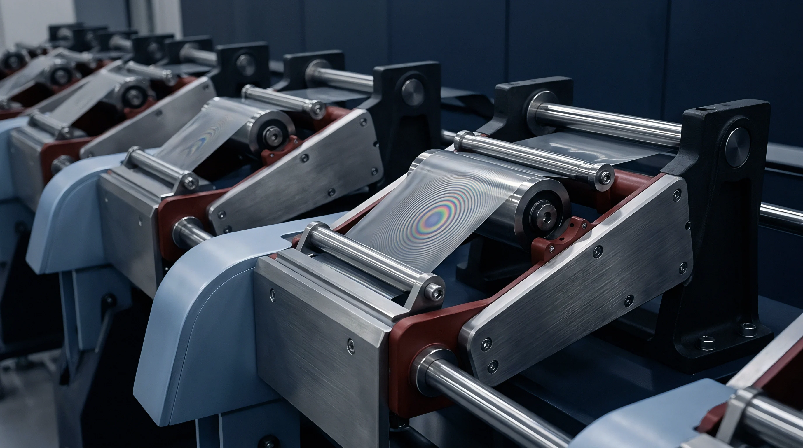
Gradient
Cold plate liquid cooling loops in high-energy automotive battery packs establish localized conduction paths across the bottom or sides of large-format prismatic and pouch cells. Across a 1.5-meter cast or extruded aluminum cooling plate, structural tolerances routinely create gap variances from 0.3 millimeters to 2.2 millimeters against the rigid cell matrix. Thermal interface materials ~ dispensed as liquid gap fillers or laid down as pre-cured pads ~ span this variable boundary layer to maintain heat rejection.
Bulk thermal conductivity for commercial gap fillers generally sits between 1.5 W/m·K and 3.5 W/m·K, compared to 160 W/m·K to 205 W/m·K for aluminum plates. Because conduction resistance scales directly with layer thickness, localized thermal resistance across a single module can swing by up to 400 percent between high-compression center areas and loose perimeter pockets.
This conduction imbalance drives sharp temperature variations across individual cells during DC fast charging and sustained high-power tractive discharge. Even when a cell runs at an average bulk temperature of 25 degrees Celsius, its base can easily range from 28 degrees Celsius above a 0.5-millimeter interface zone up to 38 degrees Celsius over a 2.0-millimeter pocket. Electrochemical kinetics follow these shifts exponentially via the Arrhenius relation.
As a result, solid electrolyte interphase growth, active lithium loss, transition metal dissolution, and graphite particle cracking all proceed at different rates across the footprint of a single jelly roll or wound electrode stack.
Standard automotive qualification testing generally evaluates degradation using pack-average temperature channels, glossing over planar interfacial differentials. Design teams often model the thermal interface material as a single lump-sum resistance in one-dimensional cooling loops. In production, however, wet-dispensed polyurethane and silicone gap fillers are prone to air entrapment, incomplete wet-out, and uneven squeeze-out during module drop-in.
The resulting boundary layer ends up irregular in both thickness and thermal conductivity. That mismatch drives uneven cell aging, localized overpotentials, premature lithium plating in cold areas, and accelerated SEI growth at hot spots.

Thermal Resistance Variance in Structural Battery Enclosures
Tolerance stack-ups in automotive battery trays aggregate variations from extruded cross-members, floor plate flatness, structural adhesive beads, and cell can stamping. High-pressure die-cast aluminum trays show unmachined planar tolerances around plus or minus 1.2 millimeters per meter. Deep-drawn prismatic cell cans add their own base dome variations of plus or minus 0.25 millimeters across the narrow foot dimension.
When eighty to one hundred individual 100 Ah to 200 Ah prismatic cells are torqued down against a shared cooling surface, the actual interface gap varies considerably between adjacent series groups.
Thermal interface materials have to bridge those dimensional gaps. Liquid two-component polyurethanes are typically laid down with uncompressed bead heights of 3.0 to 5.0 millimeters, which collapse to a nominal 0.8 millimeters during module landing. The fluid’s displacement across the plate is controlled by press speed, yield stress, and viscosity.
High squeeze forces can visibly deflect the bottom cooling plate, yielding uneven profiles where center cells rest on tightly compressed 0.4-millimeter films while outer corner cells sit over 1.8-millimeter layers.
| Boundary Layer Configuration | Bondline Thickness (mm) | Interface Thermal Resistance (K·cm²/W) | Cell Base Heat Flux (W/cm²) | Cell Temperature Differential (K) | Local Current Density Variance (%) |
|---|---|---|---|---|---|
| High Compression Center (Liquid Polyurethane) | 0.40 ± 0.05 | 1.33 | 1.85 | 2.4 | +6.2 |
| Nominal Target Zone (Liquid Polyurethane) | 0.85 ± 0.10 | 2.83 | 1.62 | 4.8 | +1.1 |
| Low Compression Pocket (Liquid Polyurethane) | 1.75 ± 0.20 | 5.83 | 1.18 | 9.6 | -8.4 |
| Air Void Defect Region (Entrapped Microvoids) | 2.20 ± 0.35 | 14.60 | 0.54 | 14.2 | -16.7 |
| Pre-cured Silicone Pad (3.0 W/m·K) | 1.50 ± 0.15 | 5.00 | 1.29 | 8.1 | -4.5 |
| Structural Thermally Conductive Adhesive | 0.60 ± 0.08 | 3.00 | 1.58 | 5.1 | +2.3 |
Heat transfer across the thermal interface material depends on effective contact area, bulk conductivity, and surface contact resistance. The combined thermal resistance through the boundary follows standard series conduction:
R_boundary = (t_TIM / k_TIM) + R_contact_plate + R_contact_cell
where t_TIM is local thickness in meters, k_TIM is bulk conductivity in W/m·K, and the contact terms account for surface roughness and microscopic wetting defects at the metal-polymer interfaces. Contact resistance dominates on thin bondlines below 0.2 millimeters, but bulk material conduction takes over once thickness passes 0.6 millimeters. At a 2.0-millimeter thickness with a 1.5 W/m·K filler, conduction resistance climbs to 13.3 K·cm²/W, severely bottlenecking heat extraction from the active jelly roll.
Under continuous fast charging at 2.5C, a 1.2-millimeter increase in thermal boundary layer thickness elevates the steady-state cell core temperature by 7.4 Kelvin.
Different battery form factors manage this boundary in distinct ways. Cylindrical cells arranged upright reject heat through circular bottom cold plates, side-mounted cooling snakes, or combined collector plates. Base cooling on 4680 cells concentrates high heat fluxes through the negative terminal or heavy can base across an area of less than 17 square centimeters per cell.
By contrast, prismatic PHEV2 and VDA cells present broad bottom surfaces between 140 and 300 square centimeters. That large footprint requires much higher fluid dispense volumes, raising the likelihood of entrapping air pockets during automated wet assembly.
Pack structures warp under high mechanical clamping loads during battery assembly. Die-cast trays with shallow stiffening ribs bow downward under module retention bolting, widening the perimeter gap distances. The resulting boundary layer thickness distribution departs from theoretical CAD nominal targets, skewing thermal uniformity across long series strings.
The electrical interconnect design must tolerate these physical shifts while cells experience asymmetric thermal environments throughout their service life.


Shim
Mechanical pack architectures manage stack tolerances through precision metal shims, calibrated gap pads, and closed-loop dispensing systems. The shimming scheme sets the physical reference plane for the cell-to-plate interface. Many production lines now use laser displacement sensors to map cold plate topography before dispensing, allowing the gantry to vary its volumetric flow rate on the fly to match local surface variations.
Machined aluminum shims or molded glass-filled nylon spacers placed at module bolting points provide hard stops during assembly. These prevent over-compressing the thermal material, which could squeeze out the liquid paste until bare contact points cause dielectric breakdown. Sizing these shims requires trading structural support against thermal performance: thicker shims provide reliable electrical clearance under road vibration, while thinner shims lower conduction resistance into the cooling circuit.

Mechanical Stack Tolerances and Rheological Squeeze Mechanics
Squeezing high-viscosity gap fillers between cell cans and aluminum plates builds significant hydrostatic pressure during assembly. Filled polyurethanes behave as Bingham plastics with yield stresses ranging from 150 Pa to 800 Pa. When an automated press pushes a 45-kilogram module down into wet filler beads, fluid resistance pushes back against the cell bottoms. This upward force is highest on center cells, where the paste has to travel furthest to reach open relief channels.
- Substrate surface profiling utilizes high-speed triangulation laser arrays to establish three-dimensional height maps across the entire tray cooling area at a pitch of 1.0 millimeter.
- Adaptive bead trajectory calculation processes point-cloud elevation data to modulate dispensing pump stroke volume across individual module target zones.
- Controlled rate platen compression drives cell module assemblies downward at fixed velocity profiles between 0.2 mm/s and 1.5 mm/s, monitoring instantaneous insertion reaction force to avoid can deformation.
- Optical displacement verification confirms final compressed z-height at four corner locations on each module housing relative to structural tray datum points.
Uneven squeeze dynamics cause density variations and trap microscopic air pockets. When paste viscosity rises ~ whether from cold plant storage or aged material cartridges ~ the paste wets poorly against stamped aluminum. Differences in surface energy between anodized chill plates and polyimide- or PET-wrapped cell cans also shift wetting angles.
Trapped air pockets act as local insulating zones where thermal conductivity drops to 0.026 W/m·K, choking off heat transfer.
Choosing between liquid gap fillers and pre-formed pads involves mechanical trade-offs over life. Pre-cured pads include fiberglass carriers that resist tearing under shear loads. Liquid gap fillers rely on their cross-linked polymer matrices, which can suffer cohesive failure when repeated cell swelling places the bondline in cyclic shear.
As prismatic cells breathe through state-of-charge swings, the interface layer is subjected to continuous mechanical working.
Thermal interface delamination exceeding five percent of active cell base area initiates irreversible localized impedance rise under standard warranty cycle testing.
Swelling forces in constrained modules can reach 15 kN to 45 kN at end of life as graphite and silicon-graphite anodes undergo permanent lattice expansion. That expansion crushes the bottom gap filler over years of use, thinning out the thermal layer. At the same time, module end plates deflect outward, lifting cell corners slightly away from the cold plate.
The boundary layer shifts from center-thick when new to edge-thick at end of life, permanently altering cell thermal maps.
Paste formulations rarely accommodate all tray manufacturing variations without increasing thermal resistance or inducing mechanical can deflection under compression.


Kinetics
Electrochemical reaction rates in lithium-ion cells depend directly on absolute temperature. The rate constant for charge transfer at the electrode-electrolyte interface follows the standard Arrhenius relation:
k_ct = A exp(-E_a / (R T))
where A is the pre-exponential factor, E_a is the activation energy for the specific interfacial process, R is the universal gas constant (8.314 J/mol·K), and T is absolute temperature in Kelvin. Activation energy for charge transfer at the graphite anode sits between 50 kJ/mol and 70 kJ/mol, while lithium-ion desolvation from ethylene carbonate requires around 55 kJ/mol. An 8-Kelvin gradient across a single cell increases local charge-transfer kinetics by roughly 80 percent, setting up substantial current density variations across the electrode plane.
On discharge, current funnels preferentially through warmer sections of the roll because of reduced local charge-transfer and diffusion resistance. That concentration accelerates active material consumption directly over thick, high-resistance thermal interface zones. These warmer sections run at higher effective C-rates than nominal design targets, boosting local Joule heating and establishing a feedback loop that permanently burns through active capacity in patches across the cell.

Where Do Variable Bondlines Accelerate Degradation?
Degradation pathways split based on local operating temperatures across the cell package. In areas resting over thick boundary layers where temperatures run high, side reactions accelerate:
- Solid electrolyte interphase continuous thickening consumes cyclable lithium through solvent reduction reactions, forming inorganic Li2CO3 and LiF species alongside porous organic alkyl carbonates that continuously increase interfacial impedance.
- Transition metal dissolution and migration from nickel-rich NMC cathodes accelerates at elevated temperatures, where trace hydrofluoric acid leaches manganese, cobalt, and nickel ions into the electrolyte to deposit on the negative electrode.
- Active material particle microcracking propagates along primary particle grain boundaries in high-nickel cathodes under localized thermal-mechanical stress, exposing fresh unpassivated surfaces to electrolyte attack.
- Electrolyte salt decomposition via thermal breakdown of LiPF6 into LiF and PF5 gas increases bulk electrolyte viscosity and depletes conductive carrier concentrations throughout the separator matrix.
Over thin boundary layers with direct thermal contact, cell sections stay cold during winter operation or unconditioned fast charging. Low temperatures depress lithium-ion diffusion within graphite particles (D_Li ~ 10^-14 m²/s at 0 degrees Celsius versus 10^-13 m²/s at 25 degrees Celsius). Under fast charging, local anode potential drops below 0.0 V versus Li/Li+, causing metallic lithium to plate onto the graphite surface.
Plated lithium reacts with electrolyte into resistive mossy structures, permanently consuming active lithium inventory and raising safety concerns.
| Interfacial Aging Mechanism | Electrode / Phase Interface | Activation Energy E_a (kJ/mol) | Dominant Operating Regime | Primary Capacity Fade Mode |
|---|---|---|---|---|
| SEI Growth (Solvent Diffusion Limited) | Anode / Electrolyte | 35.0 to 42.0 | High Temp, Elevated SOC | Loss of Lithium Inventory (LLI) |
| Charge Transfer Resistance Growth | Electrode / Electrolyte | 52.0 to 68.0 | All Regimes (Cyclic) | Impedance Rise / Power Fade |
| Lithium Metal Plating Kinetics | Anode Surface / SEI | 12.0 to 18.0 | Low Temp, High C-Rate Charge | LLI / Internal Short Hazard |
| Transition Metal Ion Dissolution | Cathode / Electrolyte | 65.0 to 82.0 | High Temp (>40°C), High Voltage | Loss of Active Material (LAM) |
| Electrolyte Solvent Oxidation | Cathode Surface | 55.0 to 75.0 | High Voltage (>4.2V), High Temp | Gas Generation / Delamination |
Because these degradation mechanisms operate concurrently, a cell over an uneven thermal layer does not age uniformly. One half of the roll loses capacity through SEI growth and particle isolation, while the other experiences lithium plating and rising surface resistance. Standard equivalent circuit and single-particle models overlook this split, masking accelerated aging in fleet telemetry.
Electrochemical impedance spectroscopy spectra evolve distinct bimodal time constants during tests on cells subjected to sustained cross-surface thermal gradients. The high-frequency charge-transfer semicircle broadens and splits into overlapping arcs, reflecting disparate interfacial resistances across the single cell package. Balancing circuits at the pack level cannot equalize these internal gradients, because BMS voltage taps register only the cell-terminal composite potential.
An operating temperature spread of five Kelvin across an electrode plane cuts usable cycle life by twenty percent before reaching warranty retention thresholds.
Operating a pack with heterogeneous interfacial cooling creates localized hotspots that degrade active materials prematurely. Rapid cooling of hot cells cannot overcome the damage generated by persistent localized thermal resistances across variable boundary layers.

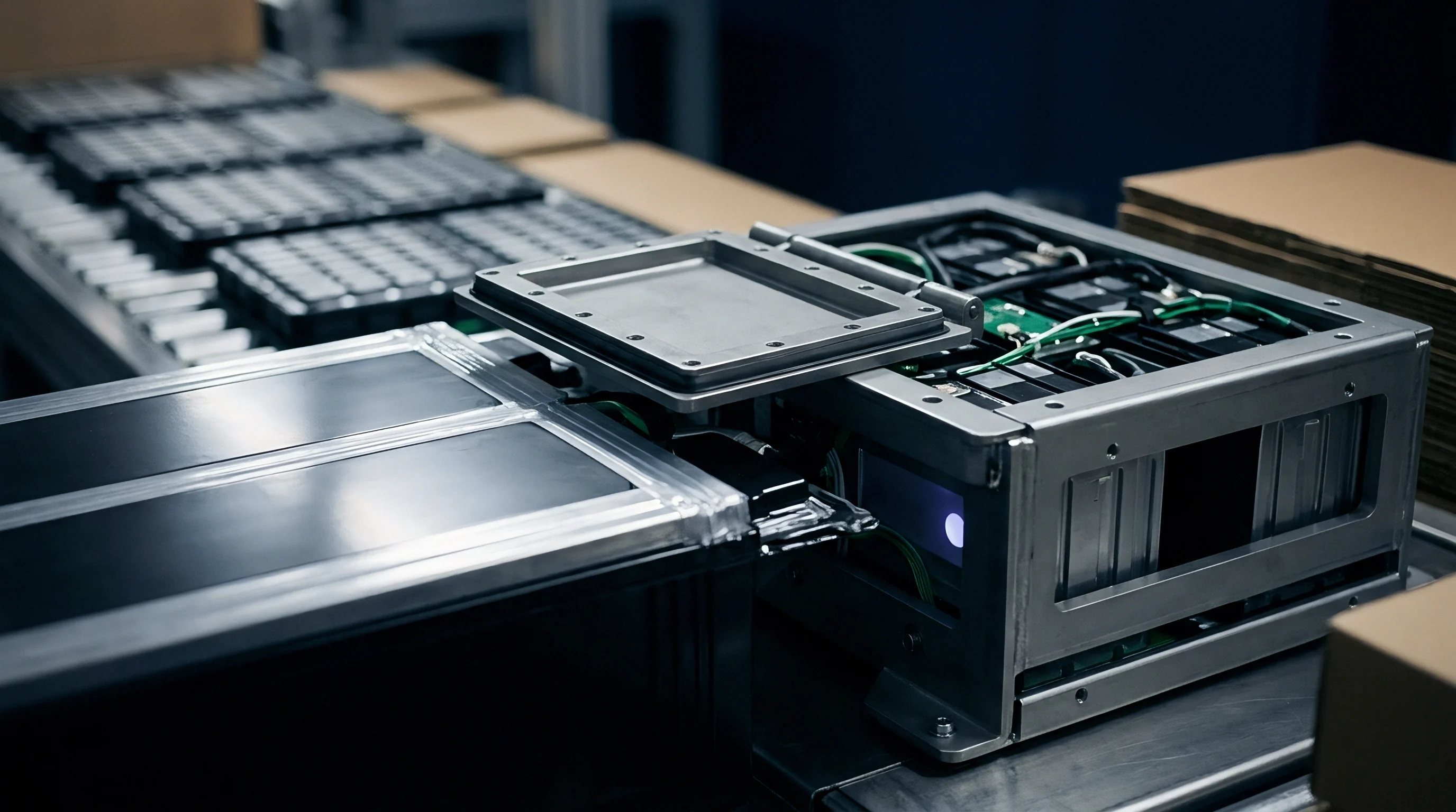
Disparity
Isolating localized degradation caused by boundary layer variations requires separating mechanical stack tolerances from initial cell-to-cell variations. Cells are screened before assembly by open-circuit voltage and 1 kHz AC resistance, holding factory capacity within plus or minus 1.5 percent and AC resistance within plus or minus 3.0 percent. But once mounted over variable thermal interfaces, cell performance diverges well past those initial bands within several hundred cycles.
Coupled thermal-electrochemical finite element models, validated against physical pack teardowns, quantify this divergence. Consider a 12-cell series module constructed with 150 Ah NMC811/Graphite prismatic cells. The structural baseplate features a machined step defect that forces cells 1 through 6 to sit on a 0.5-millimeter polyurethane gap filler layer, while cells 7 through 12 sit on a 1.8-millimeter layer.
Both zones receive identical 25-degree Celsius glycol-water coolant flow along the underside of the aluminum cooling plate.
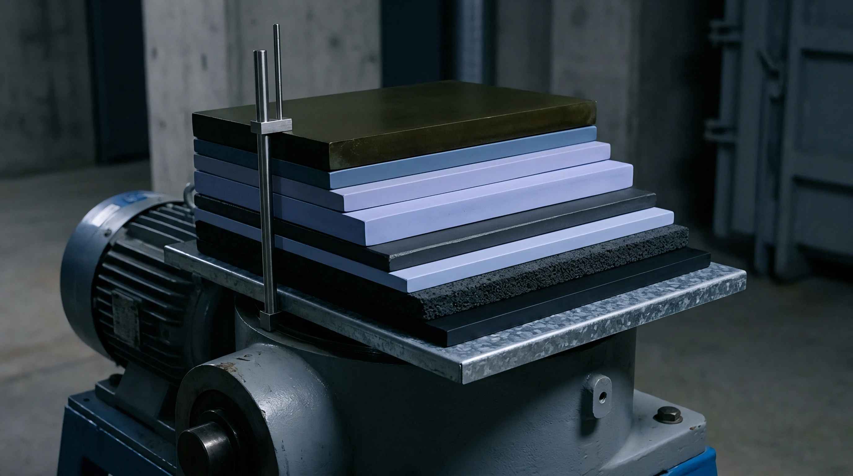
Why Do Bottom Chill Plates Fail Uniformity?
Bottom cooling plates face physical limits because thermal conduction in lithium-ion cells is highly anisotropic. Prismatic cells conduct heat well in-plane (k_xy between 20 W/m·K and 32 W/m·K) along the aluminum and copper current collectors. Across the stack layers (separator, coatings, and electrolyte), through-plane conductivity (k_z) drops to just 0.8 W/m·K to 1.5 W/m·K. Heat generated in the upper section of a 100-millimeter-tall cell must either conduct down the full height of thin foil collectors or cross hundreds of poorly conductive through-plane layers to reach the floor.
| Module Position & Parameter | Zone A (0.5 mm Gap Filler) | Zone B (1.2 mm Gap Filler) | Zone C (2.0 mm Gap Filler) | Maximum In-Pack Disparity |
|---|---|---|---|---|
| Peak Core Temperature during 2C Charge | 31.4 °C | 36.8 °C | 44.2 °C | 12.8 K |
| Base-to-Top Cell Gradient (Vertical) | 4.2 K | 7.8 K | 11.6 K | 7.4 K |
| Capacity Retention after 1,200 Cycles | 88.6 % | 84.1 % | 77.3 % | 11.3 % |
| Direct Current Resistance Increase (DCR @ 50% SOC) | +18.4 % | +29.2 % | +48.6 % | +30.2 % |
| Loss of Active Lithium Inventory (LLI) | 9.8 % | 14.2 % | 21.5 % | 11.7 % |
| Loss of Negative Active Material (LAM_NE) | 3.1 % | 5.8 % | 10.4 % | 7.3 % |
Coupling between local current density, overpotential, and heat generation dictates how quickly interface differences amplify. Total heat output in an electrode segment combines Joule heating, polarization overpotentials, and reversible entropic heat:
q_gen = I (V_ocv – V_terminal) – I T (dU_ocv / dT)
As boundary resistance R_boundary increases, local temperature T climbs. That initial temperature rise lowers charge-transfer overpotential (V_ocv – V_terminal), drawing a larger share of current I_local into the warmer zone until that area is depleted ahead of the rest of the cell. Toward the end of discharge, the depleted active material in the hot zone experiences steep polarization spikes, driving up heat generation right as the discharge cycle wraps up.
Over hundreds of cycles, this uneven loading leaves distinct physical markers. Post-mortem teardowns of cells run over uneven interfaces show pronounced graphite electrode discoloration: areas directly above thick gap filler turn golden-brown from under-lithiation and active lithium loss, while colder areas keep their silver-gray finish alongside localized metallic lithium plating at negative electrode edges.
Unaddressed thermal interface thickness variations skew string capacities, causing battery management systems to trigger low-voltage cutoff limits prematurely based on single degraded units.
Neglecting boundary layer variations leads directly to field capacity divergence, forcing costly early module replacements or premature warranty pack retirements across automotive fleets.


Exposure
Commercial warranty risk for thermal degradation is split across suppliers, material formulators, pack assemblers, and vehicle OEMs. Cell makers typically warrant cell life and capacity curves only under narrow laboratory conditions ~ specifically, isothermal setups where cells are clamped between rigid, temperature-controlled plates held within plus or minus 1.0 Kelvin at 25 degrees Celsius.
Inside a production pack, actual boundary conditions look nothing like those test benches. The pack integrator designs the thermal interface, selects the gap filler chemistry, sources the cooling plates, and runs the dispensing and assembly lines. When irregular boundary layers accelerate cell degradation, cell suppliers routinely deny warranty claims, pointing to out-of-spec temperature gradients across the can.

Commercial Seams, Tooling Investment, and Sourcing Allocations
Deciding how much capital to invest in thermal interface precision means balancing tooling costs against warranty exposure. CNC face-milling of cast cooling plates adds between 12 and 22 dollars per pack, but tightens flatness from plus or minus 1.2 millimeters down to plus or minus 0.15 millimeters. That machining stabilizes gap filler bondlines at 0.50 millimeters plus or minus 0.10 millimeters across the entire pack floor.
- Incoming chill plate flatness metrology measures substrate runout on coordinate measuring machines under simulated pack bolting torque profiles.
- High-pressure dispensing flow calibration balances two-component mixer ratio, dynamic backpressure, and nozzle temperature to prevent void formation during paste deposition.
- In-line laser profilometry inspection verifies wet bead geometry and volume displacement prior to robotic module landing.
- End-of-line transient thermal pulse screening injects calibrated heat pulses into the pack cooling circuit while monitoring cell base thermography to identify sub-surface interface voids.
Choosing a thermal interface material involves balancing raw material cost, line speed, and long-term durability. Low-viscosity silicone gap fillers wet surfaces easily and deliver low contact resistance, but carry risks of siloxane outgassing, which can contaminate high-voltage contactors and optical sensors in sealed enclosures. Polyurethanes avoid outgassing but need higher dispensing pressures and have higher glass transition temperatures, increasing bondline modulus and shear stress in sub-zero conditions.
Wider structural gaps directly inflate material consumption. If a tray designed for a 0.75-millimeter gap ends up averaging 2.0 millimeters in deep pockets, the pack takes roughly 1.8 kilograms of extra filler. At commercial prices of 18 to 35 dollars per kilogram for automotive-grade 3.0 W/m·K pastes, stack-up tolerances translate directly into line-item manufacturing costs.
| Manufacturing & Verification Step | Target Metric and Tolerance Band | Quality Rejection Threshold | Cost of Non-Conformance | Responsible Commercial Entity |
|---|---|---|---|---|
| Cooling Plate Planar Flatness | 0.30 mm / 1000 mm runout | 0.80 mm runout | Plate scrap or secondary CNC milling pass ($18/part) | Tray Stamping / Casting Supplier |
| Gap Filler Dispense Bead Weight | 450 g ± 15 g per module zone | Deviation > 35 g | Purge line, clean substrate, re-dispense ($45/unit) | Pack Assembly Integrator |
| Entrapped Interfacial Void Area | Single void > 15 mm diameter | Module teardown, structural adhesive scrap ($320/mod) | Pack Assembly Integrator | |
| Cell Base Cohesive Bondline Width | 0.70 mm ± 0.15 mm thickness | Thickness > 1.60 mm | Cell degradation warranty claim voiding | OEM Systems Engineering |
| Transient Thermal Step Impedance | ΔT | ΔT > 5.5 K localized | Rework station thermal inspection pull | Joint Pack Sourcing Venture |
Supply contracts need explicit boundary layer validation terms to protect buyers from degradation disputes. Master agreements that omit limits on interfacial thermal resistance across mechanical tolerances leave OEMs carrying the liability for early pack capacity fade. Combining tight metrology, closed-loop dispensing, and clear interface specs keeps thermal boundaries uniform and protects cell life over the vehicle warranty term.
Standard automotive supply agreements require the pack integrator to demonstrate compliance with ISO 16750-4 environmental and thermal profiling clauses across all structural interface tolerances before cell capacity warranties take effect.