Prismatic Cell Cold Plate Thermal Interface Gap Tolerances
Controlling thermal interface gap tolerances down to 0.5 mm prevents local overheating, dry spots, and structural stress in prismatic battery cold plate assemblies.

Topology
Mechanical Stackup Anatomy
Battery pack thermal management relies on continuous physical contact between the metallic bottom casing of hard-case cells and the fluid-cooled aluminum heat sink below. The physical distance between these two surfaces varies across the entire landing area due to manufacturing variations in individual components, assembly positioning deviations, and structural fabrication limits. Calculating this spatial variability requires a rigorous arithmetic stackup model that accounts for bilateral tolerances across every physical layer in the conduction pathway.
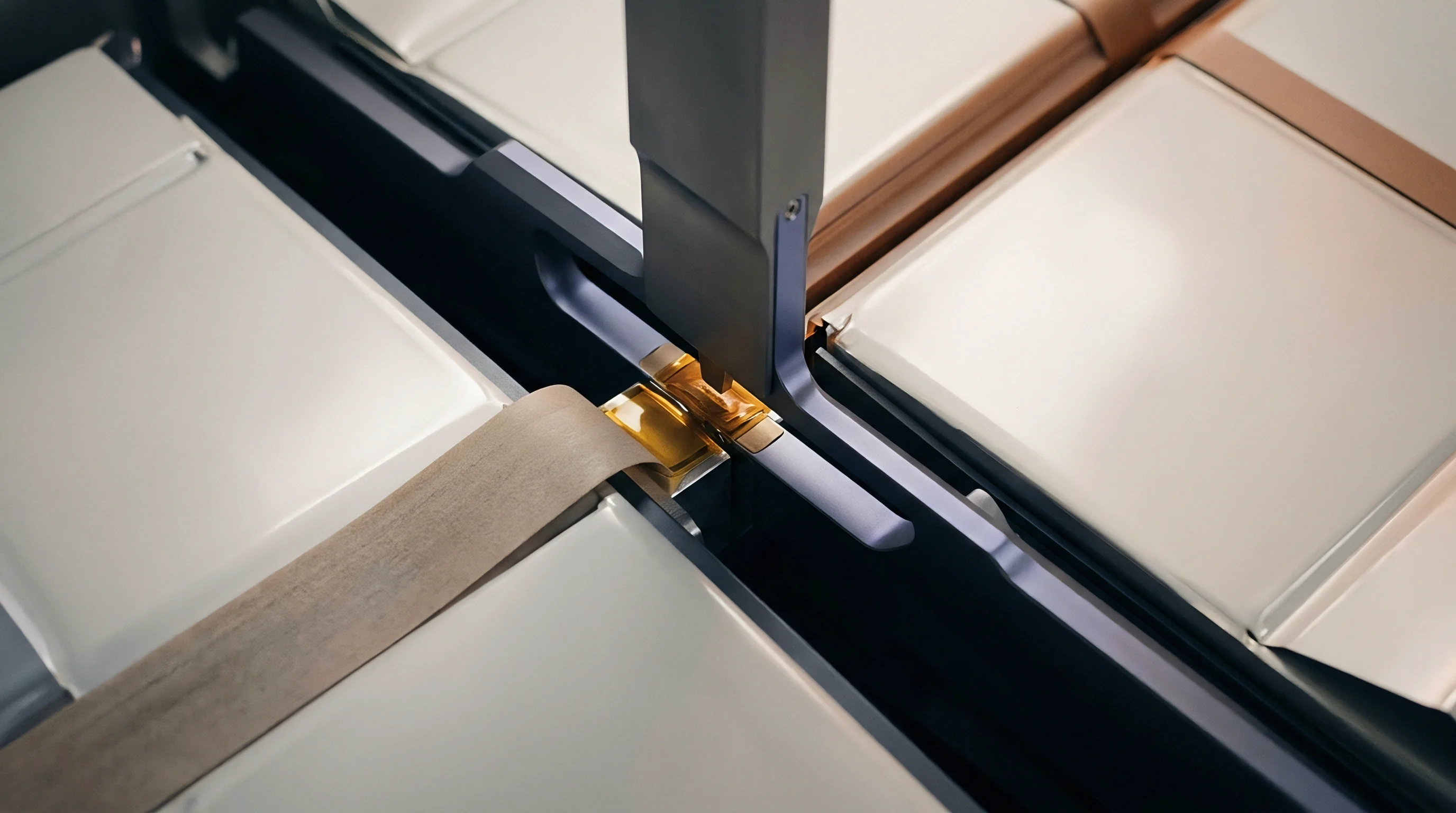
A standard bottom-cooled battery module architecture positions multiple aluminum-sheathed cells directly above a stamped or extruded cooling plate. Between the cell casing and the fluid channel surface sits an electrically insulating dielectric film alongside a dispensable thermal interface material. Each interface layer introduces geometric uncertainty into the total mechanical height budget.
Dielectric isolation films adding 0.10 millimeter to the thermal stackup increase interface thermal resistance by twelve percent when gap filler layer thickness remains uncompressed.
Mechanical drawings specify geometric dimensions alongside their allowable variation limits to bound the minimum and maximum physical gap. When tolerance stackups accumulate unfavorably, the resulting gap either exceeds the maximum wet-out capability of the interface filler or forces structural over-compression during module clamping.
Component Variation Inputs
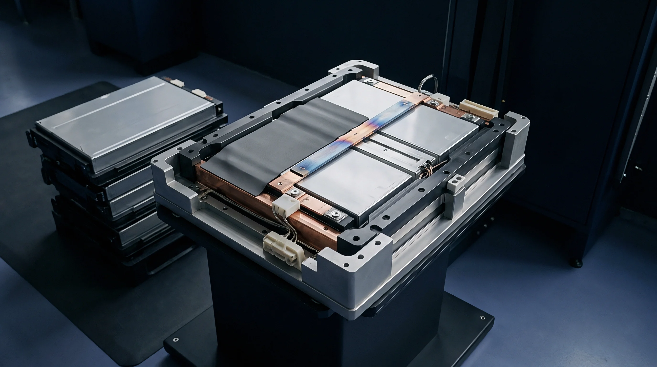
Precision tolerance analysis aggregates individual dimensional variations using both worst-case summation and statistical root-sum-square methodology. Stamping, extruding, machining, and cell manufacturing each contribute distinct statistical distribution profiles to the final stackup outcome.
- Prismatic cell base planarity variation across the long bottom face ranges between positive 0.20 millimeter and negative 0.30 millimeter due to aluminum deep-drawing stress relaxation and internal electrode stack seating.
- Cold plate surface flatness tolerances across extruded aluminum channels typically hold 0.50 millimeter per meter length, with localized surface waviness reaching 0.15 millimeter over any 100-millimeter linear span.
- Structural tray distortion from perimeter welding processes introduces up to 1.50 millimeters of overall chassis bowing across a full battery pack span.
- Dielectric carrier film thickness maintains tight extrusion tolerances of positive or negative 0.015 millimeter, contributing minimal variance relative to structural metal components.
The interaction between these component tolerances determines the local bondline thickness of the liquid gap filler applied during module integration. When cold plate planarity degrades beyond drawing limits, localized gap expansion reduces heat dissipation capabilities and drives thermal runaway risks under high C-rate discharge regimes.
| Component Parameter | Nominal Dimension | Bilateral Tolerance | Manufacturing Method |
|---|---|---|---|
| Cell Base Bowing | 0.00 mm | ± 0.25 mm | Deep Drawn Case Shell |
| Cold Plate Surface Waviness | 0.00 mm | ± 0.15 mm | Extruded Al 6060-T6 |
| Cooling Plate Global Flatness | 0.00 mm | ± 0.50 mm | Friction Stir Welding |
| Insulating PET Film | 0.12 mm | ± 0.015 mm | Precision Roll Coating |
| Target Gap Filler Layer | 0.80 mm | ± 0.45 mm | Automated Automated Dispensing |
Uncontrolled stackup expansion forces integration lines to apply excessively thick interface gel layers, increasing pack mass while elevating thermal resistance across the cooling boundary.
Distortion

Dynamic Geometric Variations during Operation
Static manufacturing variations represent only the initial state of the thermal interface spatial envelope. Once the battery system operates, electrochemical processes and operational heating generate dynamic dimensional shifts that continually alter the local distance between the cell casing and the cooling substrate.
Lithium-ion insertion and extraction within graphite-based anodes drive volumetric expansions of eight to ten percent at the electrode level. Inside a rigid prismatic aluminum casing, this internal volume expansion manifests as external wall bulging, predominantly affecting the broad side faces while altering the curvature of the bottom seating surface.
- Initial cell seating establishes baseline physical contact across the uncompressed thermal gel layer at zero percent state of charge.
- Lithium insertion during charge cycles expands the internal roll stack, pushing the bottom casing downward by 0.12 millimeter near the central axis.
- Continuous micro-cycling induces permanent structural creep within the aluminum shell, permanently shifting the uncharged base profile outward.
- End-of-life electrode degradation and solid electrolyte interphase accumulation generate permanent volumetric swelling up to three percent of initial cell depth.
Thermal expansion mismatches exacerbate these mechanical movements. Aluminum cell casings feature a thermal expansion coefficient of 23 multiplied by 10 to the power of negative 6 per Kelvin, whereas underlying structural frames may expand at different rates under localized thermal gradients.
Structural Plate Deflection
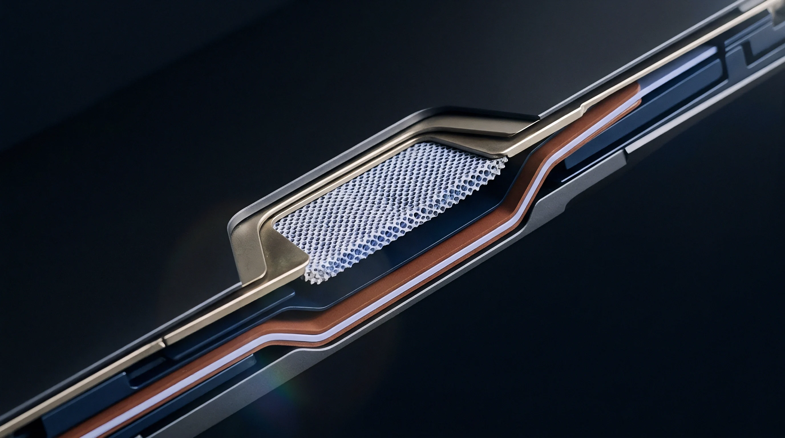
Internal coolant fluid pressure creates mechanical stress within the internal flow passages of liquid cold plates. Stamped aluminum cooling channels flex outward under standard operating pressures ranging from 150 to 350 kilopascals.
This hydraulic bulge pushes the thin top sheet of the cold plate upward toward the cell base, reducing the local gap by 0.10 to 0.30 millimeter along the centerlines of active cooling channels. Under rapid pump pressure fluctuations, this flexing action subjects the cured thermal gel layer to high-frequency mechanical fatigue.
Standard manufacturing specifications allow up to 0.40 millimeter of localized bottom wall convex bowing on pristine prismatic cells before installation.
Cell vendors frequently attribute interface thermal performance failures to structural tray sagging rather than cell casing curvature deviations outside standard inspection windows.


Bond
Thermal Interface Material Compression and Rheology
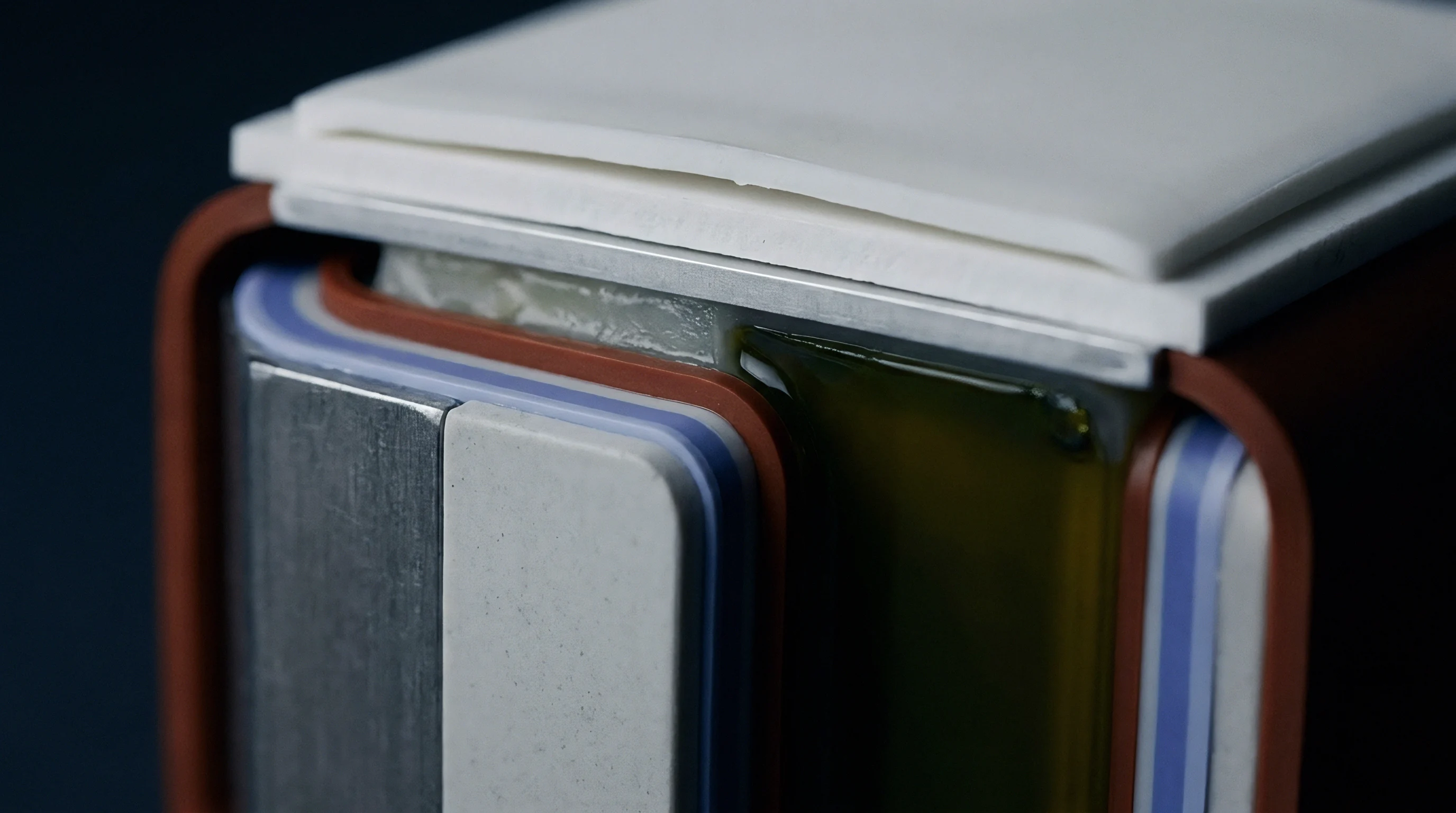
Filling the variable void between cell bases and cold plates requires liquid-applied thermal interface materials that deform easily under low mounting pressures. These gap fillers consist of silicone or polyurethane polymer matrices heavily loaded with thermally conductive ceramic particles such as alumina or aluminum nitride.
How Does Gap Variation Alter Dispense Force?
Automated dispensing systems apply fluid gap fillers in continuous beads or engineered patterns across the cooling plate prior to cell placement. As the module assembly tool lowers prismatic cells onto the wet interface gel, the fluid squeezes laterally to cover the entire contact footprint.
Rheological behavior dictates how the material flows under applied mechanical load. High yield-stress materials resist initial displacement, demanding elevated mounting forces to achieve thin bondline targets. Excessive compression forces risk damaging internal cell jelly rolls or crushing delicate cooling channel walls.
In regions where mechanical stackups produce a wide spatial gap, the fluid filler must maintain contact without slump or phase separation. Conversely, narrow gap areas subject the filler to high shear rates, potentially breaking down polymer cross-links or driving fluid out of the contact zone entirely.
- Yield stress threshold dictates the minimum compression force needed to initiate lateral gel flow across stamped aluminum surfaces.
- Thixotropic index values govern material recovery time after dispensing to prevent bead sagging before cell positioning occurs.
- Minimum bondline thickness limits prevent ceramic filler particle crushing, which otherwise creates local stress concentration points on cell bottoms.
- Volumetric compression ratio defines how much trapped air escapes during cell seating without leaving permanent internal air pockets.
Extensive void formation inside cured gap fillers creates insulating air pockets with thermal conductivities near 0.026 Watt per meter-Kelvin. These local dry spots restrict heat flow, generating localized thermal hot spots during fast-charging operations.
Dispensing excess gap filler volume guarantees complete surface wet-out across maximum gap conditions while squeezing surplus material into designated compression squeeze-out channels.

Resistance

Thermal Impedance Modeling across Variable Gaps
Heat transfer through the bottom boundary layer follows Fourier’s law of thermal conduction. Total thermal impedance across the interface combines the bulk conduction resistance of the interface material with the contact resistances present at both metal-to-polymer boundaries.
Calculating the total temperature drop between the internal cell junction and the circulating liquid coolant requires summing individual conductive layers. Bulk thermal resistance scales linearly with bondline thickness, making gap control the primary variable governing thermal performance.
| Bondline Thickness (BLT) | TIM Conductivity | Void Content | Thermal Resistance | Temperature Delta at 50W Heat Load |
|---|---|---|---|---|
| 0.30 mm | 3.0 W/m·K | 0% | 0.10 K·cm²/W | 1.25 K |
| 0.75 mm | 3.0 W/m·K | 0% | 0.25 K·cm²/W | 3.12 K |
| 1.50 mm | 3.0 W/m·K | 0% | 0.50 K·cm²/W | 6.25 K |
| 1.50 mm | 3.0 W/m·K | 15% | 0.68 K·cm²/W | 8.50 K |
| 2.00 mm | 3.0 W/m·K | 25% | 1.05 K·cm²/W | 13.12 K |
Doubling the interface thickness from 0.75 millimeter to 1.50 millimeters increases the conductive thermal resistance by 100 percent when material properties remain constant. Under a representative 50-Watt heat load per cell during fast charging, this resistance increase drives a 3.13 Kelvin elevation in baseline cell operating temperature.
Consider an assembly scenario with a 2.0-Watt per meter-Kelvin gap filler specified across a nominal 1.0-millimeter gap. Assume mechanical tolerance stackup analysis yields a minimum gap of 0.40 millimeter and a maximum gap of 1.60 millimeters across a module array.
At the minimum gap location, bulk conductive resistance drops to 0.20 Kelvin-square-centimeter per Watt, providing efficient heat transfer but increasing mechanical compression stress on the cold plate. At the maximum gap location, bulk conductive resistance jumps to 0.80 Kelvin-square-centimeter per Watt.
This four-fold variation in localized thermal resistance across neighboring cells within the same electrical string creates severe thermal imbalance. Cells situated over wider gaps run consistently hotter, accelerating capacity degradation rates and shortening the total usable lifecycle of the battery pack.
ISO 16750-3 vibration testing verifies that cured thermal gap fillers maintain physical adhesion across thermal expansion cycles without delaminating from aluminum casings.
Whether mechanical vibration combined with differential thermal expansion causes micro-cracking inside ultra-thin bondlines over 3000 thermal cycles remains an open area of engineering evaluation.

Acceptance
Quality Control and Production Inspection
Controlling thermal gap variations on fast-takt manufacturing lines demands rigorous inline measurement systems alongside tightly specified procurement documents. Relying on final end-of-line thermal imaging fails to catch localized interface defects before structural adhesive curing occurs.
Laser triangulation sensors and 3D optical profilometers scan cooling plate topographies immediately before liquid gap filler application. These automated inspection stations map surface waviness and calculate exact volume requirements for localized dispense patterns, dynamically compensating for plate distortion.
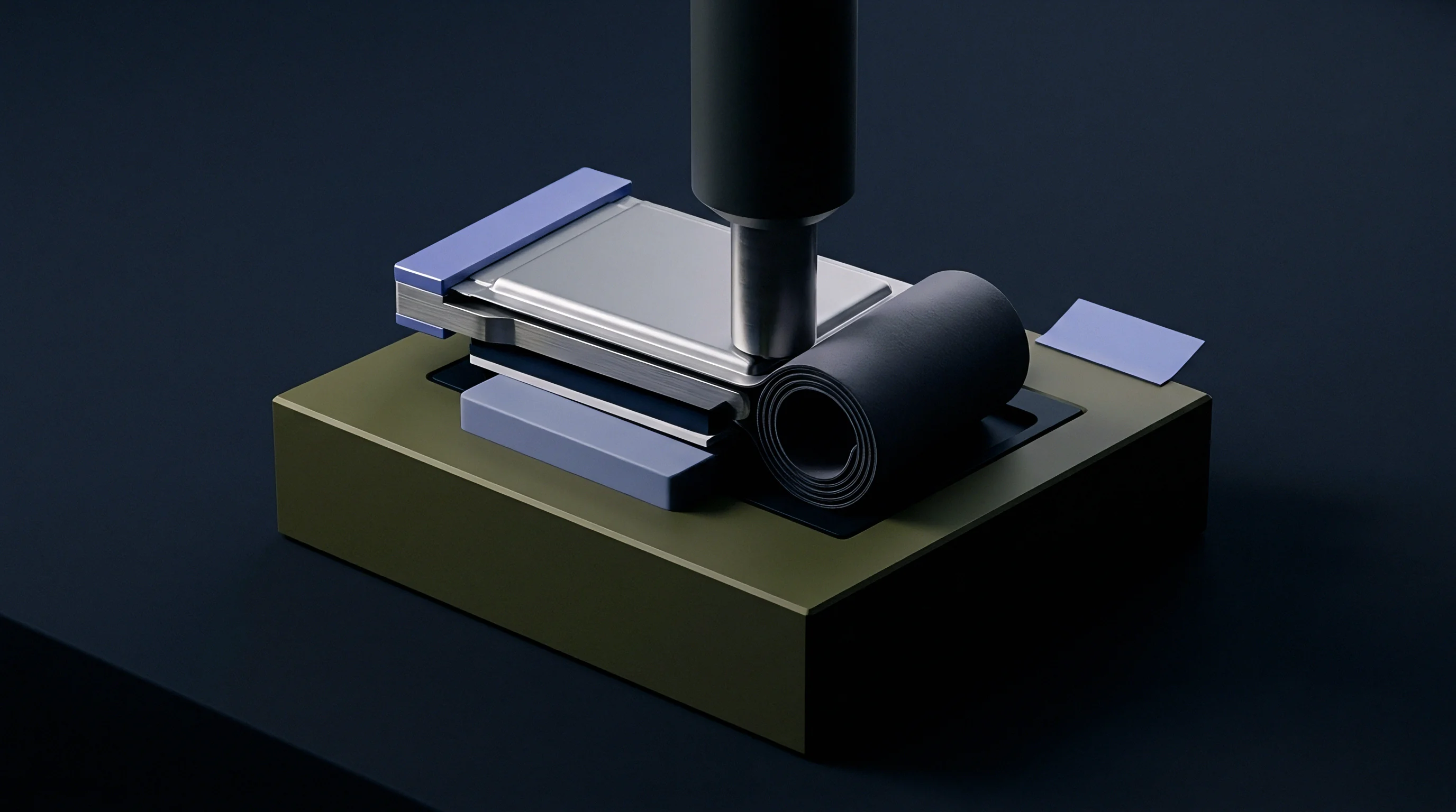
Following cell positioning, automated force-displacement monitoring on the module assembly press verifies proper seating height. Compression force curves that deviate from calibrated thresholds signal either insufficient gel volume, pre-cured material, or physical obstruction from foreign object debris.
- Profilometer scan resolution must capture surface height points at intervals no greater than 1.0 millimeter across the entire cell seating zone.
- Dynamic dispense controls adjust automated syringe flow rates in real-time based on upstream optical height map inputs.
- Ultrasonic acoustic imaging audits cured bondline thickness and detects internal air voids down to 0.50 millimeter diameter without destructive disassembly.
- Interface shear testing verifies long-term adhesion retention on sample coupon assemblies subjected to temperature cycling between negative 40 and positive 85 degrees Celsius.
Engineering drawings specify non-uniform gap tolerances by explicitly detailing maximum allowable local spatial variation alongside total volume limits for the squeezed interface layer.
Contractual supply agreements mandate that cell cases adhere to geometric tolerance callouts defined under standard DIN 7168 medium class, transferring financial liability for thermal interface dry spots to cell manufacturers when base concavity exceeds 0.30 millimeter.