Thermal Interface Selection Criteria for Prismatic Battery Modules
Optimal prismatic module thermal interface selection balances bulk conductivity against rheology and compliance to accommodate swelling without dielectric rupture.


Gap
Heat conduction between a prismatic cell bottom and a liquid cold plate depends on complete surface mating across the joint. Microscopic surface irregularities and macroscopic tolerance stack-ups create interstitial voids across the contact boundary. Air pockets act as thermal insulators; unfilled air gaps exhibit a bulk thermal conductivity of approximately 0.026 W/m·K, imposing a severe thermal barrier between heat-generating active material and the cooling system.
Eliminating these pockets requires an interface material capable of conforming to dimensional variations under nominal clamping pressure.
Dimensional stack-up analysis across prismatic battery assemblies reveals multiple geometric tolerances that influence joint thickness. Cell cans manufactured from deep-drawn 3003 aluminum alloy possess inherent side-wall bowing, base doming, and edge radius variations. Cold plate extrusions and friction-stir welded cooling structures exhibit surface planarity tolerances, heat-sink twist, and local weld bead high points.
When multiple cells line up inside a module housing, cumulative deviations produce interface separation gaps ranging from 0.2 mm to over 1.5 mm across a single cooling plane.
A 100-micrometer air pocket within a thermal interface layer increases localized thermal resistance by more than 350 K-mm²/W.
Thermal Contact Resistance Mechanics
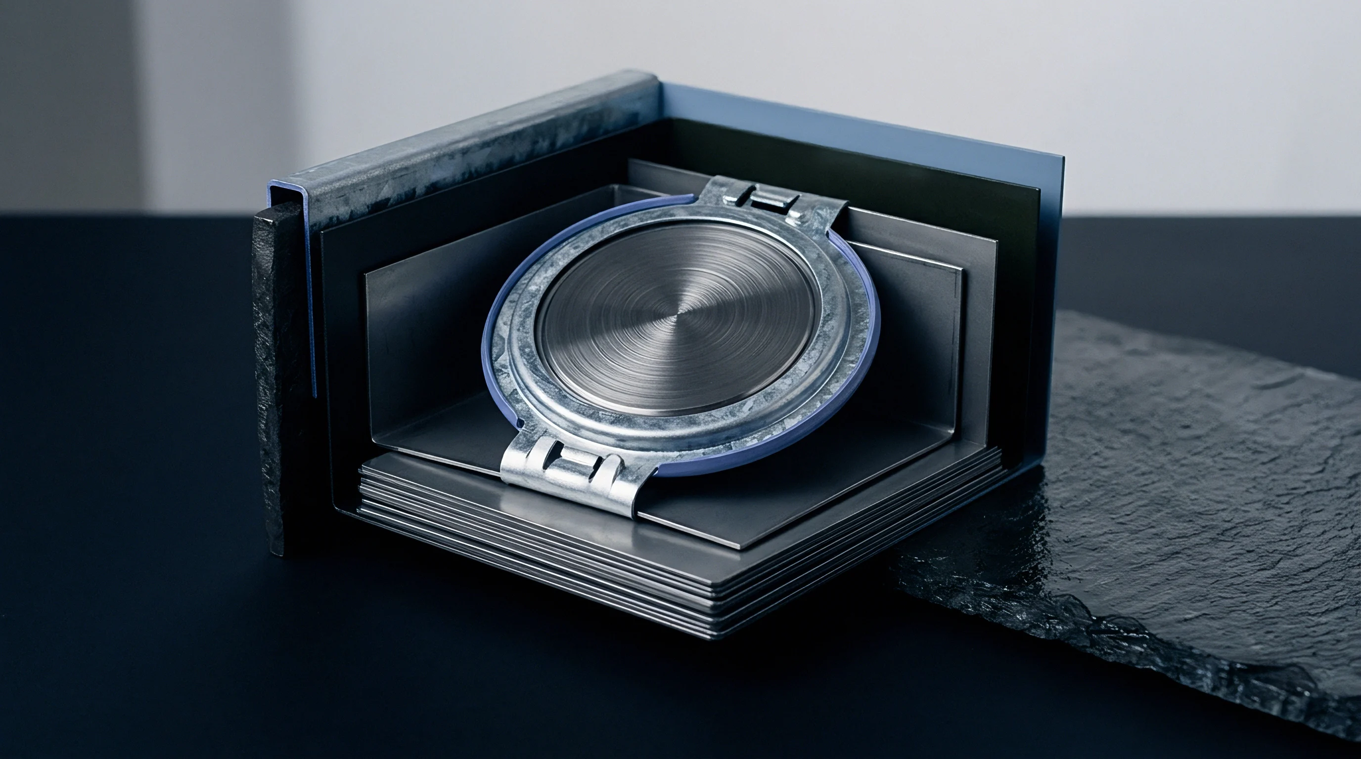
Energy transport across solid material boundaries encounters microscopic non-uniformities that disrupt direct conduction pathways. Thermal contact resistance consists of two components acting in series: the bulk thermal resistance of the interface material itself and the contact resistance at the two mating interfaces. Total thermal resistance per unit area follows a linear relationship with material thickness.
Bulk resistance equals material thickness divided by bulk thermal conductivity. Interface contact resistance depends on surface roughness, clamping pressure, and how effectively the material wets the substrate. High bulk conductivity provides little operational benefit if high surface stiffness prevents complete wetting under available assembly forces.

Planarity Variations across Modules
Manufacturing tolerances in aluminum prismatic enclosures introduce significant dimensional deviations along the bottom surface. Formation cycling during cell manufacturing induces internal gas pressure, causing side-wall deflection and bottom planarity distortion. A cell bottom that bulges outward along its central axis creates an uneven gap profile when pressed against a flat cooling surface.
Bond line variations alter heat transfer rates. The thermal management architecture must compensate for maximum material condition stack-ups where the gap narrows, alongside minimum material condition stack-ups where the gap widens. A module design specifying a nominal 0.5 mm thermal interface layer routinely experiences localized compression down to 0.15 mm under cell high points and expansion up to 1.10 mm over cell low points.
| Prismatic Form Factor | Nominal Base Dimensions (mm) | Bottom Planarity Tolerance (mm) | Design Bond Line Range (mm) | Interface Resistance at Nominal BLT (K·cm²/W) |
|---|---|---|---|---|
| VDA PHEV2 | 148 x 26 | ±0.15 | 0.20 to 0.60 | 0.85 |
| BEV Medium (200Ah) | 173 x 45 | ±0.25 | 0.30 to 0.80 | 1.12 |
| BEV Large (302Ah) | 173 x 72 | ±0.35 | 0.40 to 1.20 | 1.58 |
| High-Capacity Extended | 220 x 79 | ±0.45 | 0.50 to 1.50 | 2.05 |
To evaluate the thermal impact of thickness variation across a module, take a 302 Ah LFP prismatic cell operating under a continuous 1C discharge rate (302 A). Internal electrochemical impedance generates 28 W of heat dissipation per cell. The base area measures 173 mm by 72 mm, yielding a contact area of 0.01245 m².
A thermal interface material with a bulk thermal conductivity of 3.0 W/m·K and an interfacial contact resistance of 0.20 K·cm²/W exhibits the following thermal behavior across the stack-up tolerance band:
Under nominal bond line thickness (0.50 mm), bulk thermal resistance equals 1.67 K·cm²/W. Total resistance per unit area, including both contact surfaces, reaches 1.87 K·cm²/W (0.000187 K·m²/W). The total thermal resistance across the cell footprint equals 0.0150 K/W. Multiplying heat generation (28 W) by thermal resistance yields a temperature drop across the thermal interface layer of 0.42 °C.
Under maximum gap condition (1.20 mm bond line thickness due to cell and cold plate tolerance stack), bulk thermal resistance increases to 4.00 K·cm²/W. Combined interface resistance reaches 4.20 K·cm²/W (0.000420 K·m²/W). Thermal resistance across the cell area rises to 0.0337 K/W. The resulting temperature drop across the thermal layer expands to 0.94 °C. If localized entrapment creates a 5% air void fraction under this maximum thickness condition, local thermal resistance spikes, increasing the localized temperature delta to 2.15 °C.
Ignoring bottom face planarity tolerances creates localized thermal hotspots that accelerate cell degradation and trigger localized thermal runaway during high-discharge pulses.


Rheology
Flow properties of liquid interface materials dictate how easily a compound spreads under assembly force to coat mating surfaces. Yield stress, thixotropic behavior, and shear-rate viscosity curves govern liquid gap filler performance during automated high-speed dispensing and cell insertion. A material with incorrect rheological behavior either bleeds out of the joint before curing or resists compression, transferring excessive mechanical stress to cell structures.
Yield stress represents the minimum force required to initiate material flow. High yield stress prevents liquid gap fillers from slumping or running off inclined cold plate surfaces prior to module assembly. Once applied force exceeds yield stress, shear-thinning behavior reduces effective viscosity, allowing the compound to spread smoothly into tight gaps under moderate compression forces.

Viscoelastic Behaviour under Pressure
Polymeric interface compounds exhibit combined liquid and solid mechanical responses under sustained structural clamping. Elastic responses store mechanical energy, while viscous responses dissipate energy through flow. During initial assembly squeeze, high viscous flow allows the material to fill surface roughness and geometric gaps.
Post-cure elasticity maintains contact force against surfaces over thermal cycling.
Viscosity drops under continuous shear forces. Non-Newtonian gap filler formulations must balance filler loading with polymer resin chain length. Spherical aluminum oxide particles provide high thermal conductivity but increase viscosity and abrasive wear on dispensing pumps.
Platelet boron nitride particles yield higher conductivity at lower loading levels but induce anisotropic thermal pathways if shear alignment occurs during dispensing.

Comparing Pad and Liquid Chemistries
Pre-formed elastomeric sheets deliver uniform thickness across flat mating planes without requiring automated mixing equipment. Pre-cured pads require higher placement pressure. High compression forces needed to compress thick elastomeric pads can deform thin-walled cooling plate channels or bend module end plates during assembly.
Liquid gap fillers flow easily into irregular volumes, achieving thin bond lines with low insertion force. Two-part room-temperature vulcanizing silicones, polyurethanes, and epoxies cure in place to form custom thermal joints. Liquid gap fillers eliminate high static compression preloads, protecting delicate cell structures during battery pack manufacturing.
| Material Class | Bulk Conductivity Range (W/m·K) | Viscosity / Hardness Range | Minimum Assembly Pressure (kPa) | Reworkability Index |
|---|---|---|---|---|
| 1-Part Silicone Gel | 1.5 – 3.5 | 150,000 – 400,000 mPa·s | 20 – 50 | High |
| 2-Part Polyurethane Liquid | 2.0 – 4.5 | 50,000 – 200,000 mPa·s | 30 – 100 | Moderate |
| Pre-Cured Silicone Pad | 1.0 – 6.0 | 20 – 70 Shore OO | 150 – 500 | High |
| Acrylic Phase-Change Sheet | 3.0 – 8.0 | Phase change at 45 – 55 °C | 100 – 300 | Low |
- Pump-out degradation occurs when differential thermal expansion between cell base aluminum and cold plate metal drives cured soft gels out of the joint during power cycling.
- Silicone oil migration releases low-molecular-weight siloxane volatiles that condense on electrical contacts, forming insulating silicone dioxide deposits under high-voltage arcing.
- Filler settling separation happens during liquid transport or reservoir storage when heavy mineral thermal fillers drop out of lower-viscosity carrier resins.
- Mechanical shear tearing ruptures low-elongation gap pads when side-to-side cell expansion generates lateral displacement forces along the cooling interface plane.
Minor filler settling during transit does not alter bulk thermal performance once the compound passes through high-shear static mixers.


Strain
Lithium-ion intercalation into graphite anodes drives periodic volume changes inside sealed prismatic cell enclosures. Reversible expansion occurs during every charge cycle, expanding the cell thickness axis. Irreversible swelling accumulates over operational life due to solid electrolyte interphase layer growth, internal gas generation, and structural electrode degradation.
The thermal interface material layer sits directly within this dynamic mechanical load path.
Prismatic cans swell during charge cycles. As the cell thickness dimension expands against rigid module endplates, internal stack pressure rises. The bottom cooling interface experiences intense cyclic compressive loads and lateral shear stresses.
Thermal interface materials must absorb cyclic mechanical displacement without cracking, delaminating from aluminum surfaces, or increasing thermal contact resistance over thousands of charge-discharge cycles.

Cell Breathing and Cyclic Expansion
Prismatic battery housings experience dynamic physical swelling during charge and discharge sequences. Fresh cell charge-discharge breathing induces a 1.0% to 2.5% variation in cell thickness. End-of-life cumulative expansion can exceed 8.0% of nominal cell thickness if module constraints allow displacement.
Anode expansion drives internal pressure up.
Module designs incorporate compressive foam spacers between adjacent cell side walls to absorb cell breathing. Expansion along the bottom plane transfers directly into the thermal interface layer. If the interface layer lacks sufficient compliance, cyclical compression drives progressive thinning under high pressure zones, forcing liquid materials out from under the cell base.
Flexible thermal interface materials accommodate cell expansion without transmitting structural peak loads to the cooling plate headers.

Mechanical Stress Mitigation
Structural loads originating from swollen prismatic cans transfer directly into module endplates and underlying thermal structures. Rigid epoxy gap fillers lock the cell bottom to the cold plate, creating a rigid structural assembly. When the cell expands, shear strain concentrates along the bond line.
Epoxies with high tensile modulus transfer high stress into cold plate weld joints, potentially causing coolant leaks or cell casing damage.
Viscoelastic interface compounds mitigate stress by flowing slowly under long-term loads while maintaining elastic resilience against short-term vibrational inputs. Low-modulus polyurethanes and soft silicone elastomers deform elastically under cyclic breathing loads, limiting peak force transmission to cooling plate structures. Rigid fillers crack under cyclic compression.
To quantify stress transmission and bond line thinning over module life, consider a module array containing 12 prismatic cells mounted to a common aluminum cooling plate. Each cell exhibits a nominal base width of 173 mm and a thickness of 72 mm. Fresh cell installation applies a baseline pre-charge clamp force that exerts 200 kPa pressure on the 0.80 mm thick thermal gap filler layer (bulk modulus E = 4.5 MPa, shear modulus G = 1.5 MPa).
During maximum charge state at 80% state-of-health (end-of-life), cell swelling forces generate a vertical cell expansion displacement of 0.18 mm toward the cold plate at the base center, combined with a 0.25 mm outward lateral shear displacement at the cell edges due to thermal and swell expansion. The compression strain on the gap filler directly under the central bulge equals 0.18 mm divided by 0.80 mm, or 22.5% compressive strain.
Vertical normal stress generated in the gap filler under this strain equals compressive strain multiplied by bulk modulus: 0.225 × 4.5 MPa = 1.0125 MPa (1,012.5 kPa). This represents a five-fold increase over initial baseline assembly pressure. Simultaneously, lateral shear strain at the cell edge equals 0.25 mm divided by the reduced gap thickness (0.62 mm), yielding a shear strain of 40.3%.
Interface shear stress equals shear strain multiplied by shear modulus: 0.403 × 1.5 MPa = 0.605 MPa (605 kPa).
If the selected gap filler exhibits high viscoelastic compression set exceeding 30% under sustained elevated temperature (60 °C), sustained high pressure drives permanent material displacement outward. When the cell subsequently discharges and cools, contracting back toward initial dimensions, the gap filler fails to recover its original thickness. The permanent set leaves an uncompressed interfacial void gap of 0.054 mm, increasing interfacial thermal contact resistance by 180% during low-SoC operational states.
Under ISO 12405-4 section 8.3, failure to accommodate 15 percent cyclic thickness variation invalidates module structural integrity certification and reassigns mechanical failure liability to the pack integrator.


Dispensing
Automated liquid application systems transfer precise volumes of thermal gel onto cold plate landing zones. Manufacturing line integration requires strict control over volumetric dispensing flow rates, material viscosity, pump pressures, and robot travel speed. Deviations in material dosing result in dry spots that overheat cells or excess material overflow that contaminates high-voltage electrical connections.
Two-part thermal gap fillers demand continuous monitoring of mix ratios. Component A containing polymer resins and Component B containing cross-linking agents must combine at exact stoichiometric proportions, typically 1:1 or 10:1 by volume. Incorrect mixing prevents complete cross-linking, leaving uncured, liquid-phase pockets that migrate under vehicle motion and degrade thermal conductivity.
According to ISO 21809 testing provisions, automated volumetric dispensing systems that lack closed-loop mass verification produce void fractions exceeding six percent during viscosity shifts.

Automated Volumetric Dosing
Precision gear pumps deliver two-component liquid interface compounds through static mixing nozzles at controlled volumetric rates. Continuous volumetric feedback loop controllers adjust pump speed based on real-time pressure transducers mounted near the dispensing tip. Dynamic inline monitoring compensates for batch-to-batch material viscosity variations and temperature-induced fluid thixotropy on the factory floor.
Static mixer length dictates mixing completeness. Highly filled abrasive materials generate substantial pressure drops inside narrow mixing elements. High dispense pressures introduce air micro-bubbles into the fluid stream if supply tank degassing and follower-plate seal purging protocols are compromised during drum changeovers.

What Bond Line Thickness Prevents Interface Voiding?
Maintaining an optimal material separation distance between cell cans and cooling plates prevents entrapped air pockets during module assembly. Dispensing pattern design governs wet-out behavior during cell insertion. Dispensing parallel liquid beads, a serpentine trace, or a dense matrix of discrete dots provides open pathways for air to escape as cell bottoms squeeze the material outward.
Closed frame patterns trap air inside central cavities. As the prismatic cell base meets a closed frame bead, outer edges seal first, capturing trapped air inside the center zone. Entrapped air cannot escape under compression force, creating permanent insulation pockets directly beneath high-heat electrochemical regions.
- Purge fluid delivery lines and static mixers with fresh material to eliminate micro-bubbles and dry fluid pockets.
- Measure dispense mass on an integrated gravimetric scale to verify exact volumetric pump delivery within ±1.5% accuracy.
- Apply continuous fluid bead pattern across cold plate landing zone using six-axis robotic arm traveling at constant velocity.
- Perform inline optical laser profiling to inspect bead height, path continuity, and material volume profile.
- Lower prismatic cell module vertically onto liquid gap filler pattern using speed-controlled servo insertion actuators.
- Maintain target clamp force until mechanical module fasteners lock into position, ensuring uniform material wet-out.
Pattern geometry that allows air to escape along open perimeter channels yields lower trapped air volume than enclosed frame beads.


Dielectric
High-voltage battery module architectures require continuous electrical insulation between cell aluminum cans and grounded cooling plates. Prismatic cell cans operate at the electrical potential of either the positive or negative terminal, depending on internal cell tab welding design. The thermal interface material layer serves as a secondary electrical insulation barrier, preventing hazardous short circuits between the high-voltage traction bus and the vehicle chassis cooling loop.
Dielectric breakdown strength measures the maximum electric field strength a material tolerates before electrical breakdown occurs. High-voltage battery systems operating at nominal potentials between 400 V and 800 V require interface layers capable of withstanding high-potential (Hi-Pot) test voltages exceeding 2,500 V DC for 60 seconds. Material dielectric breakdown strength usually ranges between 10 kV/mm and 25 kV/mm.

Electrical Isolation Architecture
Preventing short circuits between cell enclosures and liquid cold plates involves dedicated insulation barriers within the thermal stack-up. Polyethylene terephthalate (PET) insulation foils, anodized aluminum surface coatings, or ceramic-filled interface compounds establish isolation pathways. Solid dielectric films provide high dielectric breakdown strength but introduce additional contact interface thermal resistance layers into the heat path.
Direct liquid gap filler application onto raw aluminum cold plates eliminates foil layers to lower thermal impedance. This approach forces the liquid gap filler to act as the primary dielectric barrier. The liquid material layer must maintain continuous thickness, containing zero conductive metallic contaminants or continuous void bridges that lower breakdown voltage across the joint.
Breakdown Resistance across Aged Interfaces
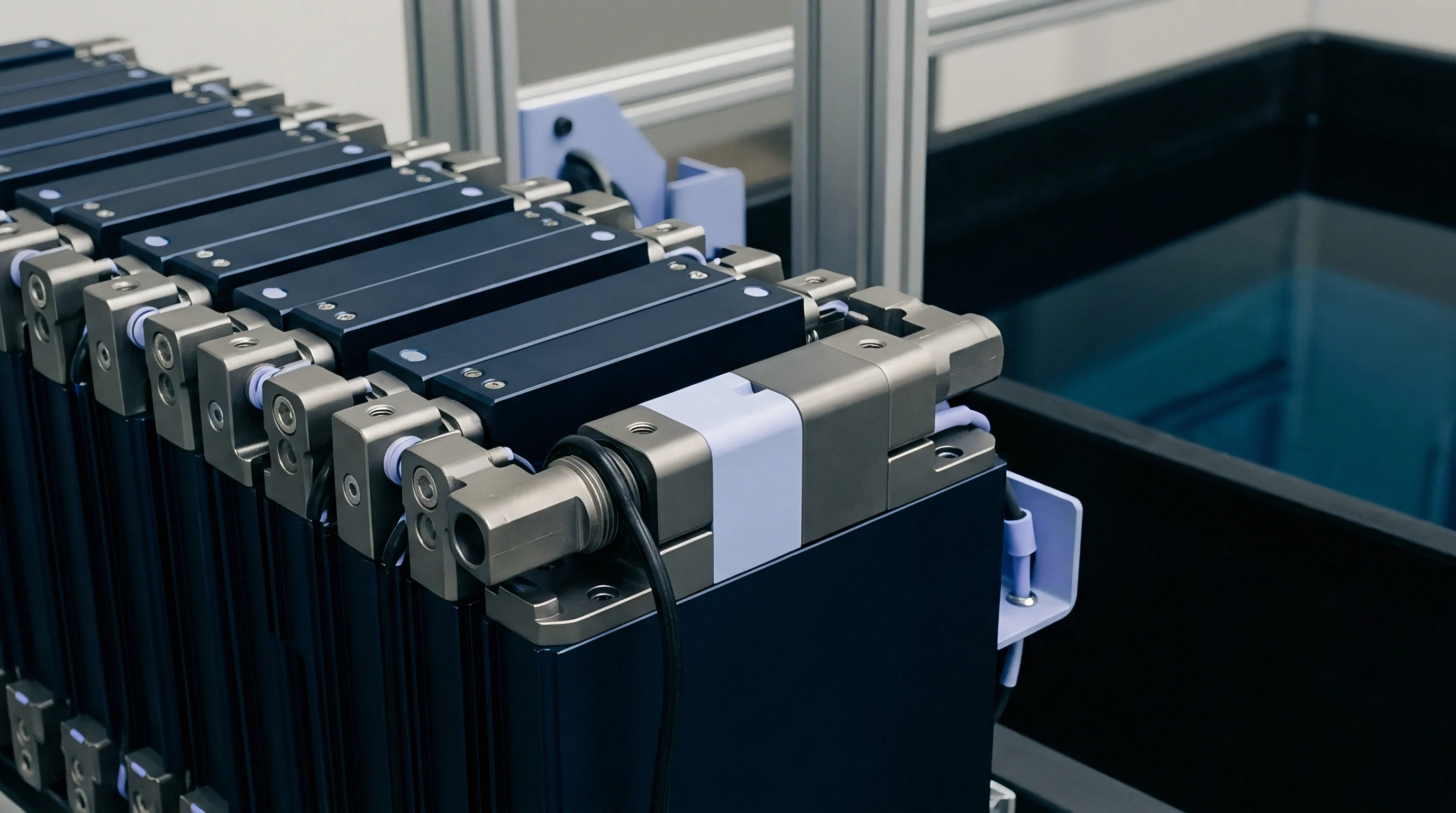
Sustained voltage gradients across thin interface layers cause electrical degradation over vehicle operational lifespans. Environmental factors like high humidity, elevated temperature, and ionic contamination accelerate partial discharge activity inside microscopic voids within the gap filler matrix. Trapped air pockets induce dielectric arc paths.
Moisture accelerates electrical breakdown inside voids. Water vapor diffusing into cured thermal interface compounds reduces volume resistivity and accelerates electrochemical dendrite growth along filler particle interfaces. Dielectric qualification protocols demand electrical testing following aggressive environmental aging exposures.
| Material Configuration | Unaged Dielectric Strength (kV/mm) | Post-HAST Dielectric Strength (kV/mm) | Volume Resistivity (Ω·cm) | Minimum Safe BLT for 2.5 kV Isolation (mm) |
|---|---|---|---|---|
| Silicone Gap Filler (Filled) | 18.0 | 14.2 | 1 × 10¹⁴ | 0.25 |
| Polyurethane Gap Filler (Filled) | 15.0 | 10.5 | 1 × 10¹³ | 0.30 |
| Silicone Pad + PET Film Substrate | 25.0 | 22.8 | 1 × 10¹⁵ | 0.15 |
| Epoxy Structural Adhesive (Filled) | 12.0 | 8.0 | 1 × 10¹² | 0.40 |
- Continuous minimum thickness validation ensures metallic contact between cell base low points and cold plate high points never pinches the dielectric layer below 0.20 mm.
- Dielectric filler particle distribution requires uniform dispersion of non-conductive ceramic powders like aluminum oxide or aluminum nitride without conductive impurities.
- Creepage distance extension design specifies material bead squeeze-out width to prevent electrical arc tracking around the outer perimeter of cell bases.
- Partial discharge resistance testing verifies that internal air voids under nominal operating voltage gradients do not generate localized micro-arcing over time.
Long-term dielectric withstand voltage in ceramic-filled polyurethane liquids following ten years of high-vibration exposure in heavy transport applications remains unverified.


Qualification
Formally validating thermal interface materials involves rigorous thermal, mechanical, and environmental exposure protocols. Standardized material datasheets often state bulk thermal conductivity measured under ideal laboratory conditions, which fails to reflect performance inside a compressed, vibrating battery pack joint. Comprehensive qualification programs evaluate thermal resistance across aged, environmentally stressed test assemblies under operational clamp pressures.
Steady-state testing underestimates interface resistance, whereas transient testing methods provide realistic operational insights. Standard test configurations must capture interfacial contact resistance on actual battery-grade aluminum surface finishes alongside bulk material conduction properties.
Silicone-based gap fillers suffer from siloxane volatile migration that degrades optical sensors and high-voltage contactor surfaces over extended thermal cycling.

Standardized Test Methods
Determining material conductivity and thermal resistance across variable joint thicknesses utilizes specialized steady-state apparatus. ASTM D5470 standard test methods measure heat flux through a material placed between two polished meter bars under controlled parallel contact pressure. Test protocols must modify standard ASTM D5470 procedures by utilizing bead-blasted aluminum substrates matching prismatic cell base surface roughness (Ra 1.6 to 3.2 µm) to accurately capture real-world interfacial contact resistance.
Environmental durability testing subjects interface joints to accelerated aging conditions. Thermal shock cycling (-40 °C to +85 °C for 1,000 cycles) evaluates resistance to delamination caused by thermal expansion mismatch. Highly Accelerated Stress Testing (HAST at 110 °C, 85% relative humidity) forces moisture ingress to verify chemical hydrolytic stability in polyurethane and acrylic formulations.
Dossier Requirements for Mass Production
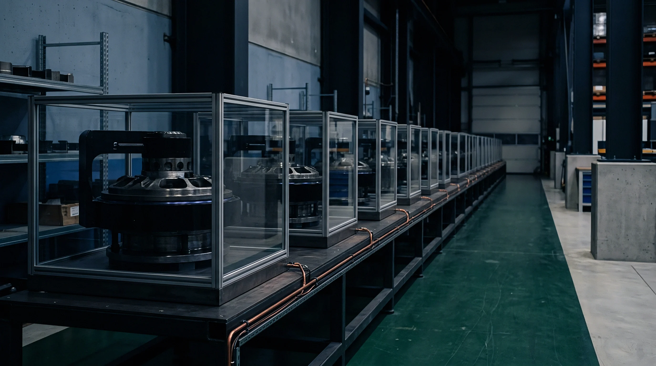
Submitting a complete engineering package for high-volume automotive production demands detailed material certification data. Production Part Approval Process (PPAP) documentation requires lot-to-lot consistency tracking for thermal conductivity, specific gravity, yield stress, and dielectric breakdown voltage. Supplier quality plans mandate batch sampling protocols to prevent un-cured or off-ratio chemical shipments from entering module assembly lines.
Reworkability determines pack repair economics. Qualification protocols evaluate module disassembly procedures when servicing failed cell groups. Rework testing measures the force required to shear cured gap filler joints without damaging adjacent cells or cold plate structures, alongside the chemical ease of cleaning residual interface compound off reusable cooling surfaces.
- ASTM D5470 thermal report containing bulk thermal conductivity and contact thermal resistance curves plotted across bond line thickness from 0.2 mm to 2.0 mm under 100 kPa to 500 kPa clamp force options.
- Rheological characterization report presenting viscosity, yield stress, and thixotropic recovery index data recorded across temperature sweeps from 15 °C to 50 °C.
- Environmental aging dossier documenting post-test thermal resistance, dielectric withstand voltage, and lap shear adhesion strength following 1,000 hours of 85 °C / 85% RH exposure and thermal shock cycling.
- Outgassing volatility certificate defining total mass loss (TML) below 1.0% and collected volatile condensable material (CVCM) below 0.1% according to ASTM E595 testing standards.
- Reworkability procedure specification detailing mechanical separation force requirements and approved solvent cleaning agents for field repair workflows.
Disassembly procedures for pack servicing rely on low-shear formulation chemistry that releases clean from anodized aluminum cold plates without leaving particulate residue.