Quantifying Internal Argon Entrapment Kinetics and Thermally Induced Porosity in Consolidated Atomized Tool Steels
Internal argon trapped during atomization expands under heat treatment, requiring strict desorption limits to prevent thermally induced porosity.


Melt
Inert gas atomization introduces insoluble argon directly into molten high-alloy tool steel during stream breakup. As liquid metal exits the tundish nozzle in a 3.0 mm to 6.0 mm stream, high-velocity argon jets pressurized between 2.0 MPa and 5.0 MPa strike it, subjecting super-heated droplets to rapid deceleration and aerodynamic shear within the tower. Recirculation eddies in the plume entrain ambient gas, trapping argon pockets inside the liquid droplets before surface tension rounds them into spheres.
Cooling rates between 1,000 K/s and 100,000 K/s then quickly freeze these internal cavities, locking argon bubbles inside the solid particles.
Atomization gas pressure and melt superheat temperature directly set the volume fraction of hollow particles. Higher pressure drives up jet turbulence and velocity gradients, yielding finer droplets but trapping gas bubbles more frequently. In-flight collisions between molten droplets and smaller, already-solidified satellites create secondary voids at the interface, sealing extra argon under the molten skin.
Once trapped inside these internal voids, the argon cannot escape during collection, cyclone separation, or screening; solid iron alloys are virtually impermeable to noble gases at ambient conditions.

Droplet Breakup Dynamics and Entrapment Kinetics
Fluid dynamics inside the nozzle orifice govern early gas-to-liquid interactions. High-speed framing and optical phase-Doppler analysis show stream disintegration progressing through primary Rayleigh-Taylor instability waves before secondary sheet breakup occurs. Argon gas becomes enclosed whenever turbulent pressure fluctuations exceed the liquid stream’s capillary pressure.
Because capillary pressure scales inversely with droplet radius ~ calculated via the Young-Laplace relation, with tool steel surface tension averaging 1.6 N/m at 1550 °C ~ larger droplets with lower internal pressure trap argon far more readily than fine droplets below 15 µm.
Gas atomization naturally leaves internal pockets inside the powder. Initially, argon pressure within a frozen particle balances against surface tension and atomization chamber pressure. Shrinkage of the liquid metal during cooling expands the void, dropping cold argon pressure inside the hollow particle below atmospheric levels.
Chemical analysis shows this gas concentrated in specific size fractions: fine powders under 45 µm carry low argon mass fractions, while coarse fractions above 150 µm hold substantially higher gas volumes per unit mass.
Routine audits of atomization facilities verify argon back-purge pressure during tundish casting. Fluctuation of tundish pressure beyond 5 kPa destabilizes the liquid metal stream, triggering wave oscillations that ingest purging gas from the upper tundish housing. While operating atomization nozzles at higher gas-to-metal mass ratios yields smaller mean particle sizes, total gas content rises if nozzle alignment drifts off-center by more than 0.25 mm.
Aligning gas jet orifices precisely maintains a symmetric stagnation point, minimizing vortex engulfment at the liquid core.
| Powder Size Range (µm) | Sieve Mesh Equivalent | Mean Particle Volume (cm³) | Hollow Particle Fraction (%) | Argon Mass Fraction (ppm) |
|---|---|---|---|---|
| > 250 | +60 Mesh | 8.18 × 10⁻6 | 14.2 | 2.85 |
| 150 to 250 | -60 / +100 Mesh | 2.21 × 10⁻6 | 8.6 | 1.42 |
| 90 to 150 | -100 / +170 Mesh | 5.23 × 10⁻7 | 3.8 | 0.68 |
| 45 to 90 | -170 / +325 Mesh | 1.18 × 10⁻7 | 1.1 | 0.22 |
| < 45 | -325 Mesh | 1.41 × 10⁻8 | 0.1 | 0.04 |

Powder Sieve Fractions and Argon Volume Concentration
Classifying atomized tool steel powder into production fractions directly alters the gas payload entering hot consolidation. Screening out particles above 150 µm cuts total argon by up to 70 percent in high-speed grades like ASP 2060 and CPM 10V. Aggressive screening comes with a yield penalty, however, reducing total mass recovery by 12 to 18 percent and raising raw powder costs per kilogram.
Producers typically balance gas limits against atomization yield by adjusting melt superheat and nozzle geometry rather than relying entirely on sieving.
Morphology checks show a strong correlation between satellite attachment and gas retention. High chamber gas densities force solidified fine particles back into the primary atomization plume. When these cold particles strike larger liquid droplets, they embed in the soft surface, leaving micro-pockets of argon encapsulated at the interface that survive screening.
Argon gas atomization at gas-to-metal ratios exceeding 2.2 kg/kg increases hollow particle counts in powder fractions above 150 µm by more than three hundred percent.
Outgassing procedures at elevated temperatures cannot extract argon from internal powder voids. Vacuum outgassing unconsolidated powder cans at 400 °C removes moisture, hydrocarbons, and surface-adsorbed nitrogen, but leaves internal gas pockets untouched. Argon cannot dissolve in solid iron; its 0.071 nm atomic radius prevents interstitial or substitutional diffusion through BCC or FCC iron lattices below the melting point.
Gas trapped during atomization thus remains inside the powder structure throughout handling, blending, and canister filling.
Argon levels below 2.0 ppm by weight yield apparently fully dense billets under standard hot isostatic pressing schedules. Residual internal gas remains trapped in nanometer-scale pores without affecting room-temperature mechanical performance or standard dimensional checks.


Kinetics
Hot Isostatic Pressing consolidates atomized powder into solid billets using simultaneous heat and pressure inside a sealed vessel. Processing tool steels at 1,100 °C to 1,200 °C under argon pressures of 103 MPa to 150 MPa for 3 to 5 hours lowers matrix yield strength enough for plastic deformation, creep, and grain boundary diffusion to close inter-particle voids. Outgassed powder cans shrink by roughly 15 percent by volume, reaching an apparent density above 99.99 percent of theoretical limits.
Trapped argon alters void collapse kinetics during consolidation. As external pressure drives the steel matrix inward, the gas contracts and its internal pressure climbs rapidly, following non-ideal behavior described by the Noble-Abel or Modified Benedict-Webb-Rubin equation of state. Once the pore radius drops below 1 µm, internal gas pressure rises until it matches the applied hydrostatic pressure of 100 to 150 MPa.
Mechanical compression then halts, leaving the argon bubble in equilibrium with the matrix as a microscopic high-pressure pocket inside the billet.
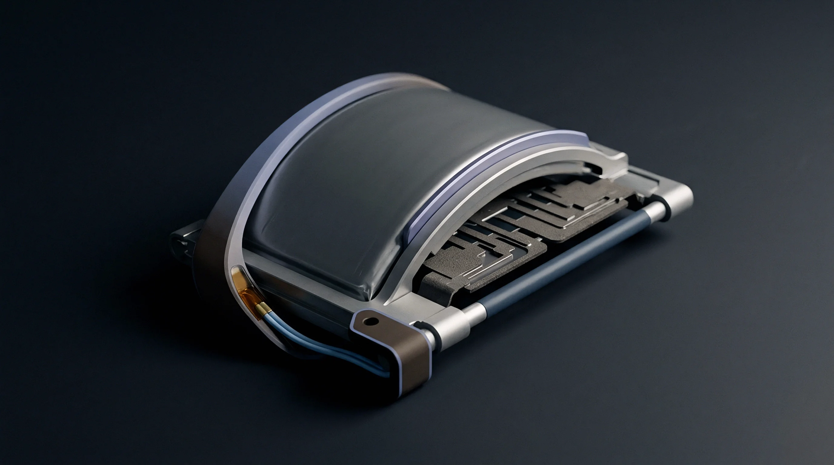
Pore Mechanics during Hot Isostatic Pressing
Compression mechanics prevent micro-voids from disappearing entirely; they shrink until internal pressure balances external forces. Equilibrium pore radius after consolidation depends on initial gas volume, temperature, and hydrostatic pressure. Combining power-law creep mechanics with matrix yield stress conditions shows that an initial 50 µm hollow particle containing argon at 0.05 MPa compresses to a stable radius of 0.2 µm to 0.5 µm under a 100 MPa cycle at 1,150 °C.
Cooling to room temperature relieves external hydrostatic pressure and transforms the matrix into martensite or annealed ferrite-carbide structures. With room-temperature yield strength rising above 1,500 MPa, the matrix easily contains the compressed argon pocket. As the trapped gas cools, its internal pressure falls to 15 MPa ~ 40 MPa, remaining stable because the rigid matrix prevents plastic expansion or creep at ambient conditions.
This trapped gas remains dormant until subsequent thermal processing warms the steel. Forging, hot rolling, stress relieving, and austenitizing subject components to temperatures between 1,020 °C and 1,230 °C. As heat softens the matrix and degrades creep resistance, internal argon pressure rises linearly with absolute temperature according to real-gas thermodynamic relations.
| Thermal Exposure Temp (°C) | Exposure Time (Hours) | Initial Pore Radius (µm) | Final Pore Radius (µm) | Internal Gas Pressure (MPa) | Matrix Yield Strength (MPa) |
|---|---|---|---|---|---|
| 20 (As-HIPed) | 0 | 0.35 | 0.35 | 28.4 | 1,850 |
| 1,050 | 4 | 0.35 | 0.48 | 42.1 | 115 |
| 1,150 | 8 | 0.35 | 0.82 | 21.6 | 48 |
| 1,150 | 24 | 0.35 | 1.45 | 8.2 | 48 |
| 1,220 | 12 | 0.35 | 2.80 | 3.1 | 22 |
Thermal Expansion Forces and Vacancy Diffusion
Thermally Induced Porosity (TIP) begins when internal gas pressure exceeds the temperature-dependent threshold stress for matrix deformation. High-temperature expansion proceeds through plastic yield deformation and vacancy diffusion creep. Plastic yield occurs when internal pressure generates hoop stresses higher than the matrix yield strength ~ a mechanism dominant during rapid heating above 1,150 °C that causes rapid expansion within minutes of thermal equalization.
Vacancy diffusion creep takes over during extended high-temperature holds. Surrounding grain boundaries supply atomic vacancies, which migrate toward pore walls along the stress gradient created by internal gas pressure. Governed by Nabarro-Herring lattice diffusion and Coble grain-boundary diffusion, volumetric expansion rates depend on iron atom diffusivity and grain-boundary transport away from the pore perimeter.
Pore expansion increases internal volume and lowers gas pressure until it balances the back-stress of surface energy and ambient pressure. In fine-grained tool steels, Coble creep drives diffusion growth between 1,000 °C and 1,150 °C because of high grain-boundary surface area. Above 1,200 °C, Nabarro-Herring lattice diffusion becomes the primary mechanism for rapid pore regrowth.

Matrix Creep Stress and Pore Volume Expansion
Alloy chemistry sets resistance to pore growth by altering high-temperature matrix creep strength. Steels rich in refractory carbide formers like vanadium, tungsten, molybdenum, and niobium retain higher yield strengths than lower-alloy cold-work grades. CPM 10V, containing 9.75 percent vanadium, forms dense vanadium carbide (VC) distributions that pin grain boundaries and block dislocation movement, retarding matrix creep and suppressing argon pore growth during 1,150 °C holds.
Grades with lower carbide volume fractions swell rapidly under identical heating cycles. Clusters of argon micro-voids near prior particle boundaries act as collective vacancy sinks, coalescing into micro-cracks or void chains that severely degrade localized fracture toughness.
Standard austenitizing heat treatments at 1,180 °C convert compressed sub-micron argon bubbles into visible micro-porosity exceeding two micrometers in diameter within four hours of hold time.
Macroscopic density changes reflect this volumetric swelling. A consolidated block with an initial density of 7.420 g/cm³ can drop to 7.395 g/cm³ after 24 hours at 1,150 °C ~ a 0.34 percent volumetric expansion caused entirely by internal argon void growth.
The exact transition point where localized vacancy diffusion gives way to unconstrained dislocation climb during dynamic industrial heating cycles remains uncertain.


Creep
Microstructural damage from Thermally Induced Porosity weakens components operating under thermal or cyclic stress. Spherical gas pores act as stress concentrators where dynamic loads initiate micro-cracks that propagate quickly through carbide-rich structures, stripping high-wear tool steels of essential toughness reserves during heat treatment.
Transverse Rupture Strength (TRS) indicates material damage from argon entrapment. Sound, fully dense high-speed steel typically reaches TRS values of 3,500 MPa to 4,200 MPa after standard hardening and triple tempering. If argon bubbles swell beyond 2 µm during austenitizing, TRS drops by 20 to 45 percent.
Scanning electron microscopy of fracture surfaces reveals smooth-walled spherical dimples typical of unbonded gas pockets at crack initiation sites.

Can High Heat Drive Pore Regrowth?
High temperatures during tool fabrication or service routinely trigger pore regrowth in consolidated stock. Forging billets at 1,100 °C to 1,180 °C subjects argon voids to intense multi-axial strain. While mechanical deformation flattens pores along working axes, it extends them along lateral shear directions.
Gas pressure prevents void surfaces from metallurgically welding closed; once forging pressure lifts, internal pressure forces the un-welded surfaces apart into elongated micro-laminations along flow lines.
Subsurface voids exposed near component boundaries during grinding and polishing become surface pits or pinholes. Because SPI A1 mirror finish standards tolerate no pinholes larger than 1 µm per square centimeter, argon-induced porosity often leads to costly mold rejections after hundreds of hours of precision machining.
Hot-work PM steel tools in high-pressure die casting experience repeated thermal shock, with surface temperatures exceeding 700 °C per cycle. Gas pockets in high-heat zones expand incrementally, merging with surface thermal stress cracks and accelerating thermal fatigue until premature heat checking fails the tool.

Structural Degradation and Dynamic Fatigue Limits
Fatigue resistance under dynamic stress degrades directly with maximum pore size in the stressed zone. Cyclic bending tests at R = 0.1 show a sharp drop in endurance limit as argon voids grow. Pores within 50 µm of the surface are particularly damaging, triggering localized shear bands under low cycle counts.
Structural damage modes linked to argon entrapment and thermally induced porosity include:
- Transverse Rupture Degradation drop in bending failure resistance due to spherical void stress concentration nodes acting as sharp crack initiation sites under peak tensile loading.
- Mirror Polish Rejection surface pitting appearing during high-grade diamond compound polishing caused by intersecting expanded argon micro-voids located beneath ground surfaces.
- Thermal Fatigue Cracking accelerated initiation of heat-checking networks in hot-work dies driven by cyclic pressure expansion of internal gas pockets during thermal shock loading.
- Impact Fracture Sensitivity severe reduction in Izod and Charpy V-notch impact energy absorption caused by prior particle boundary weakening where sub-micron gas bubbles concentrate.
Toughness drops rapidly once pore size exceeds the matrix’s mean inter-carbide distance. In high-speed steels with 1.2 µm carbide spacing, pore growth past 1.5 µm disrupts the continuous matrix, opening unreinforced paths for fast crack propagation.
Tool steel billets carrying total argon concentrations above 0.8 ppm lose over thirty percent of their rotating beam fatigue strength following standard 1,150 °C hardening cycles.
HIP billets are rejected when carrier gas thermal desorption reveals argon concentrations exceeding 0.45 parts per million. In material destined for plastic injection mold inserts requiring an SPI A1 optical finish, downstream machining exposes subsurface voids, destroying the mirror finish during final polish.
Internal gas volume ultimately dictates service life in high-stress tooling operations, making billets with unquantified argon pockets a continuous liability for tool builders.
Metallography
Verifying internal argon content and Thermally Induced Porosity quantitatively requires analytical testing across powder samples, consolidated billets, and heat-treated components. Archimedes density testing, optical metallography, high-resolution X-ray computed tomography (µCT), and carrier gas thermal desorption mass spectrometry (TDMS) provide complementary measurements of gas volume and pore distribution.
Archimedes density testing per ISO 3369 and ASTM B311 serves as the primary screening method for consolidated billets. Using balances accurate to 0.1 mg with temperature-compensated fluids like deaerated distilled water or tetrabromoethane, the technique detects density shifts down to 0.001 g/cm³. Room-temperature testing alone, however, cannot separate carbide-segregation density shifts from void deficits caused by sub-micron argon bubbles.

High-Precision Archimedes Density Protocol
The standard Thermal Induced Porosity (TIP) test protocol overcomes room-temperature limits by measuring density changes after controlled heating. Core specimens undergo baseline density testing, followed by vacuum heat treatment at 1,150 °C for 24 hours below 10⁻³ Pa to prevent surface oxidation and decarburization. After slow cooling, density is re-measured using identical fluids and temperature corrections.
Calculating the density drop quantifies volume swelling from argon pore expansion. A drop exceeding 0.05 percent signals an unacceptable gas volume that compromises high-temperature performance or surface finish. High-precision balances require calibration against single-crystal silicon density standards before each test sequence.
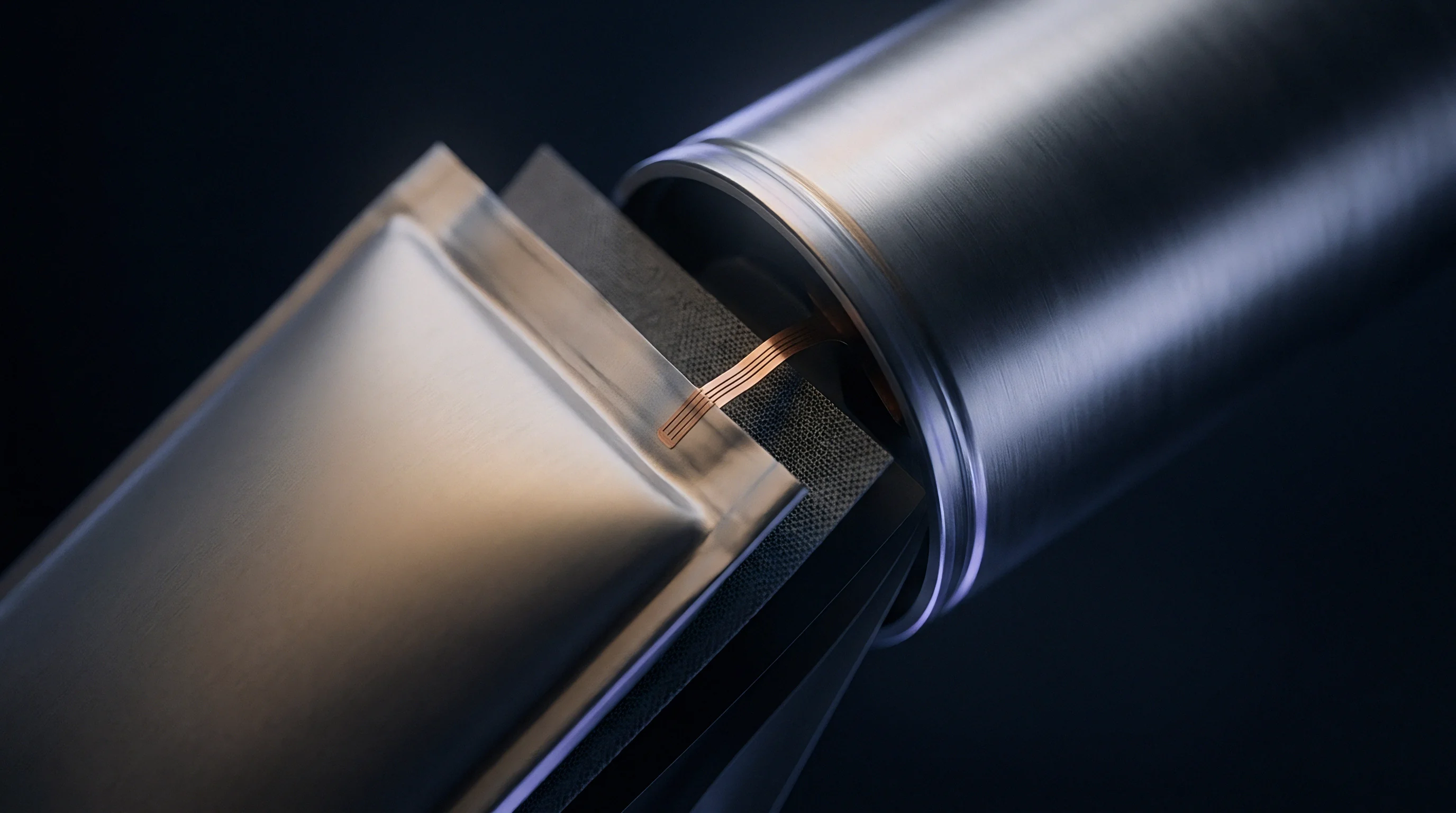
Carrier Gas Thermal Desorption Mass Spectrometry (TDMS) directly measures absolute argon mass fractions in parts per million (ppm). A 1.0 g to 5.0 g solid steel sample is heated past its liquidus temperature to 1,600 °C in a graphite crucible under flowing helium, releasing all trapped argon into the carrier gas stream.
Thermal Desorption Spectroscopy and Gas Quantification
The gas passes through moisture traps and dust filters into a quadrupole mass spectrometer tuned to atomic mass unit 40 (argon). Calibrated with certified argon-in-helium gas mixtures, the system maintains linear response across four orders of magnitude down to 0.01 ppm argon by weight. This destructive outgassing protocol serves as the definitive reference for commercial quality disputes.
High-resolution X-ray computed tomography (µCT) non-destructively maps 3D pore distributions within consolidated structures. Synchrotron radiation µCT reaches resolutions of 50 nm per voxel to capture individual micro-voids in small pins, while laboratory micro-CT systems operating at 1.0 µm to 3.0 µm map macroscopic pore clusters, boundary voids, and TIP expansion zones in larger samples.

Image Analysis and Tomographic Resolution Limits
Quantitative image analysis per ASTM E1245 measures stereological pore features ~ area fraction, mean equivalent diameter, maximum pore size, and aspect ratios ~ on polished cross-sections. Preparing samples requires diamond polishing down to 0.25 µm without etching to prevent void edge rounding. Automated systems scan at least 100 random fields at 500x magnification to build statistical size distributions.
Executing a certified factory audit of internal argon entrapment requires adherence to a standardized sequential testing sequence:
- Extract a 15 mm × 15 mm × 50 mm core sample from the center of the consolidated powder metallurgy billet using water-jet cutting to prevent thermal input.
- Perform baseline Archimedes density testing in triplicates using deaerated distilled water at 20.0 °C, recording average mass to 0.1 mg precision.
- Seal the test sample inside a quartz tube evacuated to a pressure below 10⁻⁴ Pa or place it inside a clean vacuum furnace chamber.
- Heat the sample at 10 °C/min to 1,150 °C, hold for 24 hours, and cool at 5 °C/min back to ambient room temperature.
- Re-measure specimen density using identical Archimedes balance procedures and calculate percentage volumetric swelling.
- Section the sample longitudinally, polish to a 0.25 µm finish, and perform ASTM E1245 optical quantitative image analysis across 100 fields.
- Melt a 2.0 g cross-sectional slice in a thermal desorption furnace to quantify absolute argon mass fraction via quadrupole mass spectrometry.
| Analytical Technique | Detection Limit | Sample Destructive? | Sample Size / Volume | Primary Measurement Output | Turnaround Time |
|---|---|---|---|---|---|
| Archimedes Density (TIP Test) | 0.001 g/cm³ (0.01% swell) | Non-destructive (pre-sectioning) | 10 cm³ to 50 cm³ block | Macro volumetric density change | 28 Hours |
| Optical Metallography (ASTM E1245) | 0.5 µm pore diameter | Destructive sectioning | 20 mm × 20 mm area | 2D Area fraction, pore size distribution | 4 Hours |
| Mass Spectrometry (TDMS outgassing) | 0.01 ppm argon by mass | Fully destructive melt | 1.0 g to 5.0 g coupon | Absolute argon mass concentration | 2 Hours |
| Laboratory X-ray Tomography (µCT) | 1.5 µm spatial voxel size | Non-destructive | 5 mm diameter cylinder | 3D Void morphology and spatial clustering | 6 Hours |
Comparative data confirms light microscopy undercounts sub-micron argon pores by up to 60 percent due to resolution limits. Combining thermal desorption mass spectrometry with pre- and post-heat treatment density testing provides reliable quantitative proof for batch certification.
Thermal desorption mass spectrometry testing detects residual argon mass fractions down to 0.01 ppm by melting solid samples in high-purity helium streams.
An uncalibrated optical image analysis system failing to resolve sub-micron argon pockets in a lot of hot-work tool steel led to a twelve thousand dollar loss from premature mold failure during production casting trials.


Ledger
Tooling manufacturers and powder mills divide commercial responsibility for internal gas defects through formal procurement agreements. Standard purchase orders specifying only alloy chemistry and macro-hardness fail to protect buyers from argon entrapment risks. Billet specifications must explicitly define gas ceilings, standardized TIP test conditions, density swell tolerances, and scrap liability allocation.
Tooling failures carry heavy financial penalties. When an injection mold or cold-heading die fails from surface voids during optical polishing, the raw billet represents less than ten percent of the total loss. CNC milling, EDM, heat treatment, and manual polishing account for ninety percent of component value, making strict procurement terms essential to protect downstream investment.

Contractual Argon Thresholds and Billet Guarantees
Billet purchase orders are structured to divide mill responsibility at the hot isostatic pressing boundary. Contractual terms mandate that powder mills provide heat-lot certificate documentation including certified mass spectrometry argon values for every consolidated master billet. Steel mills must warrant that argon gas concentrations remain below 0.20 ppm by weight for standard tool grades and below 0.05 ppm by weight for premium mirror-polish mold grades.
Mill certificates must detail the TIP test protocol used to verify thermal stability. Purchase orders typically require central coupon samples from every HIP billet to undergo 24 hours of vacuum testing at 1,150 °C, showing a density reduction no greater than 0.02 percent. Lots exceeding this threshold face rejection at incoming inspection, with return credits covering freight and testing.
Quality agreements separate atomization defects from downstream heat-treating errors. Overheating a component beyond its upper critical temperature during hardening can trigger swelling even in low-argon material. Quality audits rely on furnace logs and carbide grain boundary microstructures to verify heat-treatment compliance.
Allocation of Liability across Powder and HIP Seams
Contracts must account for split supply chains where atomization, canning, and hot isostatic pressing occur at separate entities. Clear liability demarcation prevents disputes: atomizers remain responsible for argon retention inside the powder, while HIP toll processors answer for canister vacuum integrity during outgassing and seal-off.
Verification checklists for receiving consolidated PM tool steel billets include the following requirements:
- Mass Spectrometry Certification signed heat-lot report verifying total atomic argon concentration below specified ppm thresholds measured via carrier gas thermal desorption.
- Thermal Porosity Test Verification certified pre- and post-test density data proving total volumetric swelling remains below 0.02 percent following 1,150 °C vacuum holding.
- Ultrasonic Attenuation Audit non-destructive immersion ultrasonic testing report verifying freedom from macro-porosity clusters or un-consolidated prior particle boundaries.
- Chemical Analysis Traceability complete elemental composition report matching specified tool steel grade chemistry limits including trace gas elements.
- Microstructural Cleanliness Report stereological optical metallography analysis confirming carbide grain size uniformity and absence of micro-void networks.
Clear contract language prevents lengthy disputes when argon porosity surfaces late in die production. Holding suppliers to measurable physical standards before machining begins provides effective financial protection.
Contractual guarantees specifying maximum allowable density drops under 0.02 percent after 24-hour thermal testing shift financial liability for scrap costs directly back to the powder mill.
Master purchase contracts often mandate that if certified mass spectrometry proves internal argon porosity exceeds 0.20 ppm by mass, the powder mill must refund material costs and reimburse proven machining labor up to three times the billet’s purchase value.