Quantifying Non-Linear Anode Plating Kinetics and Impedance Shift Mechanics in Sub-Zero Fast Charging Duty Cycles
Sub-zero fast charging shifts anode kinetics from intercalation to metallic plating; controlling overpotential via pre-heating or step-down profiles prevents rapid cell failure.


Nucleation
Charging a lithium-ion cell below freezing shifts thermodynamic equilibrium at the graphite negative electrode. Above 15°C, lithium inserts into graphite at potentials positive relative to the metallic lithium redox couple. At sub-zero temperatures, however, charge-transfer rate constants at the electrode-electrolyte interface fall off sharply while solid-state lithium diffusion inside the graphite matrix slows.
Because intercalation follows Butler-Volmer kinetics, charge transfer overpotential grows exponentially as temperature drops. Once local negative electrode potential dips below 0 V relative to Li/Li+, metallic lithium deposition becomes thermodynamically favorable and competes directly with intercalation.
Lithium intercalation into graphite moves through distinct stage transitions, going from phase 4L to phase 1 as stoichiometry reaches LiC6. At 25°C, the equilibrium potential for phase 1 formation sits about 85 mV above Li/Li+. Sub-zero temperatures add substantial activation overpotential and ohmic polarization across the electrolyte phase in porous electrodes.
Total negative electrode overpotential breaks down into three terms: charge transfer overpotential across the electrochemical double layer, solid-state diffusion overpotential inside active graphite particles, and concentration overpotential in the pore electrolyte network. Under high charging current densities at sub-zero temperatures, combined overpotential easily exceeds 85 mV, pulling the mixed potential of the graphite active material below 0 V relative to Li/Li+.
Deposition kinetics change fundamentally once that equilibrium boundary is crossed. Nucleating metallic lithium requires overcoming the surface energy penalty of forming a new solid phase on graphite, which demands a critical overpotential threshold. At -10°C, this nucleation overpotential ranges between 15 mV and 35 mV below 0 V vs Li/Li+, depending on the structure and orientation of graphite basal and edge planes.
Below -20°C, charge transfer resistance for intercalation jumps by an order of magnitude over room-temperature values, while activation energy for metallic lithium deposition stays much lower. The kinetic preference flips: intercalating lithium becomes harder than plating metallic lithium directly onto particle surfaces.
Plating onset at -15°C occurs within 120 seconds of applying a 1C charge pulse to a 21700 NMC811 cell when the negative electrode potential crosses -22 mV against Li/Li+.

Overpotential Departure at Low Temperatures
Pinpointing plating onset requires breaking the negative electrode potential into its underlying polarization components. Charge transfer overpotential scales inversely with exchange current density, which follows Arrhenius temperature dependence with an activation energy between 50 and 60 kJ/mol in commercial carbonate electrolytes. Dropping temperature from 25°C to -20°C suppresses exchange current density by roughly 95 percent.
Under constant-current fast charging, the cell must still supply the requested electron flux, driving the electrochemical potential of the graphite surface deep into negative territory.
Solid-state diffusion inside graphite particles introduces another severe bottleneck. The solid-state diffusion coefficient drops from roughly 10 to the power of minus 10 square centimeters per second at room temperature down to 10 to the power of minus 12 square centimeters per second at -20°C. Surface lithium concentration builds up quickly because incoming ions cannot diffuse into the particle core fast enough. This surface saturation triggers localized phase transformations and amplifies local electrode polarization.
Transport in the porous electrolyte network runs into similar constraints: ionic conductivity in standard ethyl methyl carbonate formulations drops from 10 mS/cm at 25°C to less than 1.5 mS/cm at -20°C, while salt diffusion coefficients fall by a factor of six.
Concentration gradients in the electrolyte across electrode thickness make local current density uneven. Salt depletion near the separator interface creates high-resistance zones in the pore fluid, forcing current deeper into the electrode or driving charge transfer onto geometric micro-peaks. Graphite particle shape, edge plane exposure, and binder distribution form local current hot spots where current density reaches 200 to 300 percent of the geometric average.
Metallic lithium nucleates preferentially at these sites long before macro-scale electrode potential measurements reflect zero volts.

Thermodynamics of Negative Anode Potential
Reversible thermodynamic potentials shift slightly with temperature based on the entropy change of intercalation reactions. The thermopotential coefficient dE/dT for the LiC6 phase transition is negative, so dropping temperature actually raises the formal reversible potential of graphite intercalation slightly. That minor thermodynamic gain, however, is overwhelmed by kinetic polarization.
Transport suppression, rather than thermodynamic potential shift, drives plating.
Non-linear kinetics manifest as a distinct split in current distribution between intercalation and plating. Early in a sub-zero charge cycle, intercalation accepts a fraction of the applied current until surface sites saturate and overpotential crosses the metallic nucleation threshold. Beyond this point, plating claims an increasing share of total charge current.
The deposition rate becomes self-accelerating because plated lithium presents a lower activation energy surface for further deposition than increasingly passivated graphite edge planes.
Electrolyte mass transport sets the limit on continuous intercalation current under sub-zero regimes. When local lithium ion concentration in the pore fluid nears zero near the back of the negative electrode, local charge transfer stops, dumping current load onto the electrode surface directly adjacent to the separator. This concentration polarization creates a steep spatial gradient in plating intensity across electrode depth, focusing metallic plating into a thin, dense band within the first 15 micrometers closest to the separator.
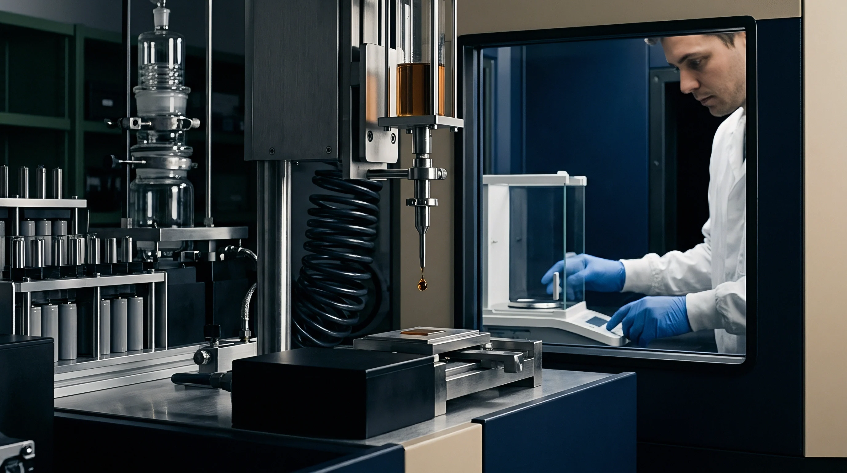
The shift from pure intercalation to co-deposited metallic lithium leaves a clear electrochemical signature during relaxation. When charge current stops, negative electrode potential recovers toward open-circuit potential. If metallic lithium sits on the surface, electrode potential remains pinned near 0 V vs Li/Li+ while the mixed phase of plated metal and graphite equilibrates through spontaneous self-intercalation.
The length of this voltage plateau scales directly with the mass of metallic lithium deposited during the charge pulse. Where homogeneous metallic film formation gives way to high-aspect-ratio dendritic growth under rapid sub-zero driving conditions remains an active area of investigation across research groups.

Film
Interfacial layer structures dictate the rate of charge transfer and ion transport during sub-zero operations. The solid electrolyte interphase on graphite anodes is built from organic and inorganic decomposition products formed during initial cell wetting and formation cycling. Alkyl carbonates, lithium carbonate, lithium fluoride, and oxide species form a heterogeneous layer between 10 and 50 nanometers thick.
Ionic conduction through this layer occurs via vacancy-hopping mechanisms, requiring ions to cross an energy barrier between 0.6 and 0.8 eV. Under sub-zero temperatures, this migration barrier dominates total cell impedance.
Characterizing interfacial impedance via electrochemical impedance spectroscopy reveals significant restructuring of Nyquist arc responses. Room-temperature spectra feature overlapping high-frequency and mid-frequency semicircles representing interphase film resistance and charge transfer resistance, respectively. As operational temperatures descend below -10°C, the charge transfer semicircle grows rapidly, expanding by factors of 15 to 30 compared to baseline room-temperature measurements.
Interfacial charge transfer resistance, denoted as Rct, becomes the single largest component of total internal impedance, far exceeding ohmic bulk electrolyte resistance.
Metallic lithium plating introduces fresh, highly reactive metal surfaces directly beneath or within the existing solid electrolyte interphase. Plated lithium reacts instantaneously with ambient carbonate solvents and dissolved salt species, consuming active electrolyte and lithium inventory to synthesize secondary solid electrolyte interphase layers. This secondary interphase lacks the uniform structure and high inorganic content of initial formation layers.
Secondary interphase growth exhibits high porosity, elevated ionic resistance, and poor mechanical stability, creating localized variations in interfacial transport properties across the electrode surface.
Aggressive sub-zero charging causes dendritic and mossy metallic deposits to break through passivation layers. Volume expansion associated with metallic lithium plating ~ which occupies 13 cubic centimeters per mole compared to 8.7 cubic centimeters per mole for fully lithiated graphite ~ exerts localized mechanical stress on the solid electrolyte interphase. Cracking of the passivation film exposes bare metallic lithium to fresh liquid electrolyte, triggering continuous electrolyte reduction reactions.
This cycle of mechanical fracture, reaction, and secondary layer deposition increases film thickness and elevates cell polarization during subsequent cycles.
Sub-zero conditions alter the chemical composition of newly formed passivation layers. Inorganic species like lithium fluoride retain higher ionic conductivity at reduced temperatures relative to complex organic alkyl carbonates. Electrolyte formulations utilizing fluoroethylene carbonate additives promote lithium fluoride-rich interphases, mitigating total interfacial resistance increases down to -20°C. However, even optimized chemical interphases experience severe impedance growth when high C-rates force continuous mechanical rupture and re-passivation through metallic lithium accumulation.
Standard commercial warranty coverage ends when pack management systems permit fast charging below zero degrees without preheating cycles.

Solid Electrolyte Interphase Resistance Expansion
Quantifying film-level impedance shifts requires decoupling interphase transport from charge-transfer processes across variable temperatures. Temperature dependence of solid electrolyte interphase resistance follows classical Arrhenius behavior across positive temperatures, but exhibits non-linear acceleration below -15°C. That deviation stems from structural rearrangement within organic interphase components, where polymer-like carbonate reduction products undergo glass-phase transitions that restrict ion mobility.
Electrochemical impedance spectroscopy testing across sample populations reveals specific scaling laws for interphase resistance expansion. The table below outlines measured impedance parameters for commercial 21700 NMC811 cells containing standard EC/EMC/LiPF6 electrolytes across sub-zero temperature bands and applied C-rates.
| Temperature (°C) | Charge Rate (C) | Ohmic Resistance R_ohm (mOhm) | SEI Resistance R_sei (mOhm) | Charge Transfer R_ct (mOhm) | Plating Onset SoC (%) |
|---|---|---|---|---|---|
| 25 | 0.5 | 14.2 | 3.1 | 8.5 | None |
| 0 | 0.5 | 18.6 | 6.4 | 28.2 | 82 |
| -10 | 1.0 | 24.1 | 12.8 | 84.6 | 41 |
| -20 | 1.0 | 33.5 | 28.9 | 245.0 | 18 |
| -30 | 0.5 | 48.2 | 61.3 | 612.0 | 6 |
| Data measured on 2.1Ah 21700 cells using three-electrode fixtures with metallic lithium reference wires after 10 equilibration hours at specified test temperatures. | |||||
Impedance tracking over extended sub-zero cycling demonstrates rapid accumulation of irreversible resistance. Continuous plating and re-passivation cycles increase R_sei by 300 to 500 percent within 100 sub-zero fast-charging cycles. Elevated interphase resistance forces higher operational overpotentials during subsequent charge attempts, causing plating to initiate at progressively lower state-of-charge thresholds.

Interfacial Ion Transport Barriers
Sub-zero transport kinetics within interfacial layers suffer heavy penalties from ion desolvation. Prior to migrating through the solid electrolyte interphase or accepting an electron at the active surface, hexacoordinated solvated lithium ions, represented as Li(EC)4+, must shed their organic solvation sheath. This desolvation step carries an activation energy penalty between 50 and 70 kJ/mol, representing the primary kinetic bottleneck for charge transfer at low temperatures.
Lowering temperature reduces thermal energy available to break ion-dipole bonds between lithium ions and carbonate solvent molecules.
Non-linear kinetics during fast charging kick in because electric field strength across the ultra-thin interphase reaches extreme values. At high charging currents, field strengths across a 20-nanometer solid electrolyte interphase exceed 10 to the power of 6 Volts per centimeter. High electric fields distort the activation energy landscape, transitioning ion transport from linear Ohm’s law behavior into non-linear Tafel or Butler-Volmer kinetic regimes.
This field-assisted desolvation lowers effective activation barriers slightly, but fails to compensate for the fundamental thermodynamic penalty imposed by sub-zero thermal suppression.
Inhomogeneity in interphase composition creates spatial variations in desolvation rates across individual graphite particles. Inorganic patches composed of lithium fluoride and lithium oxide exhibit lower desolvation barriers than organic-rich matrix domains. Current concentrates preferentially through high-conductance inorganic channels, accelerating local current density and inducing microscopic plating nodes.
Plated metallic lithium nodes disrupt local film geometry, creating high-curvature mechanical features that further concentrate electric fields and promote dendritic projection growth.
Operational kinetic degradation mechanisms during sub-zero fast charging can be categorized into four primary structural pathways:
- Interphase Mechanical Rupture occurs when localized volume expansion from metallic lithium formation fractures the passivating solid electrolyte interphase, exposing bare metallic lithium to liquid electrolyte.
- Continuous Parasitic Solvent Reduction consumes active electrolyte species and mobile lithium inventory, depositing highly resistive secondary passivation products across the active surface.
- Inorganic Phase Precipitation concentrates high-barrier species like lithium carbonate within pore spaces, restricting liquid-phase ionic transport through the electrode thickness.
- Desolvation Barrier Amplification increases local charge transfer resistance at organic interphase boundaries, driving overpotential deep into negative values vs Li/Li+.
Sub-zero fast-charge capacity loss is frequently attributed to routine physical aging of active materials, masking the structural interphase damage caused by unmitigated metallic plating.


Probe
Detecting metallic lithium plating without destructive cell teardown requires specialized non-destructive electrochemical diagnostic tools. Physical dissection inside argon-filled gloveboxes provides visual and spectroscopic proof of metallic plating, but invalidates the cell for ongoing cycling studies and field tracking. Operational diagnostic methods analyze electrical, thermal, and relaxation phenomena to quantify metallic deposition kinetics during real-time cell usage.
Voltage relaxation tracking after charging provides a direct, non-destructive indication of metallic lithium presence. When charging stops, a cell free of metallic plating exhibits a smooth, monotonic open-circuit voltage decay governed strictly by concentration gradient relaxation within the electrolyte and solid active particles. If sub-zero fast charging induces metallic plating, the open-circuit voltage profile displays a distinct inflection point or mixed-potential plateau.
This plateau sits near 0 V relative to the Li/Li+ reference potential, maintained by the co-existence of two distinct thermodynamic phases on the negative electrode: metallic lithium and intercalated graphite.
Extending diagnostic capabilities requires three-electrode testing arrangements during qualification phases. Inserting a metallic lithium or lithium titanate reference electrode into commercial pouch or cylindrical cell structures allows continuous, direct measurement of negative electrode potential relative to Li/Li+. Three-electrode cell architectures isolate negative electrode polarization from cathode kinetics, providing exact quantification of the precise time and state-of-charge where anode potential drops below zero volts.
Executing non-destructive qualification protocols on candidate fast-charge cells across temperature ranges down to -30°C establishes reliable detection limits. Integrating differential capacity analysis with voltage relaxation signatures allows engineers to quantify both the onset point of plating and the chemical reversibility of deposited lithium. Reversible lithium dissolves back into the graphite matrix through self-intercalation or strips back into the electrolyte during subsequent discharge, whereas irreversible metallic lithium forms isolated dead lithium fragments wrapped in insulating interphase products.
Voltage relaxation plateaus extending beyond 600 seconds after sub-zero charge termination correlate with irreversible capacity losses exceeding two percent per cycle.

Voltage Relaxation Signature Tracking
Quantifying plated lithium mass from post-charge voltage relaxation data demands precise mathematical extraction of relaxation features. The voltage plateau duration, denoted as t_plat, correlates linearly with the quantity of metallic lithium present on the graphite surface at the instant current is interrupted. As metallic lithium self-intercalates into underlying unsaturated graphite, surface potential remains pinned.
Once all metallic lithium dissolves or intercalates, electrode potential jumps sharply positive, returning to standard concentration-driven relaxation kinetics.
Differentiating the voltage decay curve with respect to time yields a clear peak in the dV/dt plot versus time. The temporal location of the dV/dt minimum or peak identifies the exact time point where metallic lithium fully vacates the surface. Multiplying t_plat by the characteristic self-intercalation current density provides a quantitative estimate of total plated lithium mass per unit electrode area.
Self-intercalation rate depends strongly on temperature, dropping from approximately 0.5 mA/cm2 at 0°C to less than 0.05 mA/cm2 at -20°C, extending relaxation plateau durations from minutes to hours in sub-zero environments.
Applying post-charge voltage relaxation diagnostic steps follows a rigorous sequential procedure during laboratory cell testing:
- Soak the test cell in an environmental chamber at the target sub-zero temperature for a minimum of eight hours to eliminate thermal gradients.
- Apply the designated fast-charging current profile until reaching the specified upper cutoff voltage or state-of-charge threshold.
- Interrupt the charging current instantly and immediately switch the channel to high-precision open-circuit voltage logging at a sample rate of at least 10 Hz.
- Calculate the first derivative of open-circuit voltage with respect to time, plotting dV/dt against logarithmic relaxation time.
- Identify the characteristic inflection peak corresponding to metallic lithium exhaustion and integrate the area under the relaxation curve to calculate stripped mass.

Does Differential Capacity Peak Decay Isolate Metallic Lithium?
Differential capacity analysis transforms measured charge and discharge voltage profiles into dQ/dV curves plotted against cell potential. Distinct peaks in the dQ/dV profile correspond to specific phase transitions within cathode and anode active materials. During discharge following a sub-zero charge cycle, the appearance of an additional, unique anodic stripping peak at potentials between 50 mV and 200 mV above the normal discharge voltage plateau signals electrochemical stripping of plated metallic lithium back into ionic solution.
Quantifying the area under this low-potential stripping peak yields reversible lithium yield, q_rev. Comparing q_rev to total capacity passed during the sub-zero charge cycle defines the coulombic efficiency of the sub-zero charge event. Standard room-temperature cycling yields coulombic efficiencies exceeding 99.9 percent.
Sub-zero fast charging typically depresses coulombic efficiency to between 85 and 95 percent, where missing capacity reflects a combination of active lithium trapped as isolated metallic fragments and active lithium consumed in secondary interphase growth.
Evolution of dQ/dV peak locations across consecutive sub-zero cycles tracks irreversible structural degradation within the electrode network. Shrinking graphite intercalation peak areas combined with progressive peak broadening indicates loss of active intercalation sites and accumulation of uneven interphase films. Tracking stripping peak area decay across 50 consecutive sub-zero charge cycles provides clear distinction between cells with robust interphases and cells prone to rapid metallic detachment and dendrite formation.
Electrochemical impedance spectroscopy measured immediately post-charging provides secondary confirmation of surface plating. Plated metallic lithium introduces a high-surface-area conductive network on the anode surface, transiently reducing high-frequency intercept and charge transfer resistance values compared to fully intercalated graphite. As plated lithium self-intercalates or reacts with electrolyte during open-circuit rest periods, cell impedance recovers back toward its baseline high-resistance state.
Monitoring impedance recovery transients over time mirrors information obtained from voltage relaxation plateaus.
Temperature shifts during high-current sub-zero charging complicate non-destructive signal extraction. Internal Joule heating raises core cell temperature above ambient environmental chamber setpoints, dynamically altering local reaction kinetics and impedance signatures. Accurate quantification of plating signatures mandates real-time thermal modeling or core-temperature monitoring using integrated thermistors to decouple thermal impedance reduction from metallic plating signatures.
Diagnostic signals must always be normalized against instantaneous internal core temperatures to prevent false-positive or false-negative plating identifications.
Always verify non-destructive voltage relaxation diagnostic algorithms against physical cell tear-down observations under cryogenic conditions before finalizing battery management system detection parameters.


Regime
Mitigating sub-zero anode plating requires moving away from static constant-current constant-voltage charging strategies. Standard CC-CV charging profiles designed for room-temperature operation apply high current densities when cell impedance is highest, forcing anode potentials deep below zero volts within seconds of charge initiation at low temperatures. Designing temperature-compensated charging regimes matches current input to instantaneous kinetic acceptance capabilities of the negative electrode.
Multi-step constant current profiles lower charging current progressively as cell state-of-charge climbs. In sub-zero environments, negative electrode overpotential amplifies as lithium fills available intercalation sites within the graphite host structure. Reducing current in discrete steps prevents negative electrode potential from crossing the metallic nucleation threshold.
Step-down thresholds are established by mapping negative electrode potential boundaries using three-electrode cell measurements across matrix combinations of temperature, state-of-charge, and C-rate.
Dynamic model-based charging control algorithms utilize real-time state estimators to regulate charging current continuously. Electrochemical state observers, such as extended Kalman filters based on simplified single-particle or Doyle-Fuller-Newman cell models, estimate instantaneous negative electrode surface potential in real time. The battery management system dynamically throttles input current to hold estimated negative electrode surface potential precisely at +5 mV vs Li/Li+, maximizing charge rate while mathematically preventing the thermodynamic onset of metallic plating.
Pulsed current charging represents an alternative physical strategy for sub-zero fast charging. Applying short, high-current charging pulses interspersed with brief rest or discharge pulses allows localized concentration polarization within electrode pores and interphases to relax. Discharge pulses strip newly formed sub-microscopic metallic lithium nuclei before they grow into permanent metallic films, while rest intervals permit lithiated surface layers to diffuse into particle interiors.
Pulse frequency, duty cycle, and discharge amplitude must be tuned precisely to the specific kinetic relaxation time constants of the target cell chemistry.
Internal pre-heating strategies leverage controlled alternating current or high-frequency current pulses to heat the cell internally prior to or during fast charging. Utilizing internal Joule heating takes advantage of the cell’s elevated sub-zero internal resistance to generate thermal energy directly inside the electrode stack. Heating rates exceeding 2°C per minute can be achieved without external thermal management systems, rapidly elevating cell core temperature out of the high-risk plating zone into safe operational regimes.
An uncalibrated current step algorithm plated metallic lithium across 400 sub-zero test modules, driving 140 thousand dollars in pack warranty reserve losses.

Multi Stage Step down Charge Profiles
Structuring multi-step sub-zero charging profiles requires mapping maximum allowable current density against instantaneous state-of-charge. At -20°C, a cell may tolerate a 0.5C charge rate between 0% and 10% state-of-charge without plating, but must step down to 0.2C at 30% state-of-charge, and 0.05C beyond 50% state-of-charge. Operating above these boundary thresholds initiates immediate metallic deposition.
Mapping empirical plating onset boundaries across commercial cell chemistries demonstrates strong sensitivity to active material morphology, negative-to-positive capacity ratios, and electrolyte additive packages. The table below outlines maximum plating-free charge current limits across state-of-charge bands for commercial 21700 NMC811 cells and LiFePO4 cells at sub-zero temperatures.
| Chemistry | Temperature (°C) | SoC 0-20% | SoC 20-50% | SoC 50-70% | SoC 70-90% |
|---|---|---|---|---|---|
| NMC811 / Graphite | 0 | 1.8C | 1.2C | 0.8C | 0.3C |
| NMC811 / Graphite | -10 | 0.8C | 0.4C | 0.2C | 0.08C |
| NMC811 / Graphite | -20 | 0.3C | 0.15C | 0.05C | 0.01C |
| LFP / Graphite | 0 | 1.2C | 0.8C | 0.5C | 0.2C |
| LFP / Graphite | -10 | 0.5C | 0.25C | 0.1C | 0.04C |
| LFP / Graphite | -20 | 0.15C | 0.08C | 0.02C | 0.005C |
Comparing chemistries indicates that NMC811 cells accept higher sub-zero fast-charging rates than LFP cells at equivalent temperatures. While higher intrinsic open-circuit voltages of NMC cathodes maintain higher overall cell potential, anode-level kinetics remain dominated by graphite electrode design parameters, including electrode coating thickness, porosity, particle size distribution, and tortuosity.

Pulsed Current and Thermal Management Interactions
Implementing pulsed current charging at sub-zero temperatures introduces complex thermal-electrochemical interactions. While high-amplitude current pulses generate beneficial internal Joule heating (I2 Rcell), excessive pulse amplitudes drive peak instantaneous overpotentials past metallic nucleation boundaries. Pulse parameters must balance internal heat generation against peak polarization limits.
Alternating current pre-heating profiles typically operate at frequencies between 1 kHz and 10 kHz. At these high frequencies, current passes through double-layer capacitance without driving electrochemical charge-transfer reactions or crossing phase-boundary potential limits. This allows large RMS currents to pass through the cell, generating pure ohmic heating within electrolyte and current collector structures while avoiding anode plating reactions entirely.
Once core temperature reaches 10°C, standard high-current direct-current fast charging can resume safely.
Integrated thermal management strategy selection directly dictates cold-weather charging duration and landed pack efficiency. Combining high-frequency AC internal self-heating with optimized multi-step DC step-down charge profiles minimizes total charge completion time while preventing metallic lithium accumulation. Pre-heating consumes a fraction of total input energy to warm the cells, but dramatically elevates charge acceptance rates, reducing overall charge duration by up to 70 percent compared to unheated sub-zero charging regimes.
Sourcing engineers specifying battery management system firmware controls must enforce strict low-temperature charging maps tied to real-time temperature sensor arrays distributed across the module architecture. A single cold cell within a module experiencing fast charging without adequate pre-heating will suffer immediate anode plating, creating a localized degradation node that accelerates module-level capacity fade and elevates thermal runaway risk during subsequent high-temperature operations.


Erosion
Repeated sub-zero fast charging inflicts severe structural and chemical degradation on lithium-ion cells. Plated metallic lithium does not remain chemically inert on the graphite surface. Over time, physical detaching of mossy lithium structures, continuous parasitic electrolyte decomposition, and gas evolution permanently erode cell energy density, power capability, and structural integrity.
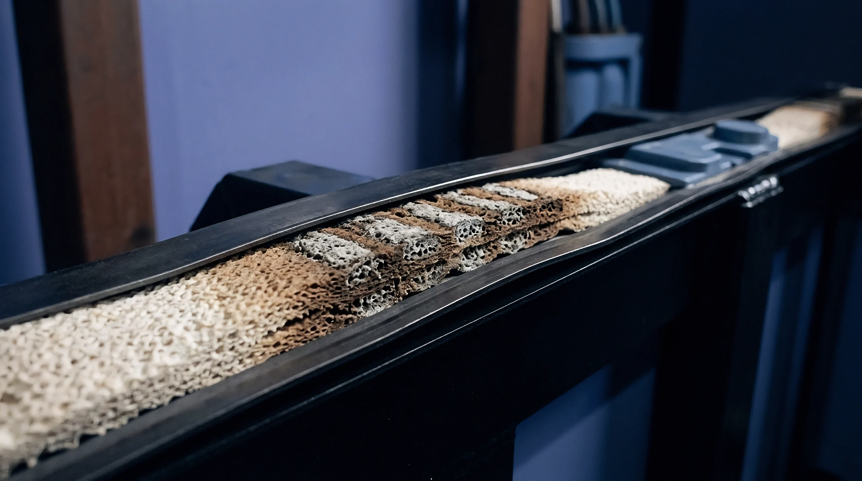
Dead lithium formation represents the primary mechanism of irreversible capacity loss resulting from sub-zero plating. During post-charge rest or subsequent discharge, plated metallic lithium attempts to strip back into ionic form or self-intercalate into underlying graphite. However, non-uniform stripping breaks metallic contact between outer lithium deposits and the conductive electrode matrix.
These electrically isolated metallic lithium fragments ~ wrapped in insulating solid electrolyte interphase shells ~ become electronically dead lithium, permanently trapped in the interphase region.
Consuming active lithium inventory to form dead lithium directly reduces discharge capacity. Simultaneously, exposed metallic surfaces continuously reduce carbonate solvents and dissolved electrolyte salts, depleting liquid electrolyte volumes within electrode pores. Liquid electrolyte drying increases transport resistance across both anode and cathode, causing rapid acceleration of cell equivalent series resistance.
Cells subjected to unmitigated sub-zero fast charging exhibit non-linear capacity knee-points, where capacity retention curves drop abruptly from gradual aging slopes into steep linear or exponential capacity loss trajectories.
Morphological evolution of metallic lithium deposits creates grave safety hazards. High local current densities and localized mechanical interphase failures favor growth of high-aspect-ratio lithium dendrites. These microscopic metallic filaments penetrate porous polymeric separators, reaching the positive electrode and establishing micro-internal short circuits.
Micro-shorts trigger localized self-discharge, localized heating, and accelerated copper current collector dissolution if local anode potential rises above 3.1 V vs Li/Cu during deep discharge events.
Structural damage extends to mechanical deformation of the electrode stack. Metallic lithium plating increases local anode thickness by 10 to 30 percent during charged states. Repeated non-uniform volume expansion and contraction generates severe mechanical stress gradients across the cell roll or pouch stack, causing separator compression, active material delamination from current collectors, and pouch gas expansion from volatile solvent reduction byproducts like ethylene and methane.
Section 8.3 of standard supply contract document C-402 voids all capacity retention guarantees if cell telemetry logs indicate more than five fast-charge events executed below minus ten degrees without active pre-heating.
Dead Lithium Accumulation and Capacity Loss
Quantifying the conversion efficiency of plated lithium into dead lithium requires rigorous cycling and analytical post-mortem evaluations. When sub-zero charging plates a total lithium mass equivalent to Q_plate, only a fraction Q_strip dissolves back during discharge. The fraction Q_intercalates slowly dissolves into graphite during rest, leaving the balance, Q_dead, permanently lost from mobile inventory.
To demonstrate the operational severity of sub-zero fast-charge erosion, consider a worked sensitivity study tracking 50Ah commercial automotive pouch cells subjected to 500 sub-zero fast-charge cycles at -15°C under four distinct charging regimes. The table below summarizes comparative degradation metrics evaluated after 500 test cycles.
| Charging Profile Strategy | Capacity Retention (%) | 1 kHz Resistance Growth (%) | Dead Lithium Mass (g/Ah) | Separator Thickness Loss (%) | Gassing Volume (cm3) |
|---|---|---|---|---|---|
| Baseline Unheated 1.5C CC-CV | 58.2 | 312 | 0.48 | 18.5 | 142 |
| Multi-Step Step-Down DC | 81.4 | 84 | 0.12 | 4.2 | 38 |
| AC Pre-Heating to +10°C then 1.5C | 93.6 | 18 | 0.01 | 0.8 | 6 |
| Anode Potential Controlled (+5mV) | 91.2 | 24 | 0.02 | 1.1 | 11 |
Data from the worked sensitivity analysis clearly demonstrates that unheated constant-current fast charging at sub-zero temperatures destroys cell utility within 500 cycles, losing over 40 percent of baseline capacity and tripling internal resistance. Internal AC pre-heating and active anode-potential-controlled charging regimes prevent severe metallic plating, preserving over 90 percent of initial capacity.

Thermal Runaway Propensity from Dendritic Microstructures
Dendritic metallic lithium accumulation drastically lowers the thermal stability threshold of fully charged cells. Clean intercalated graphite anodes react with liquid electrolyte in exothermic thermal runaway cascades starting around 120°C. Metallic lithium deposits, exhibiting extremely high specific surface areas and lower thermodynamic stability, react exothermically with carbonate solvents at temperatures as low as 70°C to 80°C.
Accelerating rate calorimetry testing of cells aged via sub-zero fast charging shows a dramatic reduction in self-heating onset temperature (T_onset). Lowering T_onset narrows the safety margin between maximum normal operational temperature and uncontrollable thermal runaway initiation. Internal micro-short circuits caused by dendritic separator penetration supply continuous low-level ohmic heating, driving localized spot temperatures up to the low-temperature thermal runaway threshold during ambient storage or operation.
Evaluating cold-climate cell durability demands incorporating four essential qualification criteria into procurement specifications:
- Maximum Permissible Voltage Relaxation Plateau Duration must not exceed 120 seconds following any sub-zero fast-charge event.
- Stripping Peak Efficiency Floor measured via dQ/dV analysis during discharge following sub-zero charging must maintain a minimum of 92 percent reversible lithium recovery.
- Thermal Runaway Onset Margin measured via accelerating rate calorimetry on sub-zero aged cells must not drop below 105°C.
- Maximum Module Thickness Swelling Boundary resulting from non-uniform metallic plating volume expansion must remain under 6 percent of nominal unaged stack thickness.
Cell sourcing contracts that omit explicit sub-zero plating diagnostic thresholds leave buyers exposed to early field failures and unpredictable warranty costs.


Coverage
Translating electrochemical plating risks into commercial protection requires structuring robust cell supply contracts and warranty schedules. Tier 1 cell manufacturers maintain strict operational limits within their product technical specifications. Standard cell datasheets typically specify charging temperature ranges between 0°C and 45°C, explicitly banning charging below 0°C or restricting low-temperature current limits to micro-rates like 0.05C.
Integrating sub-zero fast-charging capabilities into end-use products forces engineering teams to negotiate custom engineering requirements with cell suppliers. Sourcing teams must ensure technical side-agreements define exact operational envelopes, including temperature-dependent C-rate limits, pre-heating requirements, and dynamic battery management system control algorithms. Omitting precise sub-zero operating definitions from signed contract attachments allows cell suppliers to void warranty coverage whenever onboard field telemetry logs reflect low-temperature fast-charging current applications.
Field telemetry verification represents the primary legal evidence during sub-zero battery failure claims. Modern battery management systems log time-series data including individual cell voltages, pack currents, module thermistor temperatures, and software-calculated state-of-charge values. Supplier quality auditors inspect telemetry logs following field failures to identify any instance where current was applied below zero degrees without meeting validated pre-heating conditions.
Unambiguous contract definitions must state whether temperature criteria apply to ambient air temperature, pack surface thermistors, or estimated internal core temperatures.
Warranty liability allocations must account for non-linear capacity fade curves resulting from sub-zero anode plating. Standard warranty clauses guaranteeing linear capacity decay over a fixed year or cycle count fail when sub-zero plating induces sudden capacity knee-point drops. Contracts must incorporate explicit degradation acceleration clauses, specifying that capacity drop-offs exceeding three percent over any 50-cycle window trigger full supplier replacement liabilities regardless of total accumulated cycles.

Warranty Exclusion Terms in Cold Duty Specifications
Analyzing standard cell purchase agreements across major Asian and European cell suppliers highlights common exculpatory language used to defeat sub-zero warranty claims. Suppliers regularly insert clauses stating that any current applied below 0°C without prior written validation of the customer’s thermal management system invalidates all cycle-life and safety guarantees. Negotiating fair risk allocation requires embedding clear, testable qualification benchmarks directly into supply master agreements.
Quantated qualification criteria must specify the exact validation test suite used to certify sub-zero fast-charge profiles. The contract must mandate that if a battery pack follows the agreed-upon temperature-compensated charge algorithm or pre-heating protocol, any resulting capacity loss, resistance growth, or thermal safety degradation remains fully covered under standard warranty compensation schedules. Supplier approval of the battery management system charge control firmware must serve as a formal contractual milestone prior to mass production release.
Landed-cost calculations must incorporate the financial impact of warranty reserve allocations required for cold-climate product deployments. Operating products in sub-zero environments without active pack pre-heating raises field failure risk, requiring sourcing teams to inflate warranty reserve allocations from standard two percent baseline levels up to seven to ten percent of total pack landed cost. Investing upfront capital in internal AC or liquid pre-heating hardware lowers ongoing warranty reserve liabilities, delivering a net positive return on landed cost per delivered cycle over the product lifetime.
Contractual Allocation of Sub Zero Battery Failures
Allocating financial liability for sub-zero battery failures requires clear contractual separation between cell manufacturing defects, battery management system control errors, and operator abuse. Supplier liability covers intrinsic manufacturing flaws that lower plating resistance, such as negative electrode overhang misalignment, non-uniform active material coating weight, or local binder aggregation that concentrates current. Customer liability remains restricted to documented operation outside contractually approved charge profiles or deliberate override of low-temperature charge lockout limits.
Establishing incoming batch qualification protocols at receiver docks catches cell-to-cell structural variance before pack assembly. Receiving inspection programs must execute destructive tear-downs and three-electrode low-temperature characterization on statistical sample lots (ANSI/ASQ Z1.4 Inspection Level S-3) to establish baseline plating overpotential thresholds. Identifying a batch with abnormally high charge-transfer resistance or thin negative electrode overhang allows sourcing teams to reject the shipment before committing expensive pack manufacturing labor.
Finalizing a cold-climate cell procurement dossier demands establishing full traceability between electrochemical parameters, firmware controls, and legal liability terms. Sourcing practices must enforce technical compliance across every link of the supply chain, ensuring that every cell order matches strict cold-weather performance specifications validated by rigorous electrochemical test evidence.
The master supply contract rider for cold-climate energy storage systems defines sub-zero charge compliance through continuous verification of core temperature thermistor data against approved step-down current matrices. Clause 14.2 specifies that cell batches exhibiting greater than 15 percent cell-to-cell charge-transfer resistance variance at -10°C during incoming acceptance testing trigger immediate lot rejection and mandatory supplier replacement within 30 days. Integrating these strict electrochemical parameters directly into commercial purchasing terms ensures that financial risk aligns precisely with measured physics on the factory floor.