Secondary Recirculation Gas Flow Impact on Parasitic Surface Powder Accretion in Tool Steels
Secondary recirculation gas flow controls spatter condensate extraction in 1.2709 tool steel L-PBF to eliminate surface accretion and fatigue voids.

Plume
When a 400-watt laser hits a powder bed of 1.2709 maraging tool steel, local melt pool temperatures top 2,700 kelvin. Iron, nickel, and cobalt rapidly spike in vapor pressure at these temperatures, driving a vapor jet into the chamber at 10 to 50 meters per second. As this vapor column hits the cooler inert cover gas, it condenses into sub-micron oxide smoke and liquid metal droplets.
Without targeted extraction, the condensate hangs directly in the beam path ~ absorbing up to 18 percent of the laser power and scattering the rest into a wide halo. This loss of optical power drops the effective volumetric energy density at the powder bed, distorting the melt pool and causing lack-of-fusion defects deep in the tool insert substrate.
Primary delivery systems push inert argon or nitrogen horizontally across the build envelope to sweep condensate toward an exhaust duct. Standard laminar curtains, however, rarely clear the boundary layer within 5 millimeters of the active laser spot. Thermal buoyancy from the rising vapor jet easily overcomes horizontal gas streams running below 1.5 meters per second, sending condensate particles up into the upper chamber volume.
As those particles drift back down onto the freshly solidified steel track, they form parasitic micro-spatter and partially sintered clusters across critical tooling surfaces.
Laser Vapor Jet Interactions and Condensate Entrainment
Gas streams must strip out molten ejecta without blowing away un-melted powder next to the track. Tool steel grades like H13, M2, and 1.2709 carry volatile elements ~ manganese, silicon, and chromium ~ that vaporize early in the melt cycle. The resulting plume acts as a Rayleigh-scattering column that distorts the beam, pulling the focal point up by as much as 1.2 millimeters during long tool builds.
Secondary recirculation loops address this by launching auxiliary high-velocity gas jets right above the melt plane, adding horizontal momentum to keep the vapor column moving.
If secondary gas velocity drops too low, standing eddies form just downstream of the scan vector. These stationary vortices trap condensate inside the beam line for hundreds of milliseconds, increasing optical attenuation and causing rapid power fluctuations at the bed surface. Keeping the process stable requires pulling out sub-micron soot before it agglomerates past 5 micrometers in diameter, since larger clusters scatter optical wavelengths far more efficiently and disrupt energy delivery across multi-laser systems.
| Primary Velocity (m/s) | Secondary Loop Velocity (m/s) | Condensate Extraction Rate (%) | Beam Transmissivity Loss (%) | Powder Bed Shear Stress (Pa) |
|---|---|---|---|---|
| 1.0 | 0.0 | 62.4 | 14.2 | 0.08 |
| 1.5 | 2.5 | 88.7 | 5.1 | 0.22 |
| 2.0 | 4.0 | 96.1 | 1.8 | 0.48 |
| 2.5 | 5.5 | 98.3 | 0.9 | 0.85 |
| 3.0 | 7.0 | 99.1 | 0.6 | 1.34 |
Optical Window Degradation and Secondary Suction Positioning
Fume extraction relying only on top-down sweep channels cannot protect the quartz entry window from fine metallic soot. Secondary recirculation systems handle this by diverting clean inert gas to form a positive-pressure curtain across the bottom face of the entry optic, keeping sub-micron iron oxides from diffusing upward against the main flow. With secondary purge nozzles maintaining 3.0 meters per second across the glass face, window transmissivity drops by less than 0.5 percent across a 100-hour tool steel build.
Where the exhaust plenum sits determines if condensate stays airborne or falls back onto the print. Setting suction intakes too high above the bed lets heavy spatter drop back into the build envelope. Bringing nozzles down to within 12 millimeters of the melt plane catches those dense droplets, but risks localized pressure drops that suck loose powder off the bed.
Secondary recirculation manifolds fix this pressure imbalance by running high-velocity blow nozzles alongside distributed suction slots around the chamber perimeter.
Secondary gas recirculation loops operating at 4.0 meters per second maintain optical window transmissivity above 98 percent throughout 100-hour maraging steel build cycles.
Filter housing design directly affects pressure stability in secondary ductwork. As soot builds up on primary HEPA filters, system resistance climbs, dropping secondary gas velocities by up to 35 percent over 48 hours of continuous printing. Differential pressure sensors need to trigger dynamic blower adjustments to hold mass flow constant; otherwise, altered velocity profiles above the bed will cause noticeable surface roughness variations from the bottom to the top of printed inserts.
Standard primary sweeps are often expected to clear enough condensate on their own, but in high-volume tool steel printing, single-sweep setups consistently let fine particulate accumulate on laser optics, forcing operators to pause long builds for manual cleaning and recalibration.


Boundary
Gas flow right above the active powder bed determines whether metal vapor clears cleanly or powder gets scoured away. Fluid dynamics at this interface come down to boundary layer shear stress. Virgin tool steel powders atomized between 15 and 45 micrometers have a sharp fluidization limit under shear.
Push local shear past that limit, and loose powder strips off the bed, creating denudation zones along feature edges and exposing underlying solid layers to direct laser overspray.
Holding a stable boundary layer means balancing secondary jet momentum against bed fluidization limits. Gas speeds above 3.2 meters per second at 1.0 millimeter off the powder bed generate enough Bernoullian lift to dislodge fine tool steel particles. Once airborne, these particles enter the beam or land on nearby melt tracks.
Manifold geometry should therefore produce a broad velocity plateau rather than high-peak jets, keeping the condensate sweep uniform without exceeding critical wall shear values.

Bernoullian Shear Limits and Bed Denudation
Disturbing the powder layer compromises dimensional accuracy on external surfaces and internal conformal channels. In maraging tool steels, displaced powder along overhangs lets liquid metal pool, pushing down-skin roughness past typical post-machining allowances. Angling secondary recirculation nozzles acute to the build surface flattens the vertical velocity gradient, damping out dynamic pressure swings across the scan field.
Boundary layer thickness is rarely uniform on plates 300 millimeters or larger. As primary gas drags along stagnant chamber atmosphere, it slows down, thickening the boundary layer from the inlet edge over to the exhaust plenum. That spatial gradient leads to uneven cooling and variable condensate clearance across the plate.
Adding secondary injection manifolds along mid-chamber spans re-energizes the flow, keeping fluid shear forces uniform across the entire build envelope.
- Position a calibrated hot-wire anemometer array across nine distributed points on the build plate at a fixed height of 2.0 millimeters.
- Turn on primary gas circulation and raise blower frequency until the average velocity across all nine sensors hits 1.5 meters per second.
- Ramp up the secondary recirculation loop in 5 percent blower power increments, recording local shear stress changes across the bed.
- Examine un-melted powder beds with optical profilometry to check for particle movement or trenching along the inlet vector.
- Set secondary blower controls to the highest velocity step that shows zero particle movement across all nine test points.

Pressure Differential Balancing across Wide Build Envelopes
Static pressure imbalances between supply manifolds and exhaust plenums trigger unpredictable cross-bed recirculation currents. If exhaust suction pulls harder than supply delivery, overhead chamber gas gets drawn down into the build zone, creating turbulent vortices that mix fine soot back in. Over-pressurizing the supply side does the opposite, creating high-pressure zones that deflect primary gas streams upward and let condensate drop onto peripheral powder.
Secondary channels need active pressure tracking across both supply and return headers. Holding differential pressure within 15 pascals via dedicated transducers suppresses cross-flow eddies across the build plane. That pressure stability keeps spatter moving along predictable paths into exhaust collectors rather than landing at random on critical tool sealing surfaces.
Gas flow vectors aligned parallel to the primary laser raster pattern yield lower condensate redeposition rates than orthogonal flow orientations.
Pressure gradients across the chamber also interfere with thermal uniformity in the substrate. Unbalanced gas recirculation causes uneven convective cooling across the build plate, creating thermal gradients that worsen macro-warpage in high-carbon tool steels like H13. Matching secondary recirculation gas to platform temperature with in-line pre-heaters mitigates thermal shock and residual stress buildup during long print runs.
Secondary gas vectors ultimately have to balance clear condensate removal against bed displacement, keeping local gas velocity right below the powder fluidization threshold.

Accretion
Parasitic accretion happens when semi-molten spatter, heat-affected powder, and metallic condensate stick to non-melted sidewalls. During high-power passes, thermal radiation extending past the melt pool heats adjacent loose grains above their solidus temperature. These softened particles fuse onto vertical and angled surfaces, forming a rough crust.
Secondary gas recirculation directly controls how much heat-affected spatter remains in the surrounding atmosphere, setting the accretion rate.
In tool steel components with internal conformal cooling passages, unchecked accretion degrades performance quickly. Accreted powder roughens channel walls, increasing fluid friction and pressure drop while generating local hotspots during injection molding cycles. Secondary gas loops must clear spatter out of channel openings before particles settle onto hot overhang edges during scanning.
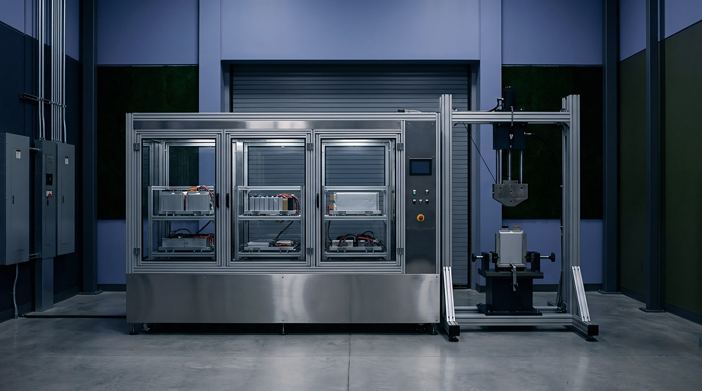
Mechanisms of Partial Particle Fusion and Spatter Attachment
Molten droplets thrown from the pool carry heat and thin oxide coatings. If gas flow is too weak to clear them quickly, their outer shells stay liquid in mid-air. When they land on solidified steel contours, they weld in place, forming irregular metallic nodes from 50 to 200 micrometers across.
These nodes act as stress risers, reducing the fatigue life of die-casting inserts under cyclic thermal loading.
Sub-micron condensate that misses extraction drops onto un-melted powder beds, forming an oxide crust. As the laser sweeps over contaminated areas on subsequent layers, that oxide layer prevents full melt pool wetting ~ leading to balling, micro-voids, and heavy accretion along contour lines. Sweeping the bed with high-velocity secondary gas removes condensate before it can settle into continuous oxide films.
| Flow Field Position | Secondary Flow Rate (m/s) | Accretion Thickness (µm) | Surface Roughness Ra (µm) | Surface Roughness Rz (µm) | Sub-surface Porosity (%) |
|---|---|---|---|---|---|
| Inlet Proximity | 4.5 | 32 | 6.8 | 38.4 | 0.04 |
| Mid-Chamber Center | 3.8 | 48 | 9.2 | 52.1 | 0.09 |
| Exhaust Proximity | 2.1 | 115 | 18.4 | 96.7 | 0.38 |
| Stagnation Vortex Zone | 0.8 | 210 | 31.5 | 165.2 | 1.12 |

Conformal Channel Wall Roughness and Geometry Degradation
Conformal channel performance relies on holding target CAD dimensions and smooth internal walls. When secondary recirculation fails to clear condensate from internal cavities, accreted powder can restrict effective flow area by up to 25 percent in 6-millimeter passages. The resulting micro-roughness disrupts smooth coolant flow, triggering localized cavitation erosion under high-pressure water cooling.
Down-skin overhangs inside channels are especially vulnerable to accretion because heat dissipates poorly into surrounding powder. Hot gas trapped under overhangs accelerates sintering of adjacent loose grains. Angling secondary injection nozzles directly into open channel geometry flushes out stagnant gas, preventing non-melted powder from sintering to overhang boundaries.
- Cooling Flow Restriction where accreted powder chokes internal passages, raising coolant pressure drop across injection mold inserts.
- Thermal Fatigue Cracking initiated by micro-notches at the boundary between accreted spatter nodes and the solid tool steel wall.
- Corrosion Pit Initiation in stagnant crevices underneath partially fused powder grains exposed to cooling water.
- Dimensional Out-of-Tolerance on precision cavity faces, forcing extra post-process CNC sinker EDM or manual polishing.
- Optical Sensor Blindness caused by laser power scattering off rough, accreted surface features during in-situ process monitoring.
A secondary gas velocity deficit below 1.5 meters per second increases vertical wall accretion thickness on H13 tool steel inserts from 35 micrometers to 185 micrometers.
How the scan vector aligns with gas flow direction heavily influences accretion behavior. Scanning into oncoming gas pushes condensate away from un-melted powder, keeping surface contamination low. Scanning co-directional with the gas stream drags the condensate cloud right along the melt track, accelerating particle accretion onto nearby solid walls.
Dropping secondary recirculation velocity below tolerance leads to heavy surface accretion that drives up machining costs, increases scrap rates, and shortens the thermal fatigue life of finished inserts.


Metallurgy
Microstructural integrity in 1.2709 maraging and H13 tool steels relies on keeping alloy chemistry uniform and oxygen levels low during melting. Accreted particles and re-entrained condensate drag non-metallic oxide inclusions into the pool. Sub-micron chromium-manganese spinels (Cr2O3, MnFe2O4) serve as nucleation sites for gas pores and micro-cracks during solidification.
Secondary gas loops pull these light oxides away before the trailing edge of the liquid pool can engulf them.
Sub-surface porosity in printed tool steels often traces back to gas trapped inside agglomerated condensate. When the laser strikes an accreted lump of soot, trapped argon expands violently, leaving spherical pores from 10 to 50 micrometers across. If oxide films line the inner pore walls, even post-build Direct Energy Deposition or Hot Isostatic Pressing (HIP) will fail to close them completely, degrading impact toughness in the finished component.

Does Cross-Flow Recirculation Eliminate Heat-Affected Condensate?
High-velocity cross-flow recirculation slashes heat-affected condensate in the laser zone, but total removal is bound by fluid dynamic realities. Extracting every bit of sub-micron soot is constrained by gas diffusion within the viscous sub-layer right at the powder bed. Condensate generated within 200 micrometers of the melt pool surface sees extreme thermal gradients, solidifying before horizontal gas momentum can drag it clear of the track.
Condensate that avoids extraction drops back onto lower layers, changing local thermal conductivity. In maraging steels, contaminated regions retain localized austenite even after standard solution heat treatment and aging (520 degrees Celsius for 6 hours). These retained austenite islands lower local yield strength and cause hardness variations across injection mold cavity faces, shifting from 48 HRC in contaminated spots to 56 HRC in clean zones.
Standard specifications under ASTM F3055 require internal channel surface defect depth to remain below 50 micrometers for fatigue-critical tooling applications.
Phase transformations across multi-pass builds are highly sensitive to oxygen pickup from stagnant gas flow. Tool steels melted under weak secondary gas sweep absorb up to 350 parts per million of dissolved oxygen, compared to 80 parts per million under optimized flow. Higher oxygen content accelerates burn-off of vanadium and titanium, altering precipitation hardening behavior during post-print heat treatment.
It remains unclear how secondary flow profiles behave in high-power multi-laser systems, where multiple vapor plumes produce complex shockwaves and overlapping condensate fields inside a single build chamber.


Inspection
Verifying secondary gas recirculation performance takes continuous monitoring of flow fields and surface quality. Thermal anemometry arrays map horizontal and vertical gas velocity profiles across the build platform before printing begins. High-speed optical imaging with narrow-band illumination captures spatter trajectories, letting engineers map particle movement and pinpoint low-velocity dead zones inside the chamber.
In-situ monitoring setups combine photodiodes and pyrometers to track plume intensity and flicker frequency, where thermal instabilities correlate directly with drops in gas extraction performance. Logging optical transmissivity in real time with auxiliary laser probes detects window contamination immediately, triggering automated pauses before process parameters drift out of specification.
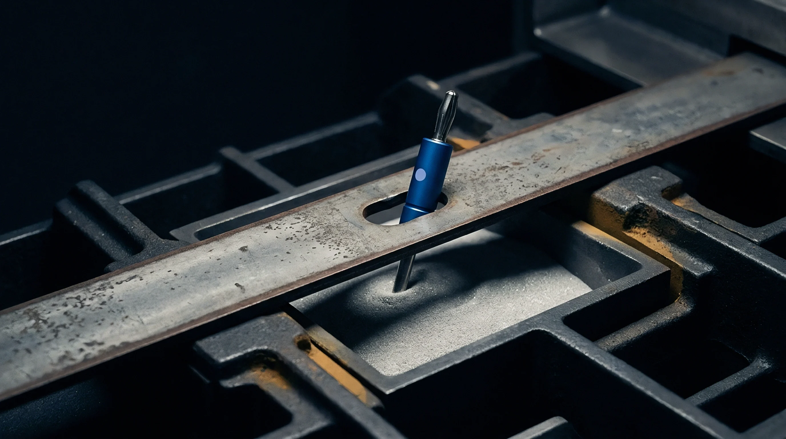
Anemometry Mapping and Spatter Trajectory Tracking
Calibrating secondary manifold performance requires grid-mapping gas velocities across multiple z-heights in the chamber. Multi-axis hot-wire sensors measure turbulence intensity, which has to stay below 8 percent to prevent chaotic spatter scattering over the bed. High-speed camera footage captured at 10,000 frames per second tracks spatter velocity vectors to verify whether extraction channels are actually pulling heavy ejecta into collection plenums.
Post-build verification of printed inserts relies on micro-computed tomography (micro-CT) scanning to evaluate conformal channel geometry and measure accretion volume. High-resolution X-ray tomography maps internal surface roughness, wall thinning, and sub-surface porosity without destroying expensive components. On external surfaces, optical white-light interferometry measures roughness parameters (Ra, Rz, Sa) to confirm uniform gas flow across the build plate.
- Velocity Field Uniformity measuring gas speed standard deviation across a 9-point grid to keep variation under 5 percent.
- Turbulence Intensity Limit confirming local flow fluctuations stay below 8 percent near active laser scan paths.
- Optical Window Transmissivity Rate tracking light attenuation through the entry optic to enforce mandatory cleaning thresholds.
- Internal Channel Roughness Cap holding Ra values inside conformal passages under 10 micrometers based on micro-CT evaluation.
- Sub-Surface Porosity Threshold verifying bulk density of the printed tool steel exceeds 99.8 percent via Archimedes density testing.

Micro-CT Scanning and Internal Roughness Metrics
Non-destructive micro-CT scanning yields three-dimensional spatial maps of accretion inside complex channels. Software algorithms separate cavity voids from solid steel, measuring local wall deviations against original CAD models. Areas showing accretion buildup over 75 micrometers point directly to gas flow dead zones that call for manifold redesign or flow adjustments.
Destructive metallographic sectioning validates NDT findings during initial qualification. Optical and scanning electron microscopy (SEM) examine cross-sections of vertical walls and overhangs, checking grain structure, phase distribution, and oxide inclusion density at the boundary between solid parent steel and accreted powder nodes.
Procurement contracts should make machine acceptance contingent on documented velocity uniformity within plus or minus 0.3 meters per second across the build surface, backed by micro-CT proof of internal channel roughness below specified limits.


Liability
Purchasing agreements for metal additive systems often blur true performance limits for gas recirculation. Machine OEMs typically market nominal blower capacities measured in an empty chamber at room temperature. During actual tool steel production runs running over 100 hours at elevated bed temperatures, thermal expansion of chamber gas and HEPA filter loading drop effective flow velocities substantially.
Sourcing engineers need strict performance guarantees written into equipment purchase orders to avoid operational disputes later.
Tooling buyers face serious financial exposure when accretion causes premature insert failure during injection molding or die casting. If a conformal cooling channel fails from stress risers created by accreted spatter, line downtime can easily run thousands of dollars an hour. Mitigating that risk requires establishing explicit legal and technical boundaries of responsibility between material suppliers, machine OEMs, and contract printers.

Equipment OEM Process Guarantees Vs Delivered Performance
Equipment specs should mandate verifiable flow performance rather than theoretical blower output. Contracts need to spell out secondary recirculation parameters under fully loaded operating conditions ~ including maximum pressure drop limits across filter units before auto-cleaning kicks in. Suppliers that fail cross-chamber flow metrics should be required to retrofit manifold hardware or accept contractual non-acceptance penalties.
Inserts built for high-pressure die casting require zero-defect sub-surface zones to withstand severe thermal shock. Contracts should lay out sampling protocols based on ISO 2859-1 standards, specifying non-destructive micro-CT inspection of critical internal channels on every lot. Rejections driven by accretion or spatter-induced porosity fall back on supplier non-conformance liabilities if process boundaries are clearly set in the master agreement.

Tooling Scrap Rate Allocation and NRE Risk Seams
Non-recurring engineering (NRE) costs for complex tool steel inserts frequently outpace material costs. When a multi-day build gets aborted at 90 percent completion because soot accumulated on optical windows, who pays for lost machine time and scrapped powder comes down to contract terms. Dumping process drift risk entirely onto contract manufacturers without defining maintenance protocols just invites commercial disputes.
Setting clear liability boundaries requires logging real-time gas flow data directly into the build quality dossier. If recorded secondary velocities drop below qualified thresholds during a print, liability shifts to the machine operator or maintenance team. If flow metrics stay strictly within range throughout the build, microstructural defects fall back on powder feedstock quality or laser optic calibration.
Calculating landed costs for additive tool inserts requires factoring in potential scrap rates from degraded gas flow. An insert design with a nominal runtime cost of 4,000 dollars easily doubles in effective unit price if weak extraction pushes scrap rates past 15 percent. Amortizing high-performance secondary manifolds into initial machine NRE delivers substantial net savings over multi-year runs by holding yields above 98 percent.
Risk allocation in AM tooling procurement depends on precise technical metrics, not generic quality statements. Defining secondary gas performance limits across equipment purchase orders, raw material specs, and supply contracts ensures buyers do not absorb the financial burden of process-induced metallurgical defects.