Sulfide Solid Electrolyte Viscoplasticity and Interface Contact Mechanics
Sulfide solid-state cells require continuous external stack pressure between 5 and 10 MPa to overcome viscoplastic voiding and maintain intimate interface contact.
Yield
Inorganic solid electrolytes based on thiophosphates are significantly more compliant than oxide ceramics, which fundamentally changes how solid-state cell stacks respond to mechanical load. Cold-compacting lithium argyrodite (Li6PS5Cl) or beta-lithium thiophosphate (beta-Li3PS4) powder at room temperature yields dense separator pellets through localized particle deformation, bypassing high-temperature sintering altogether. Solid-state cell architectures depend on this room-temperature compaction to build continuous ionic pathways across the electrolyte grains, meaning applied housing loads deform both the sulfide matrix and the metallic lithium anode simultaneously.
Room-temperature shear modulus values for sulfide solid electrolytes fall between 7 GPa and 12 GPa, with bulk modulus values spanning 15 GPa to 25 GPa. By comparison, metallic lithium has a room-temperature shear modulus of roughly 3.4 GPa and yields under uniaxial tension at just 0.5 MPa to 1.2 MPa. When external compressive loads reach the stack, the soft metallic anode flows plastically long before the sulfide separator approaches its own yield point, concentrating shear stresses along adjacent grain boundaries.

Elasto-Plastic Constitutive Properties of Thiophosphate Electrolytes
Separator pellets pressed from Li6PS5Cl have an elastic modulus near 20 GPa and a hardness of 1.1 GPa, making them roughly five times softer than oxide conductors like garnet Li7La3Zr2O12. Uniaxial cold pressing between 200 MPa and 400 MPa densifies these sulfide powders beyond 92 percent of their theoretical limit, bringing down interparticle boundary resistance. When local shear stresses climb past 150 MPa, plastic yield occurs within the thiophosphate particles via dislocation glide and grain rearrangement.
Because bulk densification sets the baseline ionic impedance, residual pores in the electrolyte layer act as local stress concentrators. Compaction runs that miss full density leave behind micro-void networks, which then serve as open paths for lithium extrusion during high-rate charging.

Interfacial Stress Concentration and Metallic Lithium Plastic Flow
Anode contact surfaces face complex multi-axial stress fields during electrodeposition. Applied stack pressure drives the softer lithium into microscopic asperities across the harder sulfide separator face, forcing metal into open surface pores. If the local current density outpaces plastic relaxation, hydrostatic pressure in the lithium can climb past 20 MPa, initiating intergranular micro-cracks in the thiophosphate pellet.
Even with the moderate mechanical compliance of sulfide electrolytes, surface defects produce sharp stress spikes. The surface roughness profile determines whether the lithium yields evenly or bunches stress within microscopic troughs. Lapping the electrolyte below a center-line average roughness of 50 nanometers lowers these stress peaks by roughly an order of magnitude compared to raw cold-pressed pellets.
Uncompressed sulfide electrolyte matrices retaining three percent internal porosity exhibit localized current focusing that accelerates dendrite penetration through grain boundaries at current densities above 1.5 mA/cm2.
Uneven yielding at the metal-electrolyte boundary disrupts uniform ionic flux across the cell. Without consistent yield behavior across the full interface, localized dendrite growth and short circuits will degrade the cell well before it reaches two hundred deep discharge cycles.
- Interfacial Delamination ~ Localized separation at the anode surface caused by asymmetric mechanical stress during stripping operations, leaving non-conductive gaps across active sites.
- Asperity Creep Voiding ~ Vacancy condensation at microscopic contact asperities where applied stack pressure drops below the dynamic yield threshold of metallic lithium.
- Plastic Lithium Extrusion ~ Ingress of solid metallic lithium into open separator porosity under localized pressure gradients exceeding 15 MPa.
- Local Stress Microcracking ~ Transgranular fracture through the sulfide electrolyte separator driven by concentrated mechanical loads at rough surface contact points.


Contact
Micro-scale roughness prevents true planar mating across solid-solid electrochemical boundaries. Under moderate mechanical loads, the real contact area is only a fraction of the geometric footprint, forcing lithium ions through isolated contact points and creating severe constriction resistance. Standard constriction models treat these contact points as narrow channels that choke both electrical and ionic potential fields.
Greenwood-Williamson contact models illustrate how elastic and plastic deformation dictate true contact area over rough topographies. Sulfide electrolytes interface with lithium foil across an array of micro-contacts defined by the surface finish. Raising stack pressure forces existing asperities into plastic deformation while creating new contact points, broadening the active transport area and lowering interface resistance.
Micro-Contact Topography and Constriction Resistance
At stack pressures below 2 MPa, constriction resistance at the solid electrolyte boundary dominates total cell impedance. As ionic flux lines converge into discrete micro-contacts with typical radii between 0.2 micrometers and 2.5 micrometers, local effective resistance climbs by a factor of 5 to 50 over planar bulk values.
Constriction resistance governs low-pressure interface transport, where elastic spring-back readily breaks contact. Polishing the electrolyte surface or adding a compliant interlayer can push real contact past 80 percent of geometric area under moderate loads. Annealing near the glass transition temperature of sulfide glasses similarly improves contact by encouraging surface reflow.
| Electrolyte Chemistry | Young’s Modulus (GPa) | Shear Modulus (GPa) | Hardness (GPa) | Real Contact Ratio at 5 MPa (%) | Critical Current Density (mA/cm2) |
|---|---|---|---|---|---|
| Li6PS5Cl Argyrodite | 21.5 | 8.2 | 1.10 | 68 | 3.5 |
| beta-Li3PS4 Glass-Ceramic | 18.0 | 6.8 | 0.85 | 74 | 2.8 |
| Li10GeP2S12 (LGPS) | 24.0 | 9.1 | 1.35 | 62 | 4.2 |
| Li7P3S11 Glass-Ceramic | 16.5 | 6.2 | 0.75 | 81 | 2.2 |
Void Nucleation Dynamics during Electro-Chemo-Mechanical Cycling
During high-rate stripping, lithium atoms leave the interface faster than plastic flow or self-diffusion can replace them. Vacancies coalesce at active micro-contacts, opening nanoscale voids that separate the anode from the separator. This vacancy condensation shrinks the true contact area during discharge, driving current densities at the remaining contact points toward critical failure levels.
The critical current density for void formation scales non-linearly with stack pressure. Increasing external compression from 1 MPa to 8 MPa raises the sustainable stripping limit from 0.5 mA/cm2 to over 4.0 mA/cm2 without degrading the interface, as higher pressure drives fresh lithium directly into opening vacancy sites.
An external stack pressure of 5 MPa maintains real solid-state contact area above 65 percent during discharge rates up to 3.0 mA/cm2 at room temperature.
Managing the interface requires balancing external stack pressure against the mechanical strain limits of the separator, ideally without resorting to oversized compression hardware that penalizes pack density.
- Profile Surface Roughness ~ Measure arithmetic average roughness and mean peak-to-valley height using optical profilometry on every electrolyte batch prior to cell winding or stacking.
- Determine Yield Thresholds ~ Measure target anode yield point under multi-axial compressive loads matching expected cell temperature operating windows.
- Calculate Constriction Factors ~ Establish baseline micro-contact distribution maps to model local ionic flux concentration under minimum expected operating pressures.
- Verify Vacuum Mating ~ Execute solid interface assembly under vacuum conditions below 1 Pa to prevent gas entrapment inside microscopic surface valleys.


Flow
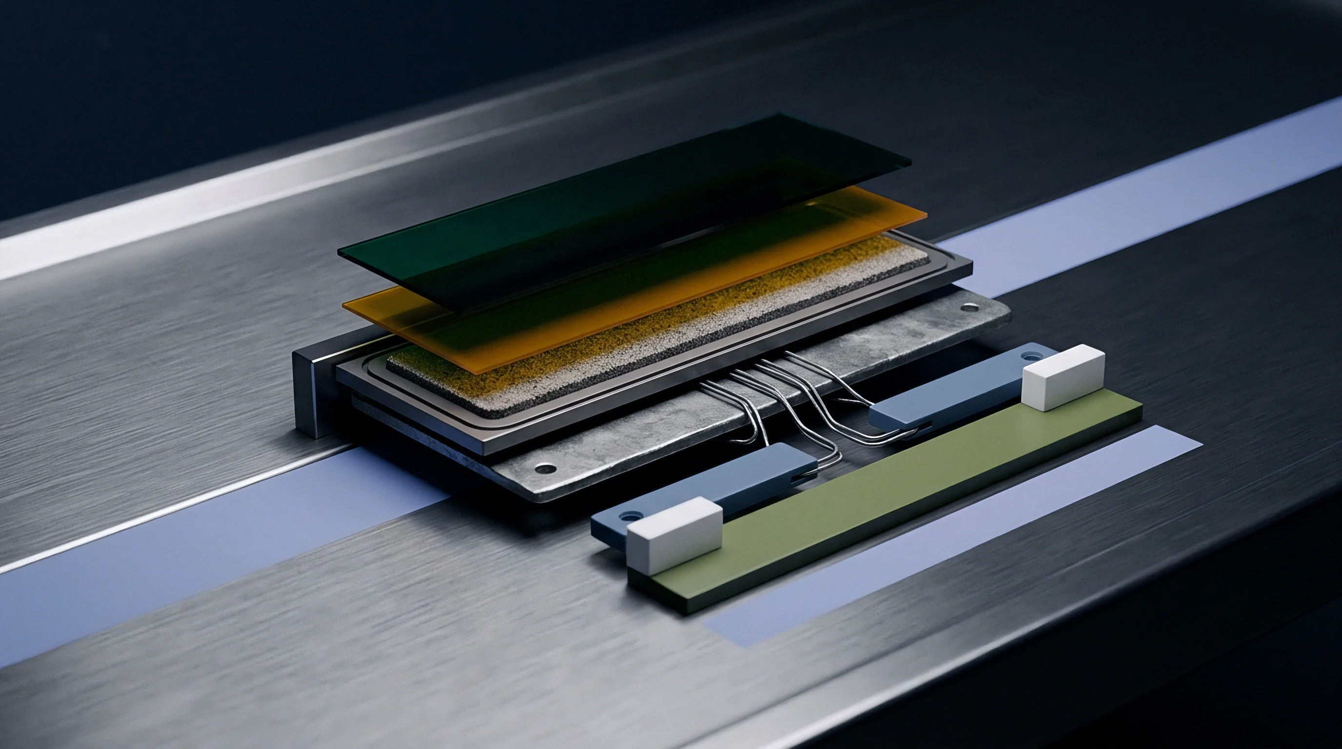
Time-dependent deformation governs how solid electrolyte interfaces hold up over extended cycling. Both lithium metal and thiophosphate electrolytes undergo measurable viscous flow under sustained compressive loads at ambient operating temperatures, displaying viscoplastic strain behavior where stress rate, strain rate, and temperature collectively drive shape changes.
Because metallic lithium operates at a high homologous temperature at room conditions (T/Tm = 0.65 at 25 degrees Celsius), creep occurs primarily through dislocation climb and grain boundary sliding. Sulfide electrolytes deform over time as their glassy or nanocrystalline networks relax under load, causing initial assembly pressures to decay when held at a fixed volume.
Time-Dependent Strain Kinetics under Constrained Loading
Lithium undergoes rapid primary creep upon initial loading before settling into steady-state secondary creep within a few hours. This secondary regime follows power-law kinetics with a stress exponent between 3.2 and 6.6. These high creep rates allow the soft lithium to flow into surface irregularities on the separator, closing micro-gaps without requiring massive assembly pressures.
Operating temperature strongly influences this flow behavior. Lowering the cell temperature to 0 degrees Celsius reduces lithium creep rates by two orders of magnitude compared to 45 degrees Celsius, making interfacial voiding far more severe during cold-weather discharge.
Stress Relaxation Profiles and Interfacial Void Healing
Rigid, fixed-displacement enclosures cause stack pressure to drop logarithmically over time as cell materials relax. A sulfide stack pre-loaded to 10 MPa can lose 20 to 35 percent of its initial clamping force within 500 operating hours unless the housing incorporates compliance. This loss of load lowers real contact area, raising interfacial impedance and accelerating voiding during subsequent stripping steps.
When current ceases, external pressure can push metallic lithium back into vacant sites. This void healing depends on the rest duration, local hydrostatic stress, and temperature-dependent diffusion rates. Brief rest periods between high-current discharge pulses allow viscoplastic flow to refill voids, restoring the contact footprint before the next charge cycle starts.
Do Dynamic Compression Cycles Prevent Interfacial Void Growth?
Varying the applied load during cycle transitions alters void kinetics by adjusting local hydrostatic pressure across the anode face. Active hydraulic or piezoelectric systems can tune pressure to match volume expansion across states of charge, keeping stress above the voiding limit during both charge and discharge. Passive spring systems aim for the same result by using calibrated spring rates to buffer phase-change expansion.
Lithium shuttling continually shifts stack thickness, with every 10 micrometers of plated lithium adding roughly 10 micrometers per layer and driving sharp load spikes in rigid enclosures. Structural compliance keeps these pressure spikes from fracturing the separator on charge while preventing the clamping load from dropping below the voiding threshold during discharge.
- Mount the sulfide electrolyte pellet inside a temperature-controlled hermetic test cell equipped with an inline quartz load transducer and dual LVDT displacement monitors.
- Apply a baseline uniaxial compressive stress of 10.0 MPa at a controlled loading rate of 0.5 MPa/s using a calibrated micro-servo actuator.
- Lock the axial displacement fixtures to establish continuous fixed-strain conditions across the electrolyte sample.
- Record stress decay continuously over a 240-hour test duration at controlled ambient temperatures of -10, 25, and 60 degrees Celsius.
- Extract power-law stress relaxation parameters and calculate effective viscoplastic relaxation time constants for each operational temperature point.
Solid lithium creeps rapidly enough under 5 MPa stack pressure at room temperature to heal micro-scale interfacial voids within thirty minutes of rest.
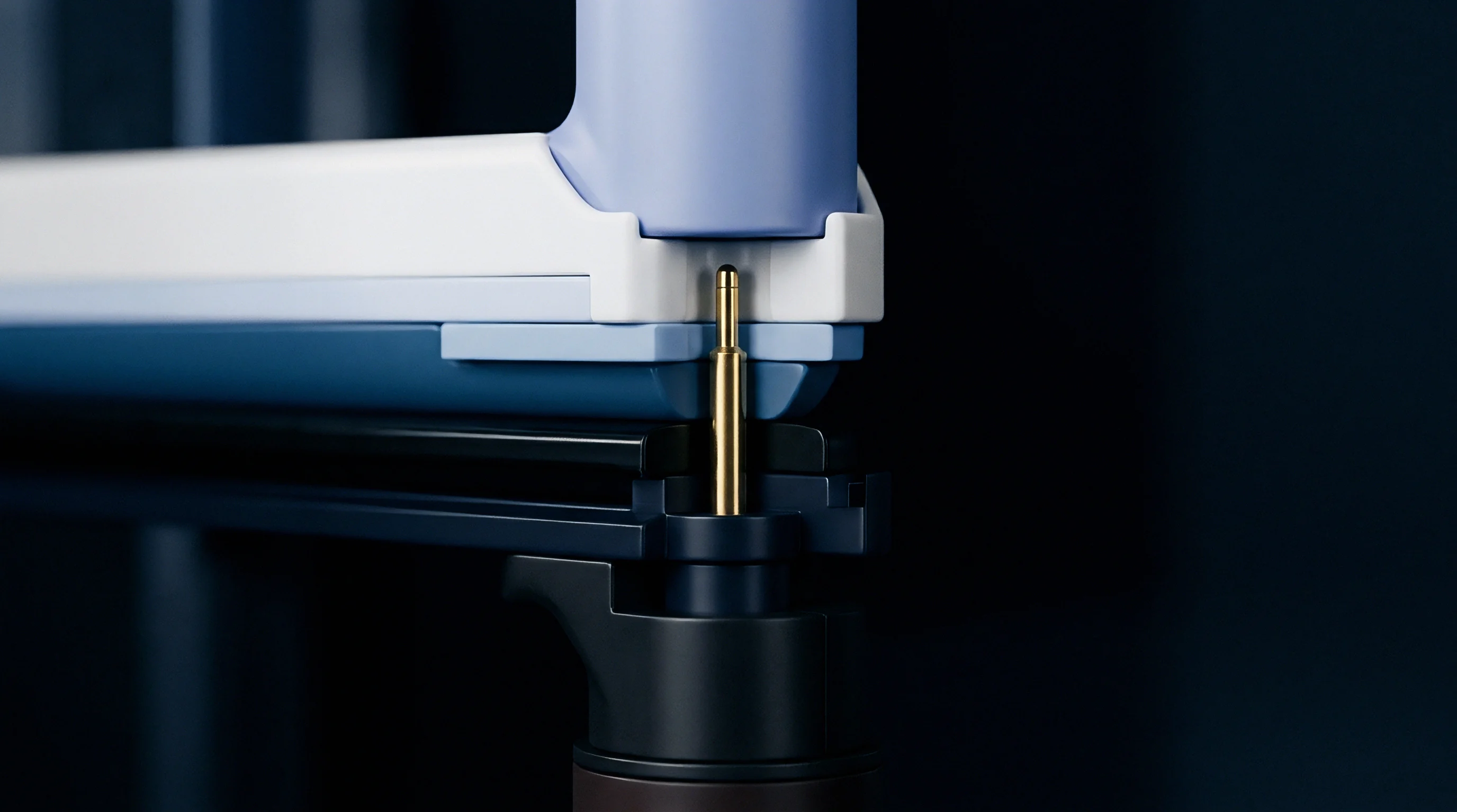
Clamp
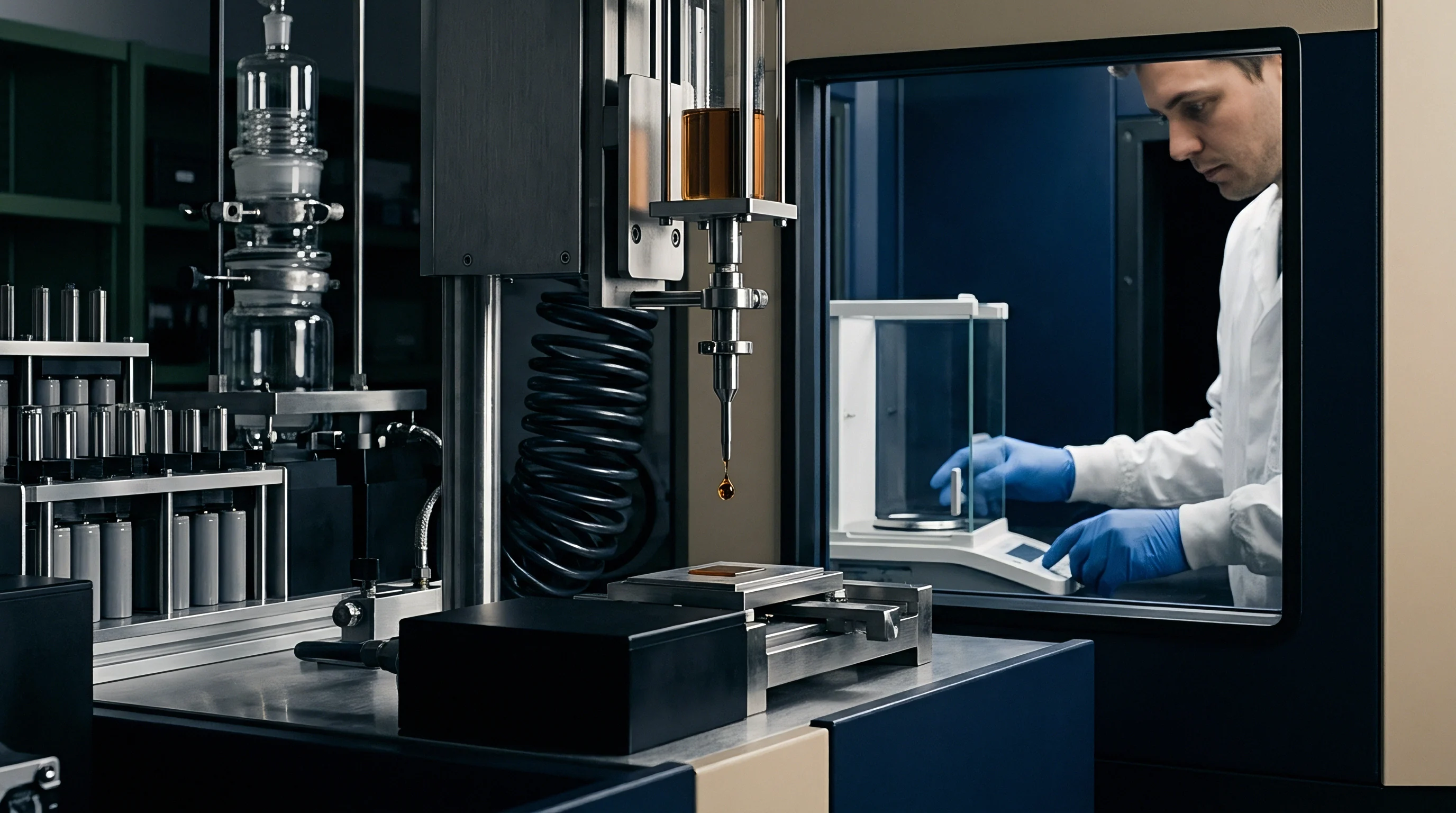
Module packaging must translate cell-level pressure targets into practical hardware. Sulfide solid-state cells require continuous external compression between 3 MPa and 15 MPa throughout their operational life to maintain interfacial contact. Sizing the springs, heavy endplates, and tension tie-rods needed to deliver this load adds dead mass and volume, cutting directly into pack-level energy density.
Pouch, prismatic, and cylindrical formats each introduce different mechanical constraints. Pouch cells allow direct surface loading with flat compression plates, though edge seals must withstand continuous lateral stress. Prismatic cans handle internal loads better, but their thin walls complicate high-pressure retention without bulging.
| Compression System Type | Operational Pressure Range (MPa) | Spring Rate Drift per 1000 Cycles (%) | Mass Penalty (% of Module Mass) | Operating Temperature Limits (deg C) | Relative Unit Cost |
|---|---|---|---|---|---|
| Belleville Washer Stack with Tie-Rods | 5.0 – 15.0 | < 2.5 | 8.5 – 12.0 | -40 to 120 | Baseline (1.0x) |
| Microcellular Silicone Foam Insert | 2.0 – 6.0 | 12.0 – 18.0 | 2.1 – 4.0 | -30 to 80 | 0.45x |
| Ultra-High-Density Polyurethane Foam | 1.5 – 4.5 | 22.0 – 35.0 | 1.8 – 3.2 | -20 to 60 | 0.30x |
| Closed-Loop Active Piezoelectric Actuator | 2.0 – 20.0 | < 1.0 | 14.0 – 18.0 | -20 to 70 | 4.80x |

Retention Mechanics across Module and Pack Formats
Belleville washers arranged in series and parallel provide high spring constants in tight axial spaces, making them standard for rigid tie-rod assemblies. The tie-rods hold compression plates firmly against the cell faces, absorbing pouch expansion during plating while sustaining baseline pressure during stripping. Using stainless steel or titanium for the tie-rods prevents long-term creep elongation under load.
While Belleville washer arrangements hold baseline loads as pouch cells expand against tie-rod tension, microcellular elastomeric foams exhibit heavy stress relaxation over time. Polyurethane pads, for instance, lose up to 30 percent of their restoring force over 500 thermal cycles between -20 and 60 degrees Celsius, leaving sulfide interfaces vulnerable to contact loss.
Cylindrical designs use the rigid outer casing to generate radial restraint. As the jelly-roll expands during lithium deposition, internal hoop stress compresses the solid electrolyte particles together without requiring external endplates. However, depositing uniform, crack-free sulfide coatings on curved mandrels remains difficult in high-volume production.
A module enclosure incorporating high-strength tie-rods and series-stacked Belleville washers maintains set stack pressure within four percent of nominal limits across 1200 full charge-discharge cycles.
Interfacial short-circuit disputes typically center on whether failure originated from internal cell degradation or from external module hardware failing to maintain required planar tolerances across temperature transitions.
- Calibrate Load Cell Fixtures ~ Validate axial compression test benches using certified multi-axis load transducers before measuring cell stack pressure profiles.
- Verify Parallelism Tolerances ~ Enforce strict endplate surface parallelism within 0.05 millimeters across the full active area to prevent localized crushing loads.
- Map Thermal Expansion Factors ~ Calculate differential thermal expansion between steel tie-rods, aluminum endplates, and solid electrolyte stacks across the complete vehicle thermal spec.
- Audit Belleville Spring Sets ~ Perform load-deflection hysteresis testing on all spring washer lots to guarantee uniform restoring forces under dynamic load cycles.


Margin
Sourcing agreements for solid-state cells must clearly divide mechanical pressure responsibilities among the cell supplier, module builder, and pack integrator. Because thiophosphate performance depends directly on delivered load, published cycle life and critical current density figures mean little without defined stack pressure limits, parallelism tolerances, and stress-relaxation envelopes.
These mechanical boundaries directly govern tooling NRE, warranty allocations, and incoming quality thresholds. If a pack enclosure allows compression to slip below contractual minimums, liability for subsequent voiding or dendritic shorting shifts away from the cell maker. Tracking internal pressure through BMS telemetry is therefore becoming a standard diagnostic requirement.
Mechanical Stack-Up Tolerances and Pressure Decay Boundaries
A 12-cell pouch module running at a target pressure of 8.0 MPa illustrates the stack-up challenge. If active stack thickness expands by 0.24 millimeters per cell at full charge, the module sees 2.88 millimeters of total linear expansion. With rigid steel tie-rods rated at an axial stiffness of 45 kN/mm, that 2.88-millimeter displacement drives internal pressure from 8.0 MPa up to 14.2 MPa at 100 percent state of charge.
Such high loads raise local shear stress and increase the chance of separator edge punctures. Thermal expansion mismatches compound the issue: aluminum endplates expand faster than steel tie-rods between 25 degrees Celsius and 50 degrees Celsius, relaxing rod tension and dropping low-SOC pressure from 8.0 MPa to 4.1 MPa. Any drop below 5.0 MPa accelerates voiding during high-rate discharge.
Standard supply agreements require the pack enclosure to maintain stack pressure within plus or minus 15 percent of target baseline over a temperature window from -20 to 55 degrees Celsius.
Warranty arbitration depends on clear boundary lines separating electrochemical degradation from external pressure loss. Supply contracts enforce these mechanical limits through standardized pre-delivery qualification testing.
Section 14.3 of standardized solid-state cell integration specifications voids vendor cycle-life performance guarantees upon any recorded drop in external clamp compression below 4.5 MPa during discharge operations above 2.0 mA/cm2.