Electrolytic Additive Passivation Mechanics on Reconstructed Surface Interphases of High Nickel Cathode Systems
Sacrificial electrolyte additives stabilize high-nickel cathode surface phases by forming inorganic passivation films that inhibit nickel reduction and oxygen gas release.


Phase

Structural Transformation at High Nickel Surface Boundaries
High-nickel cathode active materials, including LiNi0.8Mn0.1Co0.1O2 and nickel-rich aluminum-doped formulations, become thermodynamically unstable at oxidation states above 4.15 volts versus lithium metal. Extracting lithium ions beyond seventy percent of theoretical capacity shifts surface nickel cations from trivalent to highly reactive tetravalent states, which spontaneously reduce at elevated temperatures and strip electrons from surrounding lattice oxygen anions.
This oxidation releases singlet oxygen species directly into the liquid electrolyte. At the same time, the rhombohedral crystal lattice at the particle surface collapses into a disordered, electrochemically inactive rock-salt structure that acts as an insulating barrier to lithium ion diffusion.
Lattice oxygen escapes rapidly during this phase breakdown.
As a consequence, surface impedance rises across the active particle boundary.
The thickness of this reconstructed surface zone depends directly on upper cut-off voltage and nickel stoichiometry. When nickel content exceeds ninety mole percent, this layer penetrates up to ten nanometers deep into the bulk grain within fifty charge cycles, allowing transition metal cations ~ particularly divalent nickel ~ to migrate from cathode lattice sites into the electrolyte solution.

Cation Migration and Lattice Collapse Kinetics
Dissolved transition metal ions travel across the porous separator to deposit on the graphite anode surface. This cross-contamination breaks down the solid electrolyte interphase on the negative electrode, consuming lithium continuously and driving gas formation. High-resolution transmission electron microscopy shows that planar gliding along active slip planes triggers localized microcracking within secondary spherical agglomerates.
These microcracks expose unpassivated particle interiors to direct contact with the electrolyte.
Electrolyte penetration into these fresh microcracks triggers further surface reduction cascades, compounding capacity loss over extended cycling. Managing this boundary instability requires precise selection of sacrificial additives during cell manufacturing.
Cathodes with higher nickel concentrations require thicker protective passivation films to handle elevated operating voltages without triggering runaway lattice collapse.


Solute
Sacrificial Additive Kinetics and Film Polymerization
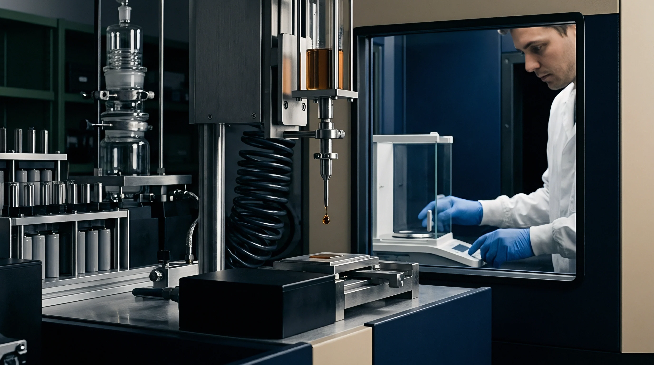
Adding active chemical agents to the organic carbonate solvent mixture provides a direct way to stabilize high-nickel cathode interfaces. These additives oxidize preferentially on the cathode surface before standard ethylene carbonate or ethyl methyl carbonate molecules can decompose.
This oxidative decomposition forms a coherent passivating layer that shields reactive tetravalent nickel from direct solvent exposure. Vinylene carbonate, fluoroethylene carbonate, and sulfur-bearing ring compounds like 1,3-propane sultone serve as sacrificial scavengers, their lower highest occupied molecular orbital energy levels ensuring that reactions begin at lower potentials than in the base solvent.
Exposed surface nickel ions reduce almost instantly during initial contact.
Unchecked electrolyte breakdown follows if no protective film forms.

Comparative Oxidation Potentials of Passivating Agents
Electrochemical measurements show that cyclic sulfates like ethylene sulfate oxidize around 4.25 volts versus lithium, forming lithium alkyl sulfate complexes on high-nickel particles. Fluorinated additives instead deposit inorganic lithium fluoride compounds that suppress surface oxygen evolution.
| Additive Name | Chemical Formula | Primary Reaction Mechanism | Oxidation Potential (V vs Li/Li+) | Primary Surface Film Product |
|---|---|---|---|---|
| Vinylene Carbonate | C3H2O3 | Radical polymerization forming poly-vinylene carbonate | 4.35 | Poly-carbonate network |
| Fluoroethylene Carbonate | C3H3FO3 | Dechlorination and fluorination yielding lithium fluoride | 4.45 | Lithium fluoride, poly-FEC |
| Ethylene Sulfate | C2H4O4S | Ring-opening reduction forming lithium alkyl sulfate | 4.25 | Lithium sulfate oligomers |
| Lithium Difluorobis(oxalate)phosphate | LiBC4O8F2 | Anionic oxidation forming fluorinated borates | 4.30 | LiF, boron-rich organics |
| Prop-1-ene-1,3-sultone | C3H4O3S | Electrophilic addition yielding sulfur-rich passivating film | 4.20 | Lithium sulfonate species |
An electrolyte with 1.5 weight percent ethylene sulfate cuts transition metal dissolution by 42 percent during 45 degree Celsius cycling at 4.25 volts.
Unpassivated high-nickel cathodes exhibit several structural failure mechanisms during high-voltage operation:
- Lattice oxygen release drives organic solvent oxidation, producing carbon dioxide gas and accelerating internal cell pressurization.
- Transition metal dissolution allows divalent nickel ions to migrate to the negative electrode, degrading the solid electrolyte interphase.
- Planar gliding fracture creates internal microcracks within secondary spherical particles, exposing fresh unpassivated crystal surfaces to the electrolyte.
- Surface phase transformation converts active rhombohedral structures into resistive rock-salt layers that increase charge transfer impedance.
Initial impedance spikes under high additive concentrations typically resolve after fifty full charge cycles during bench testing.


Interphase

Cathode Surface Passivation Layer Architecture
The chemical boundary on nickel-rich active materials forms an organic-inorganic dual layer between two and fifteen nanometers thick. Right next to the active oxide crystal, the inner region consists of dense inorganic compounds like lithium fluoride, lithium oxide, and lithium carbonate. The outer region, facing the liquid solution, contains polymeric alkyl carbonates and poly-ether oligomers.
Inorganic compounds supply high mechanical stiffness and low electronic conductivity, blocking continuous electrolyte oxidation. Organic oligomers provide elastic flexibility, preserving structural integrity through volume changes during lithium extraction and insertion.
Without a stable film, overall thermal stability degrades rapidly.
Severe impedance growth eventually stifles rate performance.

Worked Calculation of Interphase Layer Growth and Cell Resistance
To quantify how boundary film growth affects electrical performance, consider a 50 ampere-hour pouch cell using LiNi0.80Mn0.10Co0.10O2 material. Starting with a 3.0-nanometer film and an area-specific charge-transfer value of 15.0 ohm-centimeters squared, continuous high-voltage storage at 4.30 volts increases film thickness to 8.5 nanometers after five hundred hours at 45 degrees Celsius.
Across a total cathode active area of 2.4 square meters, the initial charge-transfer resistance is 0.000625 ohms. As the passivating boundary thickens to 8.5 nanometers, area-specific charge-transfer resistance expands proportionally to 42.5 ohm-centimeters squared, adding 1.15 milliohms to cell DC internal resistance. At a continuous discharge rate of 100 amperes, this growth generates an extra 11.5 watts of localized thermal dissipation, accelerating secondary decomposition reactions.
| Cathode Material | Additive Package | Film Thickness (nm) | Area-Specific Resistance (ohm-cm2) | Primary Inorganic Species |
|---|---|---|---|---|
| LiNi0.80Mn0.10Co0.10O2 | 2% VC + 1% DTD | 4.2 | 18.5 | Lithium fluoride, Li2CO3 |
| LiNi0.90Mn0.05Co0.05O2 | 2% FEC + 1.5% LiDFOB | 6.1 | 28.2 | Lithium fluoride, B2O3 derivatives |
| NCMA (Ni 89%) | 1.5% DTD + 0.5% PES | 3.8 | 16.2 | Lithium sulfate, Al2O3 complexes |
| LiNiO2 | 3% FEC + 2% DTD | 8.5 | 42.0 | Lithium fluoride, Li2O |
| Data synthesized from high-precision differential capacity and electrochemical impedance spectroscopy measurements under controlled 45 degree Celsius testing conditions. | ||||
Uniform inorganic lithium fluoride layers suppress transition metal migration much more effectively than thick organic polymer matrices.
Inadequate passivation film formation leads directly to transition metal leaching from the cathode, rapid poisoning of the anode solid electrolyte interphase, and severe capacity fade that ruins cell commercial value before two hundred cycles.


Gas

What Passivation Degradation Triggers Rapid Gassing under High SOC Storage?
Gas generation in high-nickel pouch cells stems directly from lattice oxygen reacting with alkyl carbonate solvents at high states of charge. Above ninety percent state of charge, unpassivated surface sites catalyze decarboxylation and decarbonylation. Carbon dioxide and carbon monoxide form the main reaction products, alongside trace fluorinated hydrocarbons from salt breakdown.
Additive consumption proceeds rapidly during extended high-voltage storage.
Internal pressure increases as gaseous products accumulate in the pouch.

Decoupling Gas Evolution from Interphase Oxidation
Differential electrochemical mass spectrometry isolates volatile products generated by lattice breakdown from those caused by solvent oxidation. Active additives like lithium difluorobis(oxalate)phosphate capture free radicals before solvent oxidation takes place, curbing internal pouch expansion.
Meeting UN 38.3 test T.2 thermal criteria requires pouch cells stored at 72 degrees Celsius to show less than two percent volumetric expansion from internal swelling.
Quality inspection for high-nickel cell orders demands systematic evaluation of volatile generation indicators:
- Volumetric swelling tolerance determines maximum permissible pouch expansion during elevated temperature storage tests.
- Gas composition profiling separates lattice oxygen release from electrolyte solvent oxidation using gas chromatography.
- Microcrack density audit quantifies secondary particle fracture rates after high-rate cycling under cold ambient conditions.
- Differential capacity retention tracks peak shifts associated with surface phase structural degradation over cycle life.
Where surface microcracking completely overwhelms additive film repair during high-C-rate fast charging remains an open question in high-nickel electrochemical modeling.


Assay

Electrochemical Characterization and Differential Capacity Metrics
Evaluating high-nickel cathode surface protection relies on non-destructive AC impedance spectroscopy and high-precision coulometry. Analyzing Nyquist spectra across state-of-charge ranges isolates charge-transfer arc expansion from bulk electrolyte resistance changes. A growing mid-frequency semicircle signals progressive surface phase transformation and the buildup of an insulating layer.
Consequently, usable cell capacity drops over time.
Concurrently, voltage decay accelerates continuous oxidation at particle boundaries.

Transport Safety Verification and Testing Boundaries
Dangerous goods regulations mandate physical and thermal abuse testing for high-nickel cells. Standards under UN 38.3, specifically tests T.1 through T.8, establish baseline mechanical and thermal limits. High-nickel cells with compromised surface passivation frequently suffer thermal runaway during the UN 38.3 T.2 thermal test, which holds fully charged units at 72 degrees Celsius for six hours.
| Test Standard | Specific Test Clause | Environmental Conditions | Pass Criteria | Primary Failure Mode |
|---|---|---|---|---|
| UN 38.3 | T.2 Thermal Test | 72 deg C for 6 hours, then -40 deg C for 6 hours | No mass loss, no disassembly, no fire | Internal swelling, thermal runaway |
| UN 38.3 | T.5 External Short Circuit | 55 deg C ambient, short circuit less than 0.1 ohm | External temp below 170 deg C, no fire | Separator melting, cathode collapse |
| IEC 62133-2 | Clause 7.3.2 Thermal Abuse | 130 deg C chamber ramp at 5 deg C per minute | No explosion or fire within 10 minutes | Exothermic cathode decomposition |
| UL 1642 | Clause 13 Projectile Test | Direct flame exposure until cell vents or explodes | No cell fragment penetrates wire screen | Uncontrolled gassing, structural rupture |
Differential capacity peaks above 4.1 volts track the onset of surface rock-salt transformation in high-nickel cathodes.
Incoming inspection and shipping validation for high-nickel cell shipments follows a strict four-step sequence:
- Verify that UN 38.3 test summaries match the exact bill of materials and factory site producing the shipped lot.
- Perform AC impedance screening on a three percent lot sample to confirm mid-frequency charge-transfer resistance falls within specified limits.
- Discharge incoming cell samples to a thirty percent state of charge to comply with IATA Packing Instruction 965 air carriage caps.
- Place representative cells under 60 degree Celsius storage for fourteen days to measure open-circuit voltage decay and pouch expansion.
Section IA of IATA Packing Instruction 965 caps state of charge at thirty percent for air shipment, requiring cell vendors to adjust quality inspection protocols before transit.

Warranty

Commercial Risk Allocation and Regulatory Compliance Dossiers
Procuring high-nickel lithium cells requires clear contract language governing cathode degradation limits and regulatory obligations. Under EU Battery Regulation 2023/1542, importers of record bear legal responsibility for performance metrics, carbon footprint declarations, and supply chain due diligence dossiers. Substandard surface passivation that leads to rapid capacity loss triggers statutory guarantee claims from buyers.
Unpassivated surfaces react aggressively under high-voltage storage conditions.
Strict shipping compliance rules govern all international cell movement.
Ultimately, landed costs reflect initial cell manufacturing quality.

Contractual Pass-Through of Field Degradation Liability
Supply agreements for battery modules regularly incorporate capacity retention clauses tied to additive specifications. Coupling capacity retention metrics to additive consumption signatures protects integrators from paying full landed costs on poorly passivated inventory.