Submicron Carbide Characterization Protocols for Battery Tooling
Characterizing submicron carbide through magnetic saturation, Palmqvist toughness, and SEM grain sizing eliminates edge burrs during battery foil slitting.

Grain
Sintered tungsten carbide tool blanks with average particle dimensions between 0.2 µm and 0.8 µm deliver the yield strength required for slitting thin current collector foils. High-speed continuous rotary slitting knives and pouch cell die punches endure extreme mechanical shear stress along their cutting bevels, a demand submicron grains handle without deforming. By contrast, standard tungsten carbide formulations with coarse grain distributions above 1.5 µm tend to suffer intergranular cracking under dynamic shear loads.
Refining particle size raises hard metal yield strength in line with the Hall-Petch relationship, boosting macro-hardness while keeping the tool edge resistant to local collapse.
Characterizing crystal size distribution demands high-resolution metallography. Because optical light microscopy lacks the spatial resolution to resolve submicron features, standard grain counting methods fail here. Quantitative sizing instead relies on Field Emission Scanning Electron Microscopy imaging paired with Electron Backscatter Diffraction crystal mapping.
ASTM E112 and ISO 4499-2 standards define intercept procedures for quantifying mean linear intercept length, log-normal distribution width, and maximum grain diameter thresholds. This level of microstructural homogeneity matters because it eliminates the localized stress points that trigger micro-chipping during high-volume battery foil conversion.

Electron Backscatter Diffraction Metallography
Quantifying structural crystallography at high spatial resolution isolates crystalline orientation and phase distribution across polished tool surfaces. Orientation mapping exposes local crystallographic texture, phase purity, and grain boundary character distribution. High-angle grain boundaries above fifteen degrees dominate ultrafine tungsten carbide networks, offering strong resistance to slip propagation under heavy compressive loading.
Automated indexing software then calculates the equivalent circle diameter across tens of thousands of individual carbide grains per sample region.
Abnormal grain growth creates localized structural vulnerabilities inside submicron matrices. When singular coarse grains exceed three times the mean particle diameter, they disrupt binder distribution and concentrate applied stresses. These isolated large crystals then act as crack nucleation sites during high-cycle shearing of copper and aluminum current collectors.
Strict quality control protocols therefore set clear upper limits on individual crystal size to prevent premature bevel fracture.
Mean grain diameter measurements exceeding 0.8 micrometers correlate with a 35 percent decrease in tool blade edge lifetime during continuous copper foil slitting.
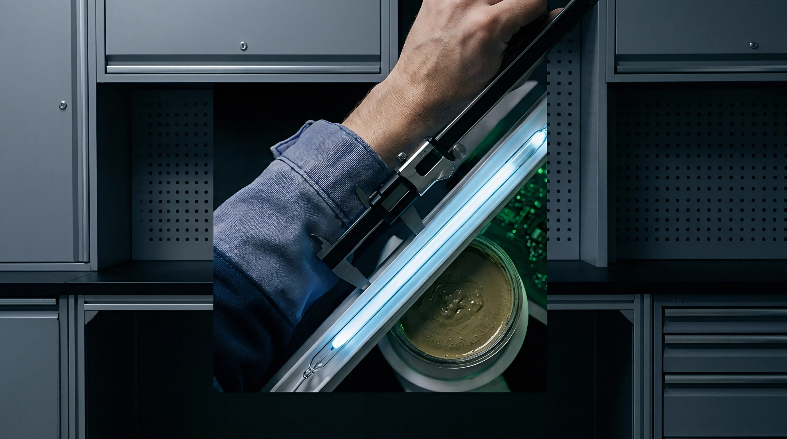
Field Emission Scanning Microscopy Calibration
Standard imaging protocols at magnification levels above 20,000x require sharp contrast between dense refractory metal carbides and the cobalt binder phase. Samples receive a mechanical lap finish down to 0.25 µm diamond slurry before chemical etching with Murakami reagent or hydrogen peroxide mixtures. Etching strips away surface metal matrices to bring tungsten carbide grain boundaries into view without rounding edge profiles.
Image processing algorithms use thresholding routines to separate carbide particles from surrounding binder networks. Calibrating against certified diffraction grating standards keeps dimensional measurements accurate across different imaging sessions. That matters because subtle discrepancies in threshold selection can artificially shift mean particle size metrics by up to eighteen percent.
Standardized threshold parameters eliminate this analytical bias when comparing raw material shipments from different powder refiners.
Submicron grain matrices directly govern edge sharpening tolerances. Fine microstructures allow grinding wheels to polish cutting bevels down to tip radii under 0.5 µm without pulling whole crystals out of the metallic matrix. Coarse structures, by contrast, suffer from grain pull-out during diamond grinding, leaving microscopic edge notches that produce burrs on electrode foils.
Maintaining clean edge geometry extends tool life and preserves precise shearing clearances.
The decision matrix for incoming tungsten carbide metallography establishes objective baseline standards for material qualification.
- Specimen Preparation Lap Finish Polishing sample surfaces down to a 0.05 µm colloidal silica finish eliminates sub-surface grinding damage that corrupts crystal diffraction indexing.
- Etching Contrast Control Applying Murakami etching solution for precisely twelve seconds reveals phase boundaries without pitting the metallic binder network.
- Magnification Calibration Baseline Verifying magnification scaling against certified pitch standards prior to data collection prevents dimensional calculation drift.
- Data Sampling Population Measuring a minimum of five thousand distinct grains across ten random fields of view ensures statistical representation of distribution skewness.
Material specifications for submicron tool blanks establish operational limits across battery conversion processes, where mechanical properties determine tool survival under high-frequency impact loading.
| Grade Class | Mean Grain Size (µm) | Binder Fraction wt% | Hardness (HV30) | Palmqvist Toughness (MPa m^0.5) | Application |
|---|---|---|---|---|---|
| 0.1 to 0.3 | 6.0 to 8.0 | 1950 to 2150 | 8.5 to 9.5 | Ultra-thin foil slitting blades | |
| 0.3 to 0.5 | 8.0 to 10.0 | 1750 to 1950 | 9.5 to 11.0 | Pouch cell die punches | |
| 0.5 to 0.8 | 10.0 to 12.0 | 1550 to 1750 | 11.0 to 13.0 | Heavy separator shearing knives | |
| 0.8 to 1.3 | 12.0 to 15.0 | 1350 to 1550 | 13.0 to 15.5 | Extrusion guide components |
Inadequate carbide characterization lets coarse inclusions pass into blade grinding, leading to sudden brittle fractures that shatter punch sets and halt high-speed cell production lines.


Binder
Cobalt and nickel matrices anchor refractory tungsten carbide grains within the consolidated tool body. This binder phase supplies plastic deformation capacity, absorbing kinetic impact energy during repetitive punching cycles. Pure cobalt remains standard for dry foil shearing because of its excellent wetting behavior and strong mechanical adhesion to carbide facets.
However, wet slurry environments in slot-die coating and calendar roll scaper blades present aggressive chemical conditions that rapidly degrade pure cobalt matrices.
Slurry formulations containing organic solvents, dissolved salts, and active cathode materials trigger leaching corrosion inside tool binder networks. As leaching dissolves the supporting matrix around surface carbide crystals, the unsupported grains dislodge under abrasive friction, accelerating edge recess and rounding. Replacing pure cobalt with nickel-chromium or cobalt-nickel-chromium alloy matrices improves corrosion resistance by forming a protective passive oxide film over exposed binder pools.

Chemical Passivation in Slurry Tooling
Exposure to aqueous cathode formulations and acidic organic solvents attacks metallic binder phases through localized galvanic corrosion. Adding between 0.5 and 1.5 weight percent chromium forms stable chromium oxide films within the binder matrix. This passive layer impedes electron transfer between refractory carbide phases and the metallic binder, suppressing electrochemical dissolution.
In acidic N-Methyl-2-pyrrolidone solvent recovery streams, binder leaching accelerates whenever chromium levels drop below critical passivation thresholds.
Corrosion testing evaluates weight loss and dimensional degradation following immersion in standardized slurry environments. Electrochemical impedance spectroscopy tracks polarization resistance over extended exposure times. When operating effectively, a robust passive film keeps binder dissolution rates below 0.01 milligrams per square centimeter per hour, preserving cutting geometry during continuous wet slurry processing.
According to ISO 3326 guidelines, coercive force values below 28 kiloamperes per meter indicate excessive grain growth and binder pool formation in ultrafine tool formulations.
Magnetic Saturation and Coercivity Measurements
Ferromagnetic phase content determines the proportion of unreacted metallic element remaining after thermal consolidation. Magnetic saturation measurements quantify total active cobalt or nickel content inside the sintered hard metal body. During vacuum sintering, variations in carbon content alter binder stoichiometry.
A carbon deficiency forces tungsten to dissolve into the cobalt matrix ~ forming brittle eta-phase complex carbides that reduce impact toughness ~ while excess carbon causes free carbon precipitation that weakens binder cohesive strength.
Coercive force testing measures magnetic domain wall mobility, serving as a non-destructive proxy for grain size and binder mean free path distribution. Higher coercivity values point to finer grain structures and narrower binder channels between adjacent carbide crystals. Using magnetic characterization in this way verifies heat treatment consistency across production batches without destroying costly finished tools.
Because cobalt binder leaches in water, systematic characterization tracks chemical and physical binder transformations across production stages.
- Magnetic Saturation Screening Measuring magnetic moment per unit mass establishes binder stoichiometry and detects harmful eta-phase formation prior to precision grinding.
- Coercivity Field Measurement Evaluating magnetic domain wall resistance confirms mean free path dimensions between carbide grains without sectioning finished blades.
- Chemical Leach Exposure Test Submerging material samples in target battery slurry media for seventy-two hours quantifies binder dissolution rates and mass loss.
- Inductively Coupled Plasma Analysis Spectrometric inspection of post-exposure solution streams measures exact concentration of leached cobalt, nickel, and chromium ions.
Edge degradation often stems from excessive carbon deficiency within sintered binder formulations rather than aggressive solvent pH levels.

Edge
Shearing current collectors demands a sharp blade profile capable of enduring millions of cyclic mechanical impacts without micro-level degradation. As an edge rounds, burr height increases along copper and aluminum electrode margins. If burrs grow too high, they puncture thin polyolefin separators during cell winding or stacking, causing internal short circuits and cell failure.
Preserving edge sharpness therefore comes down to balancing microhardness against fracture toughness within the hard metal formulation.
Micro-chipping represents the primary failure mode for high-hardness submicron tools. Minute fractures along the cutting bevel ruin edge definition and scatter conductive metallic debris inside cleanroom converting spaces. Restricting the binder mean free path to submicron dimensions stops cracks from propagating along cobalt channels, improving local fracture resistance without sacrificing macro-hardness metrics.
Fracture Toughness Vs Microhardness
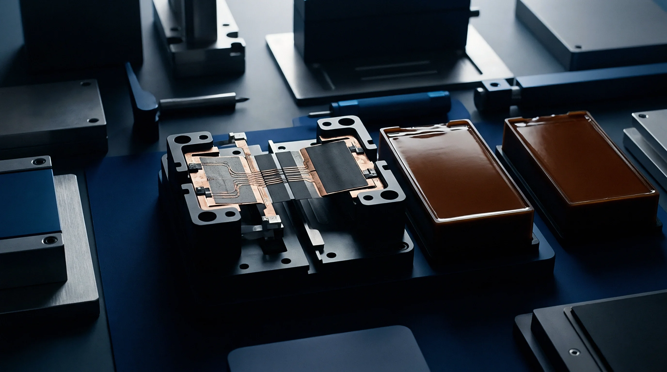
Indentation loading per ASTM E384 establishes mechanical hardness, while crack tip extension lengths under a Vickers impression define resistance to catastrophic cleavage. Palmqvist fracture toughness testing calculates resistance to crack growth using short surface cracks generated by Vickers indentations under heavy 30 kilogram loads. Submicron carbide grades achieve high Vickers hardness numbers exceeding 1800 HV30 while retaining Palmqvist toughness values above 10 MPa m^0.5.
As binder volume increases, hardness drops. Higher binder volume fractions boost toughness, but they also accelerate abrasive wear along tool flanks. Optimizing tool life requires matching hard metal compositions to specific foil thicknesses and tensile strengths.
Harder copper alloys and ceramic-coated separator materials require higher toughness grades to absorb dynamic shock without chipping along the edge.
Because shear stress causes edge chipping, mechanical properties across submicron hard metal classes directly dictate blade performance.
| Grain Classification | Vickers Hardness (HV30) | Palmqvist Toughness (MPa m^0.5) | Compressive Strength (GPa) | Transverse Rupture Strength (MPa) |
|---|---|---|---|---|
| 2050 | 8.8 | 7.2 | 3400 | |
| 1880 | 10.2 | 6.8 | 3800 | |
| 1680 | 11.8 | 6.1 | 4100 | |
| 1480 | 13.5 | 5.4 | 4500 |

When Does Micro-Chipping Mandate Complete Blade Replacement?
Pitting depth exceeding five micrometers creates burrs on aluminum foils that compromise separator insulation safety. Continuous inline optical inspection monitors edge integrity during high-speed slitting. When individual chipping notches exceed allowable depth limits, operators pull the blade assembly for precision diamond re-grinding.
Edge micro-chipping alters local stress distribution during shearing operations. Microscopic notches act as stress concentrators, promoting rapid crack propagation across the cutting bevel. Regular maintenance schedules prevent these small edge defects from evolving into deep structural cracks that render tools unrepairable.
Understanding tool failure modes helps engineers optimize maintenance intervals and refine blade geometry.
- Abrasive Flank Wear Friction from ceramic slurry coatings gradually wears away flank surfaces, increasing edge radius and cutting force requirements.
- Micro-Chipping Notch Formation Dynamic shock loads dislodge small clusters of carbide grains along the cutting bevel, leaving jagged edge profiles.
- Thermal Crack Spalling Cyclic friction heat generates intense localized thermal gradients, producing parallel cracks perpendicular to the cutting edge.
- Binder Extrusion Shear Deformation Heavy compressive forces squeeze soft metallic binder out of the surface layer, causing carbide grain collapse.
The precise threshold where microscopic elastic deformation transitions into irreversible micro-cleavage under ultra-high-speed foil shearing remains an open topic in physical modeling.


Flaw
Internal voids and non-metallic inclusions weaken structural integrity under concentrated compressive forces. Sintering micro-porosity creates pre-existing sites where cracks initiate under fatigue loading. ISO 4499 specifies porosity classification scales from A02 through A08 based on pore diameter and frequency per unit area.
Achieving pore-free microstructures requires advanced consolidation techniques such as Sinter-HIP processing, which combines vacuum sintering with high-pressure argon gas.
Inclusions from raw tungsten powder contamination or furnace lining degradation cause severe structural weaknesses. Iron, silicon, and titanium impurities alter local thermal expansion coefficients, creating residual internal stress fields after cooling. Non-destructive evaluation methods inspect blank interiors before committing to expensive precision machining.

Hot Isostatic Pressing Density Checks
Post-sintering thermal cycles at gas pressures reaching 150 megapascals eliminate micro-porosity within consolidated preforms. Argon gas pressure collapses internal pockets and welds pore boundaries at elevated sintering temperatures. Sinter-HIP treatment raises density to within 99.99 percent of theoretical limits, removing structural defects that compromise impact resistance.
Density evaluation via Archimedes immersion testing offers rapid verification of the consolidated state. Precision analytical balances measure mass changes in air and distilled water to detect subtle density variations caused by residual porosity or phase imbalances. Discrepancies exceeding 0.02 grams per cubic centimeter signal inadequate hot pressing or composition control failures.
Carbide blanks failing ISO 4499 porosity rating A02 exhibit localized stress concentrations that shorten fatigue life under high-frequency stamping.

Ultrasonic Screening and Micro-CT Scans
Acoustic signal attenuation across high-frequency transducers reveals buried density variations down to fifteen micrometers. Ultrasonic testing submerges tool blanks in liquid coupling media while scanning high-frequency acoustic waves across cross-sections. Internal flaws reflect acoustic energy, mapping defect location and magnitude without damaging test specimens.
Industrial Micro-Computed Tomography provides three-dimensional volumetric inspection of critical tool components. X-ray absorption contrast isolates internal voids, uncombined carbon inclusions, and high-density metallic impurities. Generating these defect maps lets engineers reject flawed raw blanks before spending machine hours on expensive diamond grinding.
Because defects concentrate local mechanical stress, non-destructive eddy current testing screens sintered die blanks using structured inspection steps.
- Demagnetize the sintered carbide blank to remove residual magnetic fields that distort electromagnetic measurement sensors.
- Mount the blank in a precision rotary holding fixture to ensure constant probe positioning relative to test surfaces.
- Calibrate high-frequency eddy current probes against reference hard metal standards containing EDM notch flaws of known depth.
- Scan probe sensors along primary stress axes at fixed five-millimeter spacing to map near-surface conductivity variations.
- Log signal anomalies exceeding twenty percent baseline noise threshold for secondary ultrasonic verification.
Standard procurement agreements following ISO 4499 Class B limits mandate lot rejection whenever uncombined carbon inclusions exceed ten micrometers in cross-sectional dimension.


Ledger
Tooling economics balance initial non-recurring engineering expenses against the total linear meters of battery foil cut before blade failure. Submicron tungsten carbide tools carry higher upfront material and processing costs compared to standard micrograin grades. However, their density and hardness extend sharpening intervals by up to three hundred percent, lowering the total cost per converted battery pack.
Because re-grind limits depend on flaw depth, calculating lifetime cost requires analyzing initial blank costs, sharpening frequencies, downtime expenses, and yield loss from edge-defect burrs.
Precision re-grinding restores cutting bevel geometry by removing worn material layers with specialized diamond wheels. Tool blanks must provide sufficient cross-sectional stock to survive multiple re-grind operations over their operational lifespan. Managing tool inventory ledgers ensures spent blades undergo re-grinding before micro-chipping damage extends past economic restoration limits.

Amortization and Re-Grind Budgets
Calculating total cost per battery cell produced requires accounting for precision re-grinding expenses, shipping logistics, and spare tooling inventory holding costs. A single high-speed slitting unit uses paired upper and lower carbide rotary blades operating under controlled axial preload forces. Excessive mechanical runout or uneven clamping pressure accelerates local wear, dropping achievable re-grind cycles from ten down to four.
In a high-volume manufacturing plant running double-shift converting operations on double-sided cathode foils, standard tool steel blades require sharpening every fifty thousand linear meters, causing substantial downtime and labor costs. Submicron carbide blades run for two hundred fifty thousand linear meters between re-grind cycles. These lower maintenance frequencies offset higher initial blank expenses within six months of continuous production.
Because dense carbide resists abrasive slurry, the financial comparison between tool steel and submicron carbide tooling sets highlights operational balance factors.
| Parameter Metric | Standard Tool Steel | Submicron Carbide (WC-Co) | Ultrafine Carbide (WC-Ni-Cr) |
|---|---|---|---|
| $1,200 | $4,500 | $5,800 | |
| 50,000 m | 250,000 m | 350,000 m | |
| 15 cycles | 8 cycles | 10 cycles | |
| $150 | $450 | $500 | |
| 800,000 m | 2,250,000 m | 3,850,000 m | |
| $431 | $360 | $280 |
First Article Quality Acceptance Criteria
Procurement documents specify acceptable dimensional tolerances, surface roughness limits, and grain distribution metrics prior to commercial release. Certified inspection reports must accompany incoming carbide tool shipments, verifying compliance with mechanical and metallurgical requirements. Non-destructive eddy current screening and density measurements validate structural integrity before components enter active production streams.
Because tool steel deflects under load, quality agreements specify lot acceptance sampling rules based on ANSI/ASQ Z1.4 standards. Non-conforming lots showing excessive porosity or improper binder content trigger immediate supplier return procedures. Matching submicron carbide grain characterization directly to incoming blank inspection paperwork guarantees predictable tool life across volume manufacturing operations.