Quantifying Carbide Banding Severity in Tool Steels for Cell Stamping Dies
Quantifying tool steel carbide banding via ASTM E1268 stereology prevents micro-chipping and premature fracture in high-takt battery cell stamping dies.


Anisotropy
Deep drawing aluminum prismatic enclosures and nickel-plated steel cell cans at high speeds puts severe cyclic shear stress on die cutting edges. When stamping cell cases at production rates over 180 strokes per minute, microstructural uniformity in the tool steel determines whether die inserts last ten million cycles or break around cycle three hundred thousand. Primary eutectic carbides in conventionally cast tool steels like AISI D2 and M2 do not freeze uniformly during ingot solidification.
Heavy forging and rolling operations then flatten and stretch these brittle carbide networks along the primary working direction, creating parallel lanes of concentrated primary carbide clusters next to carbide-depleted matrix steel. This directional structural alignment establishes anisotropic mechanical behavior that directly threatens die life on battery cell manufacturing lines.
Banded tool steel handles loads differently along the rolling direction versus across it. Tensile strength might look adequate along the bands, but across them, fracture toughness drops precipitously. When press tools encounter shock loads during blanking of 3004-H14 aluminum strip or deep drawing of nickel-plated diffusion-annealed steel, micro-cracks form along lines of primary carbide banding.
Tensile stresses acting perpendicular to the aligned carbide bands cleave the brittle primary M7C3 or M6C carbide particles or pull them away from the tempered martensite matrix. Dies manufactured without accounting for grain and band orientation suffer premature catastrophic splitting, micro-chipping along punch radii, and uneven elastic deflection across the tool clearance gap.
Mechanical Degradation across Directional Segregation Paths
Dynamic impact forces during high-takt cell envelope blanking exploit structural weaknesses within segregated microstructures. In conventional ingot-cast tool steel, primary carbides form coarse, continuous networks that flatten into dense bands during billet reduction. Microhardness measurements across these microstructural bands show sharp hardness gradients over spatial distances under twenty micrometers.
The tempered martensitic matrix typically shows microhardness values between 600 HV0.1 and 650 HV0.1, whereas adjacent carbide-rich bands reach microhardness levels between 850 HV0.1 and 1100 HV0.1. This severe microhardness delta produces localized stress concentrations under external loads.
Under repeated press impacts, elastic strain mismatches develop between high-modulus carbide clusters and the lower-modulus matrix. The matrix deforms elastically while rigid primary carbides resist, generating severe shear strain at phase boundaries. Shear strain induces subsurface micro-void formation and interface decohesion.
In cell case stamping dies operating with punch-to-die clearances held between four percent and eight percent of sheet thickness, micro-voids coalesce into macro-cracks that propagate along segregation lanes. Flakes of tool material detach from the working edge, altering punch geometry and throwing burrs on stamped cell cans that exceed specified drawing tolerances.
Transverse impact toughness drops by 48 percent when primary carbide band spacing contracts below 15 micrometers under ASTM E23 unnotched Charpy testing at 22 degrees Celsius.
Directional variance also compromises thermal processing during die fabrication. During vacuum heat treatment and quenching, volumetric expansion from the martensitic phase transformation happens unevenly across microstructural bands. The carbide-depleted matrix bands transform at higher temperatures and expand to a different degree than high-carbon, high-alloy carbide-rich regions.
This differential expansion introduces permanent dimensional anisotropy into finished die inserts. Punches ground to precise cylindrical geometries warp into subtle elliptical profiles post-quenching, destroying uniform die clearance and accelerating localized friction during cell container draw cycles.
Primary Carbide Segregation Mechanics in Cold-Work Tool Steels
Solidification kinetics in large commercial ingots drive the initial segregation of alloy elements. During the cooling of high-carbon, high-chromium tool steels, iron-rich dendrites freeze first, rejecting carbon, chromium, vanadium, and molybdenum into the remaining liquid between dendritic arms. This enriched liquid freezes last as a eutectic mixture of alloy matrix and coarse primary carbides.
In AISI D2, these primary carbides consist predominantly of chromium-rich M7C3 types, which possess extreme hardness but negligible ductility. In high-speed steels such as AISI M2, tungsten and molybdenum form brittle M6C carbides alongside hard vanadium-rich MC carbides.
Subsequent hot reduction by forging or rolling breaks apart the coarse interdendritic eutectic network but fails to dissolve primary carbides. Heavy plastic working elongates the broken carbide clusters into continuous parallel streams aligned with the mill rolling direction. The severity of this microstructural alignment correlates directly with ingot size and reduction ratio.
Larger ingots cool slower, producing coarser eutectic structures and wider segregation bands in the final bar stock. When toolmakers wire-EDM die punches directly from centerline sections of large-diameter rolled bars, primary carbide bands run parallel or perpendicular to the primary cutting edge, creating defined failure planes along the tool face.
Evaluating tool steel bars from various melt sources verifies directional toughness ratios before allocating stock to die component production. Transverse unnotched Charpy impact values in heavily banded ingot-cast D2 frequently measure less than twelve Joules, whereas longitudinal specimens from the same bar reach twenty-five Joules. This two-to-one property asymmetry demonstrates why unquantified carbide segregation presents an unmanageable risk in high-volume cell stamping tools.
When a blanking punch encounters asymmetrical material resistance from high-strength cell envelope strip, the side with lower transverse fracture toughness yields first, resulting in edge flaking and premature die replacement.
- Localized Edge Chipping occurs when high impact stresses cleave primary carbide bands terminating directly at the cutting radius, creating notch sites that accelerate macro-fracture.
- Dimensional Distortion Drift manifests during quenching when unequal phase expansion across segregated bands warps precision punch profiles beyond acceptable geometric tolerances.
- Asymmetric Friction Coefficients develop along die cavity walls as hard carbide lanes wear unevenly against soft aluminum sheet, causing localized galling and score marks on drawn cell cases.
- Fatigue Micro-crack Propagation follows continuous longitudinal carbide bands under cyclical compression, shortening total die life from millions of strokes to several hundred thousand.
Failure to specify and verify carbide distribution limits in raw tool steel stock guarantees premature die destruction on high-speed cell manufacturing lines, shifting unaccounted replacement NRE costs and unplanned press line downtime directly onto the cell component supplier.


Etch
Quantifying carbide alignment requires precise metallographic sample preparation followed by disciplined chemical processing to expose phase boundaries. Raw optical inspection of polished steel surfaces fails to distinguish between primary alloy carbides, secondary precipitation carbides, and the surrounding martensitic structure. Chemical contrast methods dissolve or discolor specific phases selectively, allowing optical and digital imaging systems to map carbide distribution networks.
Metallographers cut samples along both longitudinal and transverse axes relative to the bar rolling direction, mounting them in conductive resin to protect delicate edge geometries during mechanical grinding and polishing steps.
Standard chemical etchants reveal different microstructural features depending on acid concentration and exposure duration. A four percent Nital solution etches the tempered martensite matrix, exposing outlines of large primary carbides while leaving the carbides unattacked and bright. Etching with Vilella’s reagent enhances contrast between chromium carbides and the matrix, which is necessary for automated image analysis on AISI D2 and D3 steels.
For high-speed steels containing tungsten and molybdenum, tint etching using Beraha’s reagent or heat-tinting techniques colors the matrix while highlighting MC and M6C carbides in distinct hues. Accurate quantitative stereology depends entirely on achieving crisp, repeatable contrast without over-etching, which creates artificial halos around carbides and skews digital area fraction measurements.
Quantitative Stereology and ASTM E1268 Parameter Derivation
Objective classification of microstructural alignment relies on ASTM E1268, the standard practice for assessing the degree of banding or orientation of microstructures. Quantitative evaluation replaces subjective visual chart comparisons with mathematical stereological parameters derived from directional line-intercept counts. Metallographers lay a grid of test lines parallel and perpendicular to the deformation axis across digital microstructural images acquired at magnifications between 100x and 500x.
Counting the number of feature boundary intersections along both grid orientations yields fundamental stereological metrics that define spatial distribution.
The primary parameters calculated under ASTM E1268 include the mean mean-free-path between bands, the anisotropy index, and the degree of banding. Intercept density per unit length perpendicular to the deformation direction, denoted as N-perpendicular, is compared against intercept density parallel to the deformation direction, denoted as N-parallel. The Anisotropy Index, AI, represents the ratio of N-perpendicular to N-parallel.
A completely isotropic microstructure with randomly distributed spherical carbides yields an AI of 1.0. As carbide banding increases in severity, N-perpendicular rises relative to N-parallel, pushing the AI value to 2.0, 3.0, or higher. Microstructures exhibiting an AI above 1.8 contain severe continuous banding that severely degrades transverse mechanical properties.
The stereological Degree of Banding, expressed as Omega, provides a normalized scalar metric ranging from zero to one. Calculate Omega using the formula:
Omega = (N-perpendicular – N-parallel) / (N-perpendicular + 0.571 N-parallel)
A calculated Omega value of 0.0 indicates a non-oriented, homogeneous microstructure, while an Omega approaching 1.0 reflects extreme linear orientation where carbides align in continuous, unbroken parallel bands. In precision cell stamping die specifications, setting maximum allowable thresholds for both AI and Omega ensures that raw material suppliers deliver tool steel capable of withstanding multidirectional stamping forces.
Image analysis software automates intercept counting across multiple fields of view to ensure statistical validity. Analysts evaluate at least twenty random fields per sample section, aggregating data to calculate mean band spacing and carbide volume fraction. Microhardness profiling across identified bands complements stereological image metrics.
A series of micro-Vickers indentations made at 0.1 kilogram-force (HV0.1) across suspected band structures quantifies hardness variance. If microhardness values fluctuate by more than 150 HV0.1 between adjacent ten-micrometer measurement points, the material contains severe alloy segregation that will induce localized stress concentrations during stamping operations.
Metallographic Preparation Protocol for High-Contrast Banding Extraction
Achieving reproducible quantitative metallography requires strict adherence to multi-step specimen preparation protocols. Microstructural artifacts such as edge rounding, scratch deformation, and carbide pull-out corrupt digital image segmentation, leading to false stereological measurements. The preparation sequence must maintain flat surface planarity while preserving hard primary carbides embedded in the softer matrix.
- Section specimen coupons from raw bar stock using a slow-speed diamond wafering saw under continuous liquid coolant flow to prevent localized thermal tempering.
- Mount sectioned coupons in thermal-setting epoxy resin containing mineral fillers to ensure superior edge retention during planar grinding.
- Perform coarse grinding on silicon carbide papers from 240-grit to 1200-grit using water lubricant at low platen rotational speeds.
- Polishing proceeds on synthetic silk cloths using diamond suspensions of six, three, and one micrometer particle sizes sequentially with glycol-based lubricant.
- Final chemical-mechanical polishing uses 0.05-micrometer colloidal silica suspension on a medium-nap cloth for ninety seconds to remove sub-surface deformation.
- Immerse the polished specimen in freshly prepared Vilella’s reagent for fifteen seconds, rinse immediately with isopropyl alcohol, and dry under hot air.
- Calibrate digital optical microscope camera magnification against a certified stage micrometer prior to capturing image fields for automated intercept counting.
Comparing raw ingot-cast tool steels against refined electroslag remelted (ESR) and powder metallurgy (PM) grades using this quantitative protocol highlights substantial performance gaps. In conventional ingot-cast D2, measured Anisotropy Index values consistently range between 2.1 and 2.8, with degree of banding values exceeding 0.45. In contrast, PM tool steels like CPM 10V or Vanadis 4 Extra yield Anisotropy Index values between 1.02 and 1.08, confirming an isotropic carbide distribution.
The absence of linear carbide orientation in PM steels eliminates directionality in mechanical performance, allowing die designers to orient punch and die components without regard to raw material bar rolling axes.
| Tool Steel Grade | Melting / Processing Route | Anisotropy Index (AI) | Degree of Banding (Omega) | Mean Band Spacing (µm) | Microhardness Delta (HV0.1) |
|---|---|---|---|---|---|
| AISI D2 | Conventional Ingot Cast | 2.45 | 0.52 | 12.4 | 210 |
| AISI D2 | Electroslag Remelted (ESR) | 1.55 | 0.28 | 28.6 | 110 |
| AISI M2 | Conventional Ingot Cast | 2.18 | 0.44 | 14.1 | 185 |
| AISI M2 | Electroslag Remelted (ESR) | 1.42 | 0.22 | 31.2 | 95 |
| CPM 10V | Powder Metallurgy (PM) | 1.04 | 0.03 | None (Homogeneous) | 25 |
| Vanadis 4 Extra | Powder Metallurgy (PM) | 1.03 | 0.02 | None (Homogeneous) | 20 |
| Bohler K390 | Powder Metallurgy (PM) | 1.05 | 0.04 | None (Homogeneous) | 30 |
| Data represents mean values obtained across 30 random fields per sample section inspected under ASTM E1268 parameters. Etchant: Vilella’s reagent for D2/PM grades, 4% Nital/Beraha’s tint for M2. Microhardness delta measures peak-to-valley variance across adjacent 10-micrometer test steps. | |||||
Compliance with ASTM E1268 degree of banding scale level 4 or higher invalidates the tool steel supplier microstructural warranty on punch tips subjected to high-speed blanking.
Specialty steel distributors frequently push back when tooling engineers reject material stock based on quantitative stereological data, citing standard mill chemical certs and macro-etch ratings as sufficient commercial quality norms under the view that micro-structural carbide banding falls within acceptable manufacturing variation. This argument ignores the reality of high-takt cell stamping tooling, where localized microstructural defects directly induce multi-thousand-dollar press stoppages.


Wear
Stamping dies for battery component production experience aggressive mechanical degradation modes when carbide distribution lacks uniformity. In high-speed draw-and-ironing (D&I) presses forming aluminum 3004 prismatic cases or nickel-plated steel cylindrical cans, punch and die surfaces sustain millions of contact cycles under high localized contact pressures. When tool steel inserts contain linear carbide bands, surface topography degrades unevenly.
Soft matrix bands wear away rapidly through micro-abrasion, leaving raised ridges of brittle primary carbides exposed to direct contact with incoming sheet stock.
Exposed carbide bands experience extreme shear stresses as sheet metal slides across the die face. Lacking mechanical support from the surrounding, worn matrix, primary carbides fracture, producing micro-chips that break free and become trapped in the die cavity. These loose carbide particles act as loose abrasive media, causing severe three-body abrasive scoring along both the tool surface and the stamped battery cans.
In severe cases, high localized frictional heating causes metal transfer from the aluminum or nickel strip onto the tool steel matrix, initiating galling. Micro-galling alters punch dimensions, increases press load requirements, and generates tears in thin-walled cell enclosures.

Are Centerline Segregation Bands Primary Drivers of Punch Fracture?
Centerline segregation represents the most severe manifestation of microstructural banding, concentrating coarse primary eutectic carbides along the central core of rolled tool steel bars. When toolmakers machine slender blanking punches or high-aspect ratio wall-ironing punches from bar centers, these continuous carbide networks run directly down the longitudinal core of the tool. Under vertical impact loads, compressive stress waves travel through the punch body, generating internal shear stresses along the core interface.
The presence of continuous primary carbide lanes along the tool core establishes a preferential path for internal fatigue crack propagation. Tensile stress reflections originating at the punch tip interact with hard, brittle carbides in the centerline band. Micro-cracks initiate at brittle carbide cleavage sites and propagate rapidly along the longitudinal segregation path.
Punch fracture occurs without warning, often splitting the punch cleanly down its center axis. Stamping lines running at 200 strokes per minute cannot halt before damaged punch fragments strike adjacent die stations, causing catastrophic multi-station tool destruction.
Quantifying centerline segregation requires non-destructive ultrasonic testing combined with destructive cross-sectional microstructural analysis. Standard ultrasonic inspections detect macro-voids and massive inclusions but often fail to resolve micro-structural carbide bands. Tooling engineers specify deep-acid etching on bar cut-off samples using fifty percent hydrochloric acid at 70 degrees Celsius.
Severe centerline segregation exposes itself as a dark, porous central core on macro-etched discs, signalling stock that must be rejected before investing expensive CNC machining, wire-EDM, and heat treatment labor.

Die Clearance Drift and Edge Burr Mechanics
Maintaining tight, uniform clearance between punch and die cutting edges dictates burr height on stamped battery cell components. For precision cell envelope blanking, die clearance is typically set to six percent of the nominal sheet thickness, which corresponds to clearances as small as twelve micrometers when processing 0.20-millimeter nickel-plated steel strip. Non-uniform wear caused by carbide banding disrupts this delicate mechanical clearance.
As carbide-depleted matrix regions wear away faster along the cutting edge, the effective clearance gap widens selectively in areas corresponding to soft matrix bands. This localized clearance drift creates asymmetric cutting mechanics. Instead of shearing cleanly through the sheet metal, the punch pushes sheet material into the enlarged clearance gap, stretching the metal prior to fracture.
Excessive stretching generates heavy material burrs along the cut edge of the cell blank.
In lithium-ion battery packaging, burrs on drawn cases or cover plates present severe safety risks. Sharp metal burrs can puncture thin polyolefin separators during cell assembly or generate conductive metal fragments inside the cell container, leading to internal short circuits and thermal runaway events. When die clearance drifts due to microstructural tool wear, press operators must stop production to regrind punch and die edges, drastically reducing overall equipment effectiveness (OEE).
Uniform powder metallurgy tool steels eliminate localized wear drift, maintaining constant die clearance across extended production runs.
Excessive carbide band spacing accelerates localized die clearance expansion, forcing press operators to pull tools for regrinding long before reaching target production stroke counts.
A reliable rule of thumb for press shop engineers: when cutting-edge burr height on stamped aluminum cell cases increases by more than twenty percent over a fifty-thousand-stroke run, investigate punch face carbide segregation before attempting to modify press stroke alignment or lubricant delivery settings.


Specification
Eliminating carbide banding issues in cell stamping tooling requires stringent material selection criteria integrated directly into engineering drawings and purchase orders. Conventional ingot-cast tool steels such as AISI D2, D3, and M2 remain popular due to low raw material costs, but their structural limitations make them unsuitable for high-takt, high-precision battery manufacturing dies. Specifying advanced melt refining techniques or powder metallurgy grades eliminates harmful macro-segregation and ensures isotropic mechanical properties.
Electroslag remelting (ESR) improves microstructural cleanliness compared to conventional ingot casting. During ESR processing, a consumable electrode of the target alloy melts through a molten reactive slag pool under controlled conditions. Droplets of molten metal pass through the slag, which removes oxide and sulfide inclusions while promoting rapid, uniform solidification in a water-cooled copper mold.
The resulting ESR ingot features significantly finer eutectic carbide structures and reduced macro-segregation. While ESR steels still exhibit mild banding compared to powder metallurgy grades, their Anisotropy Index values fall within acceptable limits for medium-duty stamping applications.
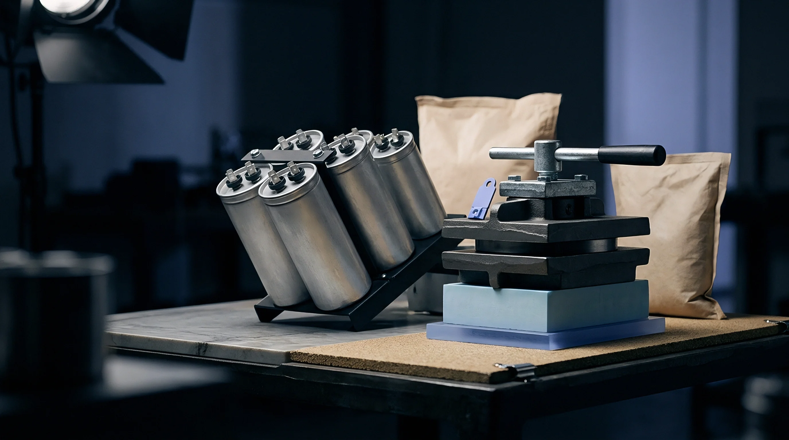
Powder Metallurgy versus Electroslag Remelting Performance Trajectories
Powder metallurgy (PM) technology provides the definitive solution to carbide segregation in high-performance tool steels. The PM manufacturing process bypasses slow ingot solidification entirely. Molten alloy streams flow through high-pressure nitrogen gas nozzles, atomizing the liquid metal into ultra-fine spherical droplets that freeze instantaneously at cooling rates exceeding 10,000 degrees Celsius per second.
This rapid cooling prevents alloy elements from segregating, forcing primary carbides to precipitate as microscopic, uniformly dispersed particles less than two micrometers in diameter.
Atomized alloy powder is collected, sealed in evacuated steel canisters, and consolidated under extreme heat and pressure using Hot Isostatic Pressing (HIP). The fully dense PM tool steel billet exhibits complete microstructural isotropy. Grades such as CPM 10V, Uddeholm Vanadis 4 Extra, and Bohler K390 combine extremely high volume fractions of vanadium-rich MC carbides with extraordinary fracture toughness.
Because these microscopic carbides distribute homogeneously throughout the tempered martensite matrix, PM tool steels display an Anisotropy Index close to 1.0, eliminating directional mechanical weakness and providing predictable wear resistance across all cutting surfaces.
Selecting between ESR and PM grades involves balancing raw material cost against required tool life and punch geometry. Slender punches, intricate die inserts, and high-speed draw rings subject to multi-axial stresses justify the cost premium of PM tool steels. Lower-stress stripper plates and heavy die shoe bases perform adequately when fabricated from ESR tool steels or high-toughness alloy grades.
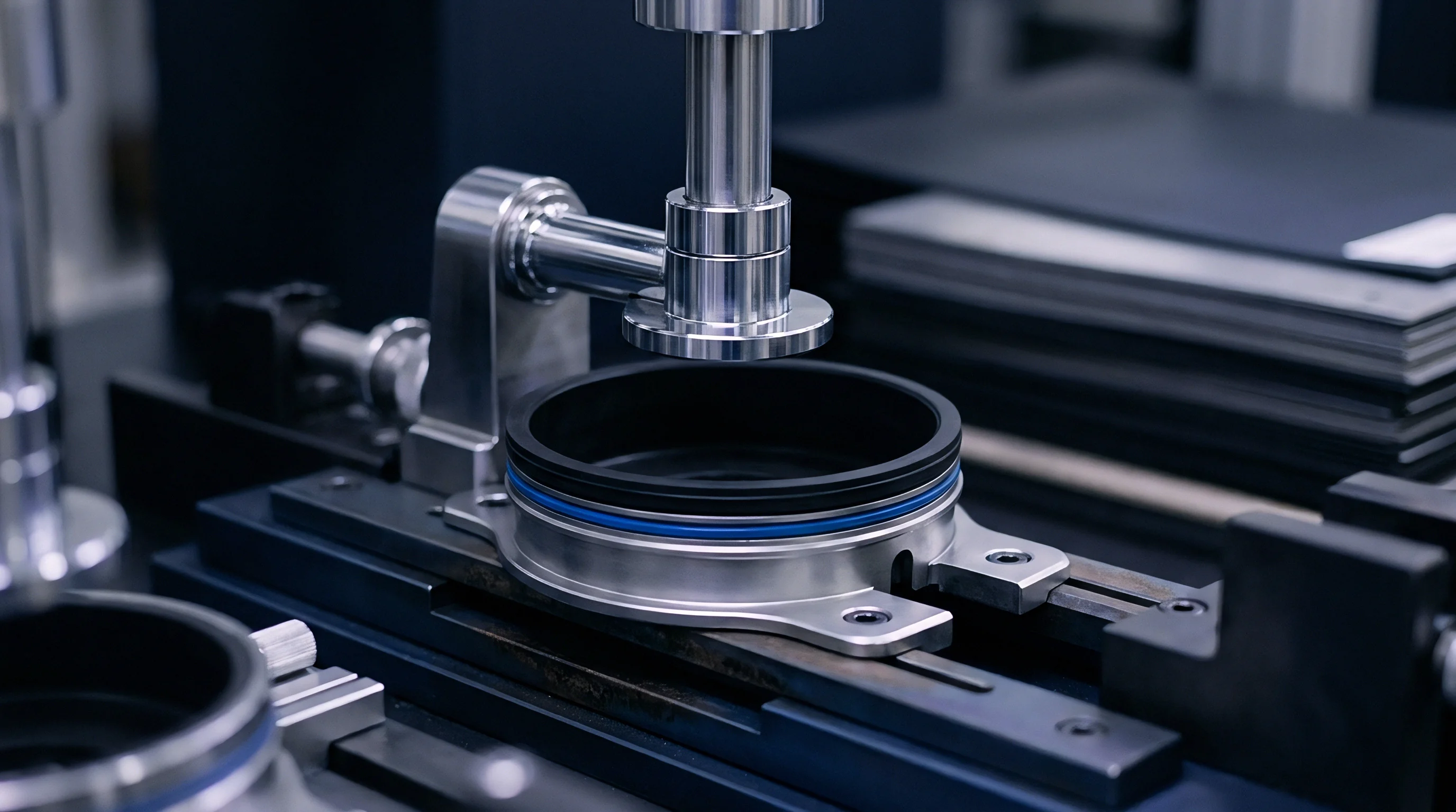
Thermal Processing Schedules for Carbide Refinement
Achieving optimum hardness and dimensional stability in high-alloy tool steels requires rigorous heat treatment control. Vacuum furnace processing must incorporate multi-stage preheating, precise austenitizing temperature control, high-pressure gas quenching, and multiple tempering cycles. Deep cryogenic treatment integrated between quench and temper steps further refines matrix microstructure and eliminates retained austenite.
During austenitizing, high temperatures dissolve secondary carbides into the iron matrix, enriching it with carbon and alloy elements required for martensite formation. Excessively high austenitizing temperatures cause rapid grain growth and dissolve primary carbides, embrittling the steel. Low austenitizing temperatures leave insufficient carbon in solution, resulting in lower matrix hardness post-quenching.
High-pressure nitrogen gas quenching must achieve a cooling rate fast enough to bypass soft pearlite and bainite transformations, yielding a fully martensitic structure containing un-dissolved primary carbides.
Deep cryogenic treatment (-196 degrees Celsius) in liquid nitrogen transforms nearly all retained austenite into fresh martensite. Retained austenite is unstable and degrades into un-tempered martensite over time under operational stress and temperature fluctuations, causing unpredictable dimensional growth in precision die inserts. Following cryogenic exposure, triple tempering at temperatures above 500 degrees Celsius relieves quenching stresses, precipitates fine secondary carbides, and tempers newly formed cryogenic martensite to target working hardness levels between 60 HRC and 64 HRC.
| Material Grade | Processing Route | Austenitizing Temp (°C) | Cryogenic Cycle | Retained Austenite (%) | Transverse Charpy Impact (J) | Target Hardness (HRC) |
|---|---|---|---|---|---|---|
| AISI D2 | Ingot Cast | 1030 | None | 14.2 | 11.5 | 60 – 61 |
| AISI D2 | ESR | 1030 | -80 °C (Cold Box) | 4.5 | 18.2 | 60 – 61 |
| AISI M2 | Ingot Cast | 1210 | None | 11.8 | 14.0 | 62 – 63 |
| CPM 10V | PM | 1070 | -196 °C (LN2) | < 1.0 | 26.5 | 62 – 64 |
| Vanadis 4 Extra | PM | 1060 | -196 °C (LN2) | < 1.0 | 42.0 | 60 – 62 |
| Bohler K390 | PM | 1070 | -196 °C (LN2) | < 1.0 | 31.0 | 62 – 64 |
Standard tooling procurement prints require explicit drawing notes to enforce microstructural compliance. Standard specifications must require certified metallographic reports verifying that delivered material meets explicit ASTM E1268 criteria before machining begins.
- Raw Material Certification mandates that every raw bar shipment include a heat-specific mill certificate detailing melt process, chemical composition, and non-destructive ultrasonic verification per SEP 1921 Group 3 Class E/e.
- Microstructural Banding Limit defines that tool steel stock must not exceed ASTM E1268 Anisotropy Index AI = 1.25 for ESR grades or AI = 1.08 for PM grades when evaluated across 20 representative fields of view.
- Cryogenic Processing Protocol requires continuous immersion deep cryogenic treatment at -196 degrees Celsius for a minimum hold time of four hours between quenching and first tempering.
- Hardness Uniformity Standard specifies that finished die inserts must fall within a narrow hardness band of +/- 0.5 HRC across all functional working faces, verified by micro-Vickers testing.
Purchase order clause 8.3: Tool steel bar stock exhibiting ASTM E1268 degree of banding values above 0.20 will be rejected at supplier expense, including reimbursement for preliminary sectioning and metallographic qualification costs.
Incorporating explicit microstructural metrics into supply contracts transfers quality ownership back to specialty steel distributors, preventing sub-standard, heavily segregated tool steel from entering the die manufacturing stream.


Claim
Commercial risk allocation between cell manufacturers, press toolmakers, and raw material distributors hinges on establishing clear responsibility boundaries for tool performance. Premature die failure disrupts cell assembly lines, creates scrap cell housings, and generates substantial financial losses. When a high-aspect blanking punch splits during a production run, toolmakers typically point to material defects in the steel, while steel distributors blame improper press alignment, inadequate lubrication, or flawed heat treatment profiles.
Resolving warranty disputes requires clear technical evidence linking tool failure directly to quantifiable material deficiencies. If metallographic analysis of a fractured punch reveals continuous primary carbide bands running along the fracture surface, with ASTM E1268 Anisotropy Index values exceeding contractually agreed limits, responsibility settles squarely on the material supplier. Conversely, if the steel exhibits a clean, isotropic PM microstructure while hardness testing reveals excessive retained austenite from skipped cryogenic steps, liability shifts to the heat treatment vendor.

Non-Destructive Verification and Microstructural Acceptance Thresholds
Implementing incoming inspection protocols protects tooling budgets by catching microstructural defects before incurring expensive machining and heat treatment costs. Tooling buyers cut material qualification coupons from bar ends upon arrival, submitting them for immediate metallographic evaluation and microhardness mapping. Combining destructive coupon testing with non-destructive ultrasonic scanning provides full coverage across raw material inventory.
Ultrasonic inspection utilizes high-frequency sound waves to detect internal discontinuities, inclusions, and heavy centerline segregation. High-resolution phased array ultrasonic testing (PAUT) maps spatial density variations along the longitudinal axis of large tool steel bars. PAUT scans identify macro-segregation zones that correlate with high primary carbide concentrations, allowing quality control inspectors to isolate defective bar segments before allocating stock to critical punch fabrication jobs.
Establishing clear numerical acceptance thresholds inside raw material purchasing agreements eliminates commercial ambiguity. Procurement contracts must tie payment milestone releases to successful incoming inspection pass receipts. By defining precise mathematical limits for Anisotropy Index, degree of banding, and peak-to-valley microhardness variance, cell manufacturers create an unassailable technical basis for rejecting sub-standard tool steel shipments.

Commercial Risk Boundaries in Tooling Procurement Contracts
Tooling NRE contracts must clearly delineate scope and risk boundaries across all stages of die design, material sourcing, fabrication, and press line bring-up. When cell manufacturers outsource stamping die production to turnkey tooling vendors, contract language must specify whether the vendor assumes full liability for material performance or simply acts as a machining contractor following buyer-mandated steel specifications.
Semis-custom and custom tooling deals require structured warranty terms covering minimum stroke guarantees. Standard clauses mandate that die inserts meet or exceed a defined stroke count—such as five million strokes for PM tool steel punches stamping 3004 aluminum—before requiring regrinding or re-coating. If a tool fails prematurely due to microstructural carbide segregation verified by an independent metallurgical audit, the contract should compel the tool steel supplier or tooling vendor to replace damaged inserts at zero cost, while compensating the cell maker for press downtime and scrapped cell components.
Defending these financial claims requires rigorous documentation. Quality teams must retain cut-off coupons, mill certs, heat treatment furnace logs, PAUT scan data, and post-mortem metallographic failure reports in a centralized compliance file. This technical dossier transforms subjective commercial arguments into an undeniable record of material non-compliance, ensuring prompt financial recovery when material failures disrupt cell production plans.
Does the industry require a standardized, real-time ultrasonic scanning protocol capable of quantifying carbide band density in heavy bar stock prior to sectioning, or will toolmakers remain reliant on destructive end-coupon metallography to police material quality?