Isothermal Terminal Calibration for High-Current Cell Testing
Active isothermal terminal calibration eliminates contact heat injection during high-current cell testing, preventing false capacity and cycle life data.


Junction
High-current cell qualification depends on steady thermal control inside environmental chambers, yet chamber air alone cannot regulate the cell-to-tester connection point. When cycling large-format prismatic LFP cells at 300 amperes or running pouch cells through 5C discharge pulses, contact resistance at the terminals generates intense localized heat. An interface impedance of just 50 micro-ohms produces 4.5 watts at a single post under a continuous 300A load.
Without active thermal control directly at the terminals, this heat conducts straight into the tabs and current collectors, driving internal tab temperatures 12 to 18 degrees Celsius above the chamber ambient.
Standard test setups monitor ambient chamber probes or mid-can skin thermistors, missing the steep thermal gradients between the cell core and the busbars. Conductive heating through positive and negative posts thins the electrolyte locally and accelerates lithium-ion transport around the tabs. The resulting drop in local internal resistance props up discharge voltage plateaus and conceals capacity fade during high-rate cycling.
On cold cycles, the inverse occurs: heavy, unheated copper busbars pull heat out through the posts, causing uneven lithium plating near the collectors that bears little resemblance to actual field performance.
A terminal contact resistance of 50 micro-ohms under a 300-ampere discharge continuous current creates a localized thermal injection of 4.5 watts directly into the internal current collectors.
Isothermal terminal calibration holds the fixture contact points at the exact boundary temperature assigned to the cell body. This requires separate temperature sensing at each terminal alongside active heating or cooling hardware that offsets ohmic losses at the busbars. If a test ignores these boundary conditions, the resulting rate-capability and cycle-life numbers document the thermal properties of the fixture rather than the cell’s native electrochemistry.

Thermal Coupling Dynamics at High Amperage
Heat generated during high-amperage cycles splits into bulk electrochemical heat and localized ohmic contact losses. Entropic shifts and bulk impedance distribute heat relatively evenly through the jellyroll, but the terminal connections behave as concentrated sources or sinks. Copper positive posts and aluminum negative posts also conduct heat at distinctly different rates, establishing an asymmetrical thermal gradient across the top cover.
caption>Thermal Flux and Contact Mechanics at Cell Terminals
Discrepancies in cell-to-cell data are often blamed on chemistry flaws when the actual culprit is contact wear in the fixture. Over several hundred cycles, copper busbars oxidize, spring packs fatigue, and pneumatic clamping pressures drift off calibration. As contact resistance rises, terminal temperatures climb with it, skewing degradation rates across the upper cell core.
Forced-air chamber circulation is frequently expected to strip this heat away, but air movement does not counteract direct conduction across the terminal interface.
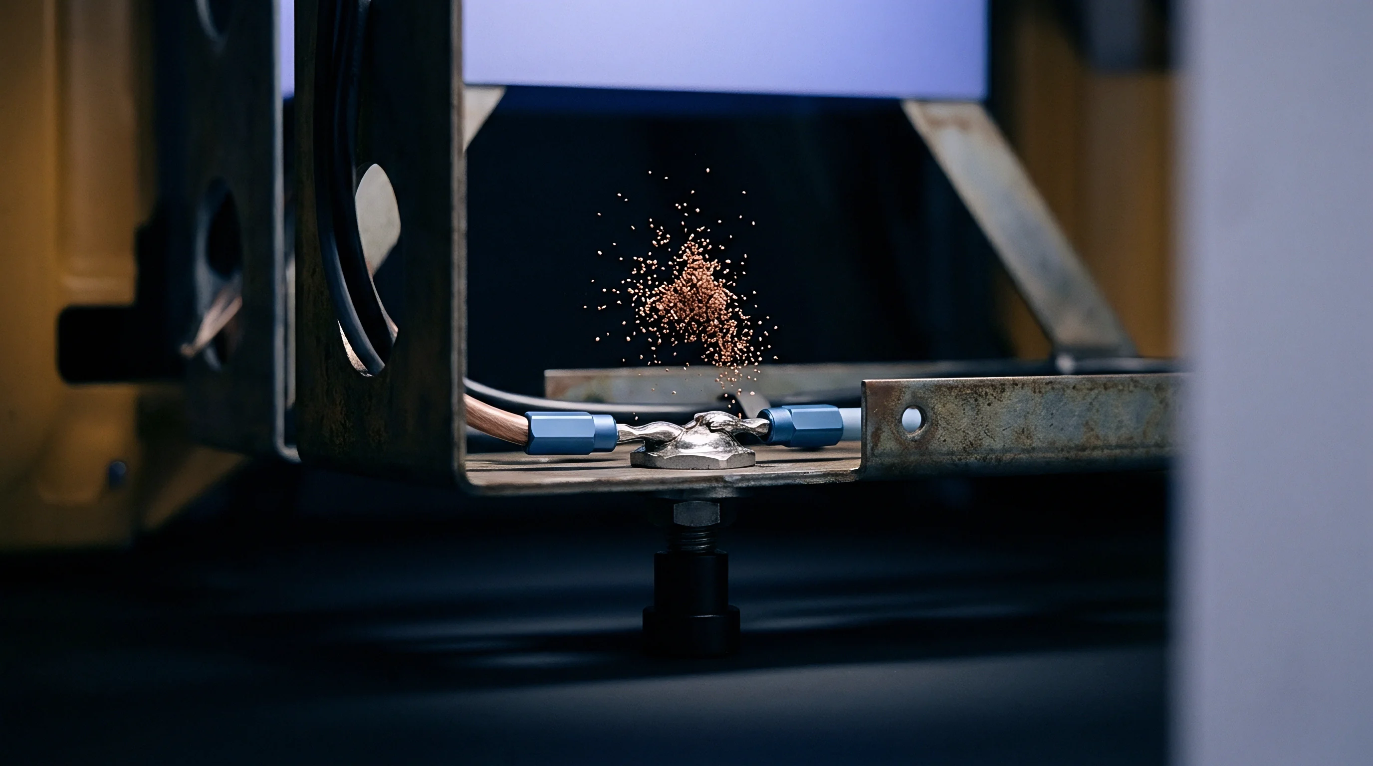
Clamp
The mechanical clamp is the direct physical link between the cell terminal and the cycler’s power electronics. Basic bolted or spring-loaded clamps introduce variable contact resistances that shift with torque, temperature, and surface oxidation. To preserve isothermal boundaries, advanced fixtures integrate active thermal control loops directly inside the clamping jaws.
These assemblies use gold-plated oxygen-free copper or beryllium-copper contact blocks backed by Peltier thermoelectric elements or internal channels plumbed to recirculating chillers.
Active thermal clamping shields the terminal interface from both internal I2 R heating and drafts within the chamber. Temperature sensors embedded within 1.5 millimeters of the contact face feed dedicated PID loops, keeping the clamp block within plus or minus 0.2 degrees Celsius of the cell surface target. The moment current ramps, the loop compensates for contact heating by accelerating coolant flow or driving Peltier heat absorption.
caption>Isothermal Control Methods for High-Current Testing Fixtures
Isothermal operation requires continuous measurement of interface impedance during test runs. A four-wire Kelvin layout reads voltage drop directly across the terminal-clamp boundary, isolating contact resistance from the cell’s internal impedance.
- Micro-ohm impedance monitoring tracks contact resistance throughout multi-week cycling schedules, triggering automated test pauses when contact resistance exceeds 30 micro-ohms.
- Pneumatic actuation systems deliver uniform, repeatable clamping force across all test channels, eliminating human error inherent to manual torque wrenches.
- Direct-contact thermistor arrays map temperature gradients along the tab length, verifying zero thermal flux between the internal current collector and external busbar.
- Dielectric isolation barriers prevent parasitic electrical paths through thermal management fluid loops, protecting instrument resolution.
International standard test protocols fail to specify terminal heat-sinking limits, allowing test facilities to report artificially extended cycle lives achieved through localized terminal cooling.
Surface preparation remains critical. Aluminum terminals oxidize quickly in open air, driving up contact resistance and causing steep thermal spikes during high-rate charging. Automated mechanical brushing or gold-flashed contact surfaces keep interface resistance stable across multi-month test campaigns.
Relying on bolted fixtures without continuous torque verification guarantees resistance drift, making long-term degradation comparisons unreliable.


Distortion
Uncontrolled terminal temperatures alter local electrochemical kinetics, skewing data across capacity, rate capability, and cycle life. Elevated temperatures lower charge-transfer resistance across the solid electrolyte interphase and speed lithium-ion diffusion in graphite anodes. When unmanaged heat warms the upper core during discharge, that section operates at a lower internal resistance and higher effective C-rate than the cooler base.
This uneven current distribution triggers localized lithium plating on subsequent charges, creating premature capacity knees and failure modes that misrepresent the cell’s actual design.

Where Is Isothermal Drift Masked in Test Reports?
Test reports frequently present smooth discharge curves and steady capacity retention plots that conceal sharp internal gradients. Unmitigated terminal heating artificially boosts high-rate discharge capacity by keeping core temperatures high enough to delay the lower cut-off voltage. Conversely, during cold tests down to minus 20 degrees Celsius, heavy unheated leads pull heat from the tabs, bringing on transport-limited cut-offs well before the core has discharged.
A thermal gradient of five degrees Celsius across a prismatic cell mantle induces a twenty percent imbalance in local current density distribution across internal current collectors.
The mismatch between uncalibrated laboratory test benches and field pack conditions tends to emerge late during module validation. Production battery packs use welded busbars and manage heat across cell faces rather than through individual terminal clamps. If cell qualification relied on passive heat-sinking through the test leads, reported cycle life can overestimate real-world pack endurance by up to 35 percent.
caption>Performance Metrics Distortion Under Thermal Terminal Gradient
Thermal gradients also distort electrochemical impedance spectroscopy performed on test channels. High-frequency intercepts shift and charge-transfer arcs warp whenever temperature varies across the cell structure, corrupting state-of-health algorithms. When integrators overlook terminal calibration data, they absorb open-ended warranty risks based on inaccurate degradation curves.

Audit
Auditing test dossier integrity requires reviewing fixture calibration logs, sensor placements, and raw temperature channel data. UN 38.3 T.2 transport safety tests and IEC 62619 electrical performance standards require thermal monitoring, but test standards rarely require labs to detail terminal boundary conditions. An audit establishes whether logged cell temperatures reflect ambient chamber conditions, skin surface readings, or genuine terminal equilibrium.
A thorough review follows test data from raw sensor channels through to the final summary. For high-current cell families, auditors look for dedicated terminal temperature channels recorded alongside voltage and current.
- Review laboratory ISO/IEC 17025 accreditation scopes to confirm specific capability for high-current thermal boundary control.
- Inspect raw time-series CSV data files to verify that terminal temperature recordings remain within plus or minus 1.0 degree Celsius of the target ambient temperature during 3C or higher discharge steps.
- Cross-check contact resistance calibration logs for four-wire Kelvin sensing fixtures used during the specific batch run.
- Verify terminal connection hardware specifications, ensuring busbar thermal mass and active cooling mechanisms match disclosed laboratory procedure manuals.
- Validate cut-off voltage triggers against instantaneous terminal temperature spikes to confirm thermal protection safety stops were not tripped artificially.
Gaps often appear when comparing third-party cycle-life reports against cell manufacturer datasheets. Without documented terminal calibration, test dossiers remain vulnerable under UN 38.3 test summary requirements if transport authorities challenge the thermal boundary conditions used during thermal shock and short-circuit evaluations.
Under Clause 6.2 of IEC 62619, functional safety testing requires rigorous control over environmental boundaries. Missing documentation on terminal thermal stabilization can justify rejecting factory qualification dossiers during customs clearance inspections or UL 1973 system certifications.
Exposure
Qualifying high-current cells against flawed thermal data passes major financial risk downstream to pack manufacturers and system integrators. When a cell rated for 3,000 cycles at 2C continuous discharge degrades after 1,800 cycles in the field, warranty liability falls on whoever approved the specification dossier. If initial testing relied on terminal heat sinking that suppressed degradation, warranty claims often collapse once the manufacturer attributes the failure to thermal differences in the pack enclosure.
Agreements between cell vendors and system buyers need clear terminal calibration requirements for pre-production qualification and batch acceptance. Contracts that omit interface resistance limits and terminal temperature tolerances allow vendors to run optimistic test setups that production modules cannot replicate.
Field recall expenses from premature capacity loss or internal short circuits driven by thermal stress easily wipe out the savings from lower unit costs. Underwriters insuring large-scale storage installations increasingly require audited test dossiers documenting fixture thermal controls before binding policies.
International regulatory bodies have yet to amend safety standards to require active terminal temperature calibration during high-rate transport and functional safety testing.