Quantifying Deflagration Overpressure Dynamics in Closely Spaced Outdoor Utility Battery Storage Bays
Utility BESS deflagration overpressure depends on off-gas burning velocity and corridor blockage turbulence rather than open-air venting calculations.

Flame
When lithium-ion battery modules enter thermal runaway, they discharge substantial volumes of combustible off-gas. Generation rates during catastrophic cell breakdown depend heavily on chemistry, state of charge, and total stored energy. Lithium iron phosphate cells typically produce 80 to 140 liters per kilowatt-hour of nominal capacity, whereas fully charged high-nickel nickel manganese cobalt formulations yield 120 to 220 liters per kilowatt-hour.
Gas evolution is rapid, hitting peak volumetric flow rates within tens of seconds of initial cell venting.
This rapid vapor release dictates early hazard mitigation.

Composition and Reactivity of off Gas
Pyrolysis products from failing cells consist mainly of carbon monoxide, hydrogen, methane, and ethylene, alongside non-flammable carbon dioxide and vaporized carbonate solvents. Hydrogen concentration drives overall combustion reactivity. Off-gas from lithium iron phosphate cells typically contains 20 to 35 percent hydrogen by volume, while high-nickel formulations can surpass 40 percent under extreme thermal stress.
Elevated hydrogen levels depress the lower flammability limit in air, broadening the combustible envelope inside an enclosure.
Lithium iron phosphate off gas mixtures containing thirty percent hydrogen by volume exhibit deflagration indices exceeding one hundred ten bar meters per second.
Total gas yield scales directly with installed cell capacity.
Gas composition varies across different thermal regimes.

Laminar Burning Velocity and Gas Index
Fundamental combustion rates govern how fast a deflagration front moves through an enclosure. Under stoichiometric conditions in air, the laminar burning velocity of pure lithium-ion off-gas spans 0.45 to 0.85 meters per second, placing the mixture in gas group IIB or IIB+H2 on standard explosion scales. The deflagration index, or gas constant, defines the maximum normalized pressure rise rate inside a closed vessel.
High hydrogen fractions are what accelerate flame propagation.
| Chemistry Type | State of Charge | Gas Yield (L/kWh) | Hydrogen Vol % | Deflagration Index (bar·m/s) |
|---|---|---|---|---|
| Lithium Iron Phosphate | 100% | 110 | 28% | 115 |
| Lithium Iron Phosphate | 80% | 85 | 22% | 92 |
| NMC 811 | 100% | 195 | 42% | 168 |
| NMC 622 | 100% | 160 | 35% | 138 |
| Data derived from standard vessel explosion tests conducted at 25 degrees Celsius initial temperature and atmospheric pressure. | ||||
Applying generic methane properties to these calculations underestimates the rate of pressure rise. Standard vent design methods predicated on lower deflagration index values yield undersized relief panels. Accurate sizing demands empirical burning velocity data corresponding to the specific cell chemistry and maximum operational state of charge.
Whether cell venting behavior in nitrogen-purged container spaces reflects open-air tube furnace metrics remains an open research question.

Geometry
Layout design in utility-scale energy storage dictates how expanding vapors dissipate. Sites typically arrange walk-in enclosures, modular cabinets, or containerized systems in tightly spaced rows, with clearances between adjacent side walls kept between 1.5 meters and 3.0 meters to optimize footprint and control cabling costs. This proximity limits free-field relief when an explosion panel functions.
Venting mechanisms are sized to discharge internal pressure safely.
Blockage Ratio and Turbulence Generation
Internal structures and dense racking impede fluid flow during a venting event. The blockage ratio ~ the portion of cross-sectional area taken up by battery modules, HVAC ducting, power conversion units, and framing ~ drives flow behavior. High blockage ratios generate intense turbulence as unburned gas is forced through narrow gaps ahead of the flame front, expanding the flame surface area and accelerating combustion.
Internal obstructions convert laminar flow into turbulent flame acceleration.
Flame speed scales directly with obstruction density. In an open enclosure, flame propagation stays close to the laminar burning speed. Through a dense rack array where blockage ratios exceed 0.4, localized flame speeds can surge past 50 meters per second, generating peak overpressures far higher than static venting models predict.

Corridor Confinement in Closely Spaced Bays
Narrow corridors between outdoor enclosures form semi-enclosed spaces that trap vented gases. When a container discharges its deflagration panel into a 2-meter alley, hot gas and unburned fuel mix with ambient air in the confined space. Accumulating gas in the bay then ignites on contact with the flame front, producing a secondary external explosion.
Confinement within these alleys amplifies peak pressure loads.
- Obstruction Concentration High rack packing density inside walk-in enclosures increases localized flow turbulence during gas expulsion.
- Corridor Width Reduction Spacing enclosures closer than two meters holds vented gas within the bay alleyway, raising secondary explosion yields.
- Vent Opening Direction Directing explosion vent panels toward facing container sidewalls increases shock wave reflection forces.
- Cable Trench Channels Underground conduit runs act as unvented migration paths for heavy hydrocarbon vapor accumulations.
Narrow clearance channels between rigid enclosures act as flame nozzles that transform low speed deflagrations into directional blast jets.
External burning inside the corridor creates backpressure against the venting container, slowing discharge through the panel and driving up internal overpressure. Designing outdoor installations under free-field assumptions ignores the hydraulic resistance imposed by adjacent container walls.
Outdoor separation beyond two meters does not inherently eliminate overpressure hazards if venting orientation promotes localized confinement.


Overpressure
Peak transient pressures during enclosed gas combustion depend on internal flow resistance. Deflagration dynamics follow non-linear paths determined by vent opening pressure, structural enclosure strength, and burning rates. Standard relief calculations rely on empirical formulas developed for simple spherical or cylindrical volumes; rectangular enclosures housing dense battery racks produce pressure peaks that deviate significantly from those models.
Reflected shock waves significantly increase effective wall loading.

Is NFPA 68 Vent Sizing Valid for Outdoor Confinement?
Standard venting equations assume unobstructed discharge into open air. NFPA 68 provides formulas for required vent area based on enclosure volume, static release pressure, and targeted peak reduced overpressure. These formulas do not account for backpressure caused by opposing walls within three meters of the discharge plane.
When panels vent into a restricted bay, the expelled cloud ignites under partial confinement, sending a pressure wave back toward the opening. This backpressure reduces the effective vent discharge coefficient by 30 to 50 percent, driving internal overpressure beyond initial design calculations.
- Determine Gas Release Volume Quantify total flammable gas yield based on full module thermal runaway under maximum state of charge assumptions.
- Calculate Internal Free Volume Subtract battery rack, inverter, and structural volume from total enclosure gross volume to establish net gas space.
- Evaluate Corridor Blockage Model external alleyway dimensions and neighboring wall obstructions to determine discharge backpressure coefficients.
- Simulate Blast Wave Reflection Compute combined incident and reflected dynamic pressure loads on facing container structural panels.
Failure to account for acoustic resonance inside vented bay cavities invalidates standard explosion relief area calculations under NFPA 68.
Dynamic Load Characterization on Adjacent Enclosures
Shock waves and expanding gas clouds from relief vents impinge directly on adjacent units. The total pressure on a neighboring wall combines the incident wave and the reflected wave. Reflected pressure varies with the angle of incidence and structural stiffness; head-on impact against a rigid steel panel can double or triple the incident pressure value.
Structural sidewalls deform or yield when limits are exceeded.
| Separation Distance (m) | Peak Incident Pressure (kPa) | Peak Reflected Pressure (kPa) | Positive Phase Impulse (kPa·ms) | Wall Deformation Risk |
|---|---|---|---|---|
| 1.0 | 45.0 | 112.0 | 380 | Severe Plastic Buckling |
| 1.5 | 28.0 | 64.0 | 210 | Permanent Yield Strain |
| 2.0 | 18.0 | 38.0 | 130 | Elastic Deflection Limit |
| 3.0 | 9.5 | 19.5 | 65 | Negligible Deformation |
| 5.0 | 4.2 | 8.0 | 28 | Safe Operating Margin |
In a 2.5 megawatt-hour container experiencing multi-module thermal runaway, off-gas accumulates until ignition vents top-mounted panels at a static pressure of 10 kilopascals. If neighboring containers are 1.5 meters away, the plume hits the opposing wall at peak incident pressures of 28 kilopascals, producing reflected loads of 64 kilopascals. Standard steel sidewalls rated for 15 kilopascals fail structurally, risking cascading damage across the array.
Peak pressure pulses arriving at adjacent container sidewalls drop significantly once the clearance gap exceeds four meters.


Mitigation
Structural protective elements absorb and redirect explosive energy generated during catastrophic thermal events. Effective explosion protection strategies combine fast-acting physical relief mechanisms with directional barrier walls. Sizing relief vents without accounting for structural deflection leads to premature container rupture.
Maintaining deflection limits avoids structural collapse.
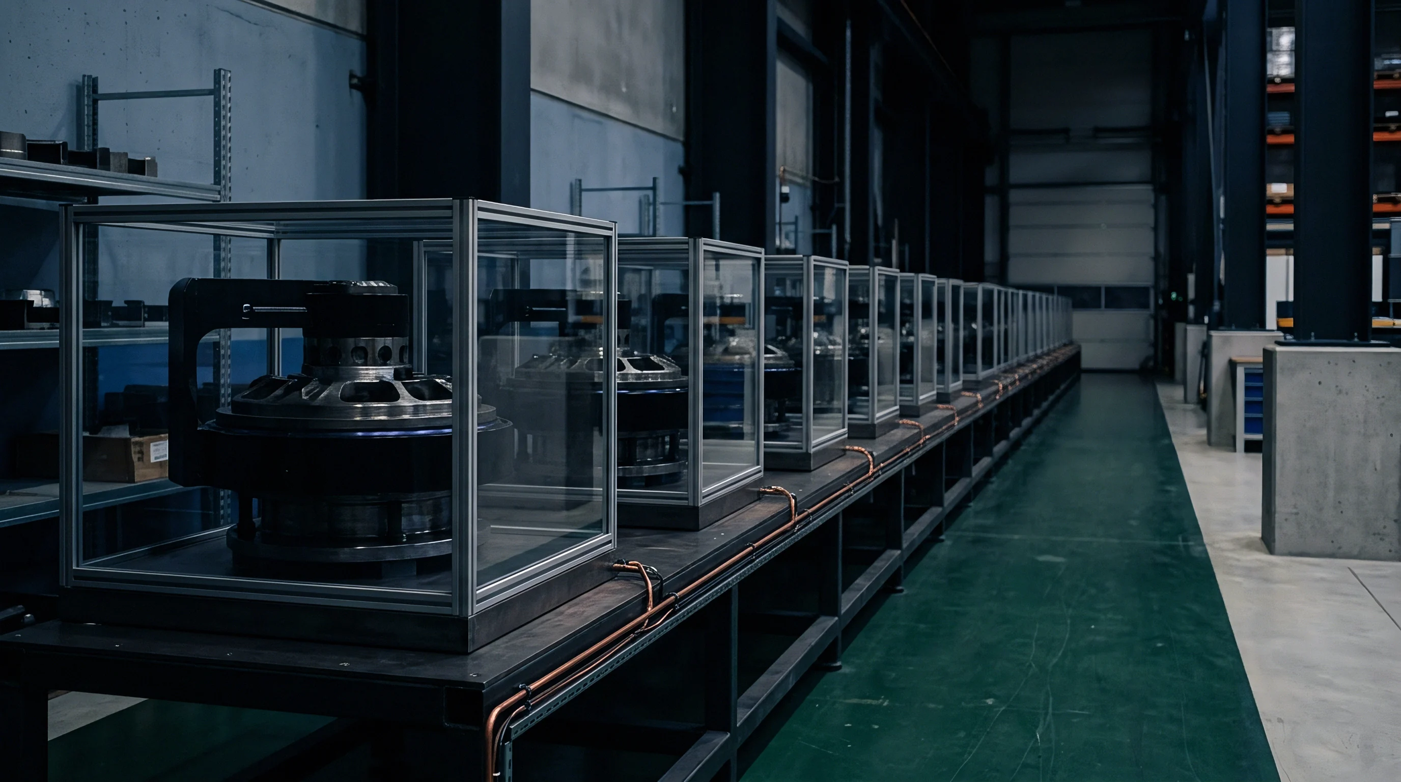
Deflagration Vent Panels and Ducting Efficiency
Pressure relief covers engineered for battery enclosures open at low activation thresholds to prevent container rupture. Typical burst pressures for membrane panels or re-closing vent hatches range from 5 to 15 kilopascals. Low inertia vent panel construction ensures rapid opening times, reducing initial pressure spikes.
Vent ducts installed to route explosion products away from access corridors introduce flow resistance that reduces overall venting efficiency.
Activation thresholds govern panel release speed.
Duct length, bends, and outlet discharge guards impose frictional resistance on outgoing burning gases. Each 90-degree duct elbow reduces effective vent capacity by approximately 15 percent. Long exhaust duct runs increase the effective mass of air that must be accelerated out of the channel, elevating internal peak overpressure inside the enclosure.
Deflagration panels engineered for indoor enclosures frequently fail to burst cleanly when subjected to external backpressure from adjacent blast waves.
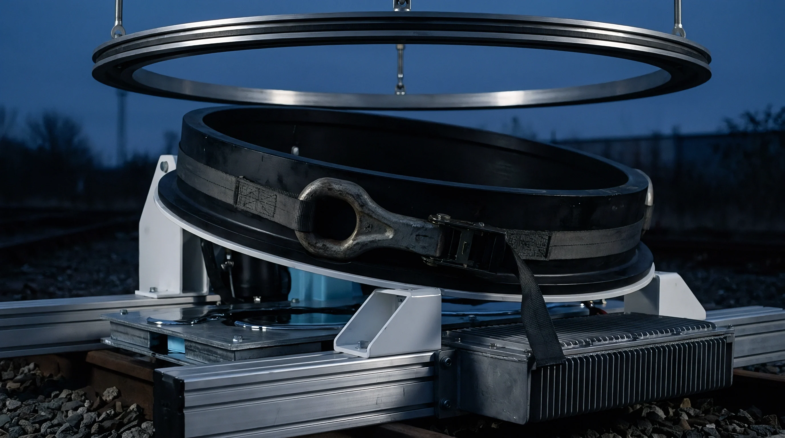
Barrier Walls and Deflection Mechanics
Reinforced blast shields positioned between container rows block direct flame jet impingement. Concrete, masonry, or composite blast walls dissipate kinetic energy from shock waves before forces reach neighboring enclosures. Barrier wall geometry must extend beyond the line of sight between adjacent vent panels to prevent flame wrapping around wall edges.
Wall thickness directly alters energy absorption and deformation rates.
- Low Mass Vent Membranes Ultra-lightweight panel materials open within milliseconds, minimizing early internal pressure buildup.
- Vertical Exhaust Deflectors Upward-facing discharge ducts direct high-velocity flame jets away from adjacent ground-level equipment rows.
- Interlocking Barrier Panels Modular blast walls absorb structural strain through controlled plastic deformation during peak impulse loading.
- Flame Arresting Vent Assemblies Mesh matrix flame quenchers cool exiting combustion gases, preventing external cloud ignition in corridors.
Integration of blast barrier structures alters airflow patterns within the utility enclosure yard. Site layouts featuring solid barrier walls require higher venting clearances above the containers to compensate for localized stagnation zones created by the barriers. Designers must balance thermal dissipation needs during standard operation against blast redirection requirements during emergency deflagrations.
Standard procurement agreements referencing NFPA 68 Section 8.2 shift financial liability for structural enclosure buckling directly to the system integrator whenever field blockage ratios exceed theoretical design limits.


Indemnity
Commercial liability protection hinges upon verifying compliance with local explosion safety codes. Insurance underwriters require robust documentation proving that utility battery sites withstand maximum credible deflagration scenarios without off-site structural impacts. Operating warranties for utility scale BESS assets often depend on rigorous validation of explosion venting design parameters.
Physical site testing confirms calculated safety assumptions.
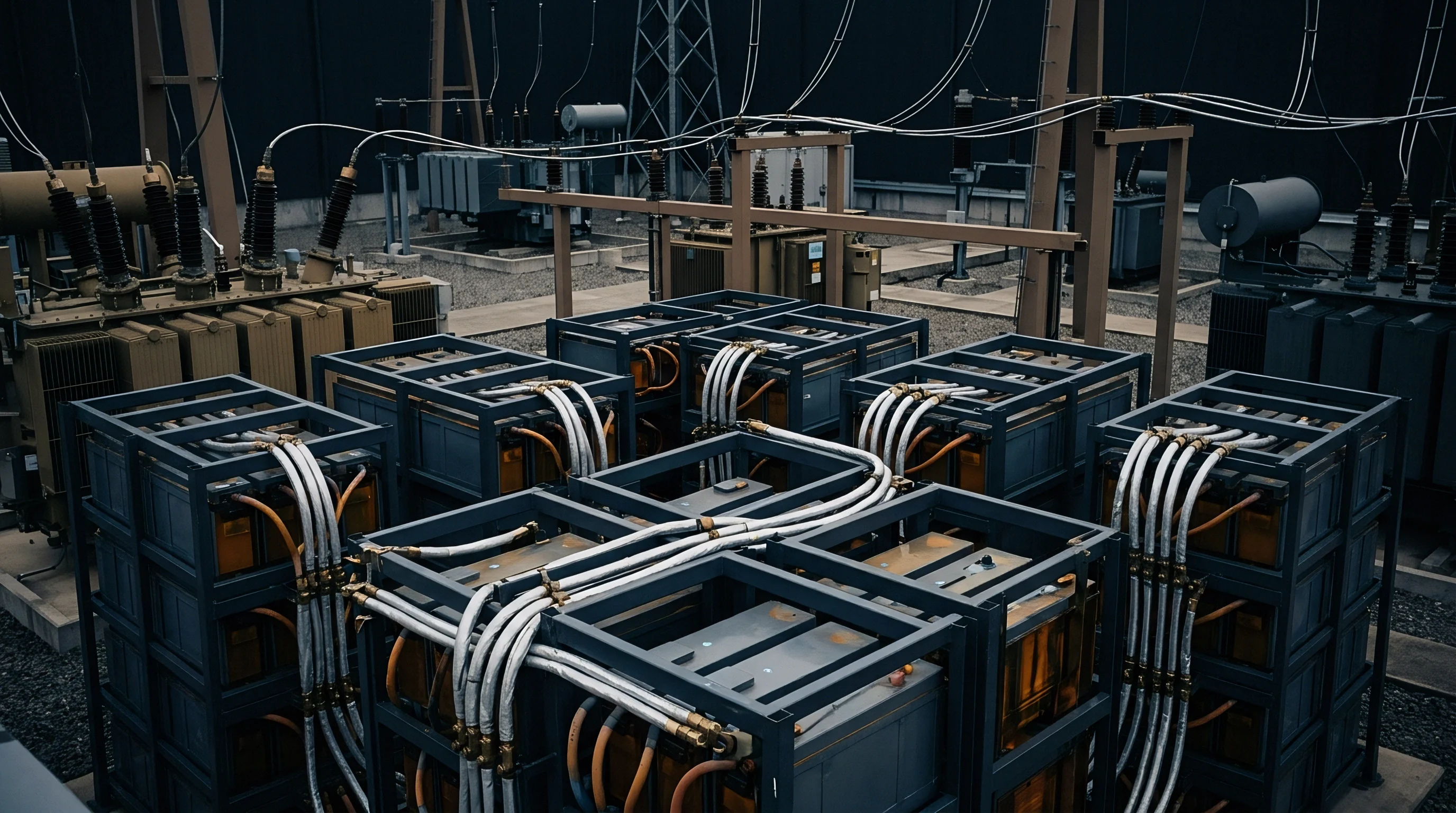
Proof of Safety File Integrity
Documented test evidence from recognized laboratories establishes the technical foundation for site risk acceptance. Standard UL 9540A unit-level and installation-level test reports supply empirical data regarding off-gas composition, volume, and burning characteristics. System integrators must compile these test outputs into a unified explosion safety dossier for local authority approval.
Uncertified venting layouts increase operational and regulatory exposure.
Generic cell compliance certificates do not satisfy jurisdictional requirements for assembled utility systems. Local fire marshals and site inspectors examine the interaction between cell off-gas rates, enclosure vent areas, and bay layout clearances. Discrepancies between tested cell configurations and installed battery pack density invalidate primary compliance filings.
Contractual Risk Allocation for Deflagration Hazards
Purchasing agreements delegate financial exposure between cell manufacturers, integrators, and site owners. Engineering procurement contracts clearly define liability limits associated with thermal runaway containment failure. Integrators assuming performance guarantees must verify that blast wave containment claims match physical site layout geometry.
| Document Type | Governing Standard | Primary Data Input | Compliance Function |
|---|---|---|---|
| Thermal Runaway Test Report | UL 9540A Cell/Module | Gas composition, yield, burning speed | Establishes baseline off-gas source terms |
| Explosion Vent Calculation | NFPA 68 | Vent area, opening pressure, Pred | Validates container structural protection |
| Site Explosion Risk Assessment | NFPA 855 | Separation distances, barrier rating | Defines bay separation safety margins |
| Field Certification File | AHJ Local Code | As-built site inspection records | Authorizes commercial site operation |
Incomplete explosion venting documentation leads directly to immediate insurance policy cancellation and project financing denial.