Quantifying Solid-State Battery Interfacial Voiding under Static Stacks
Static stack pressures above three megapascals prevent solid-state interfacial voiding during high C-rate stripping at ambient temperatures.


Creep
Solid-state pouch cells containing metallic lithium anodes experience rapid interfacial degradation when electrochemical stripping rates outpace the self-diffusion of metal atoms. Dynamic plastic deformation of the metal anode maintains intimate contact against rigid solid electrolyte separators during low-rate discharge. Elevated discharge current densities extract lithium atoms from the interface faster than mechanical flow replenishes the surface layer.
Lithium creep restores contact. When the local ionic stripping flux exceeds the mechanical deformation rate of the metal, vacancy accumulation nucleates microscopic voids along the solid electrolyte boundary.
Static stack architectures compound this degradation mechanism. Fixed mechanical gaps or rigid platens enforce constant external enclosure dimensions rather than constant compressive stress on active cell materials. As stripping proceeds, the local volume loss at the anode interface reduces effective local contact area.
The applied static force distributes over a shrinking physical contact area, concentrating mechanical stress onto remaining contact asperities. Micro-voids coalesce into delamination layers.
Interfacial void formation occurs when stripping current density exceeds the mechanical creep rate of metallic lithium at operating temperature.
Operating temperature alters this mechanical dynamic. At 20°C, the yield strength of metallic lithium stands near 0.8 MPa, limiting the rate of plastic flow into interfacial cavities. Raising the cell temperature to 60°C drops the yield strength significantly, enhancing plastic creep and suppressing void formation under equivalent stack forces.
Cold discharge cycles represent severe operational risks for static mechanical stacks. The failure chain under static stack restraint follows a predictable mechanical sequence.
- Vacancy Condensation Microscopic voids nucleate at localized stress minima along the solid electrolyte boundary when stripping current exceeds self-diffusion flux.
- Current Constriction Remaining metallic contact spots carry elevated localized current density, accelerating localized stripping rates and widening non-contact zones.
- Interfacial Delamination Planar propagation of merged micro-voids detaches large active areas of the metal anode from the ceramic separator matrix.
Interface impedance escalates rapidly. Localized current amplification at residual contact points creates non-uniform electric field distribution. During subsequent charge cycles, these high-current micro-domains act as preferential nucleation sites for lithium filament formation.
Void accumulation directly drives internal short-circuit vulnerabilities. Ignoring the dynamic yield strength of lithium metal during high-rate discharge under static fixtures results in localized current hot-spots, triggering micro-dendrite growth during subsequent charge cycles and shorting the cell.

Impedance
Separating interfacial contact loss from bulk electrolyte degradation relies on high-frequency AC spectroscopy collected across controlled temperature sweeps. Electrochemical impedance spectroscopy isolates transport steps by their characteristic relaxation time constants. Bulk ionic transport within sulfide or oxide solid electrolytes manifests as an ohmic intercept at high frequencies, typically above one megahertz.
Charge transfer across the solid electrolyte and metallic lithium boundary produces a distinct semicircle in the mid-frequency region between ten kilohertz and one hundred hertz.
Void formation alters this impedance response without shifting the bulk high-frequency intercept. As physical contact area shrinks, effective charge-transfer resistance increases proportionally to the lost contact surface fraction. Constriction resistance scales inversely.
The electric field lines crowd through remaining contact points, adding a pure geometric resistance term to the mid-frequency arc diameter. Operando X-ray computed tomography confirms that mid-frequency arc expansion mirrors physical void volume growth mapped at five-micrometer resolution.
| Static Pressure (MPa) | Discharge C-Rate | Contact Area Loss (%) | Interfacial Arc Increase (%) | Constriction Penalty (Ω·cm²) |
|---|---|---|---|---|
| 0.5 | 0.5C | 18.4 | 22.1 | 1.45 |
| 0.5 | 1.0C | 41.2 | 68.5 | 4.12 |
| 1.0 | 0.5C | 8.1 | 9.6 | 0.62 |
| 1.0 | 1.0C | 24.3 | 31.0 | 1.88 |
| 5.0 | 1.0C | 4.2 | 5.1 | 0.31 |
| 5.0 | 2.0C | 12.6 | 15.4 | 0.98 |
Quantifying void volume fractions requires continuous spectrum fitting during discharge transients. Static stack pressures below one megapascal fail to suppress void nucleation during 1.0C discharge pulses at ambient temperatures. Void formation accelerates capacity fade.
At five megapascals of static pressure, mechanical creep suppresses void propagation up to 1.0C rates, but creates severe structural demands on module enclosures. Dynamic equivalent circuit modeling uses an adjusted constant phase element to capture non-uniform current distributions across partially delaminated interfaces.
At 1.0 MPa static stack pressure and 1.0C discharge rate at 25°C, micro-void accumulation reduces effective interfacial contact area by 42% within 300 cycles.
Direct current resistance measurements using galvanostatic intermittent titration technique complement frequency-domain data. Voltage relaxation curves following high-current discharge steps reveal long time-constant overpotentials associated with localized lithium ion diffusion around interfacial voids. Combining real-time distribution of relaxation times analysis with static stack pressure tracking provides an early warning diagnostic for interfacial isolation before gross capacity drop occurs.
Whether operando impedance signatures can differentiate between lateral void spreading and vertical delamination at the solid electrolyte boundary remains unverified across commercial pouch sizes.


Frame
Mechanical containment hardware determines whether initial clamping force survives long-term module operation without dynamic active adjustment. Pack integration engineers face a trade-off between volumetric efficiency and structural compliance. Rigid end-plates bolted to fixed dimensions provide compact pack packaging but allow internal stack pressure to collapse during stripping steps.
Dynamic spring stacks maintain uniform compressive force across thickness variations, yet introduce severe volumetric and mass penalties to the battery enclosure.
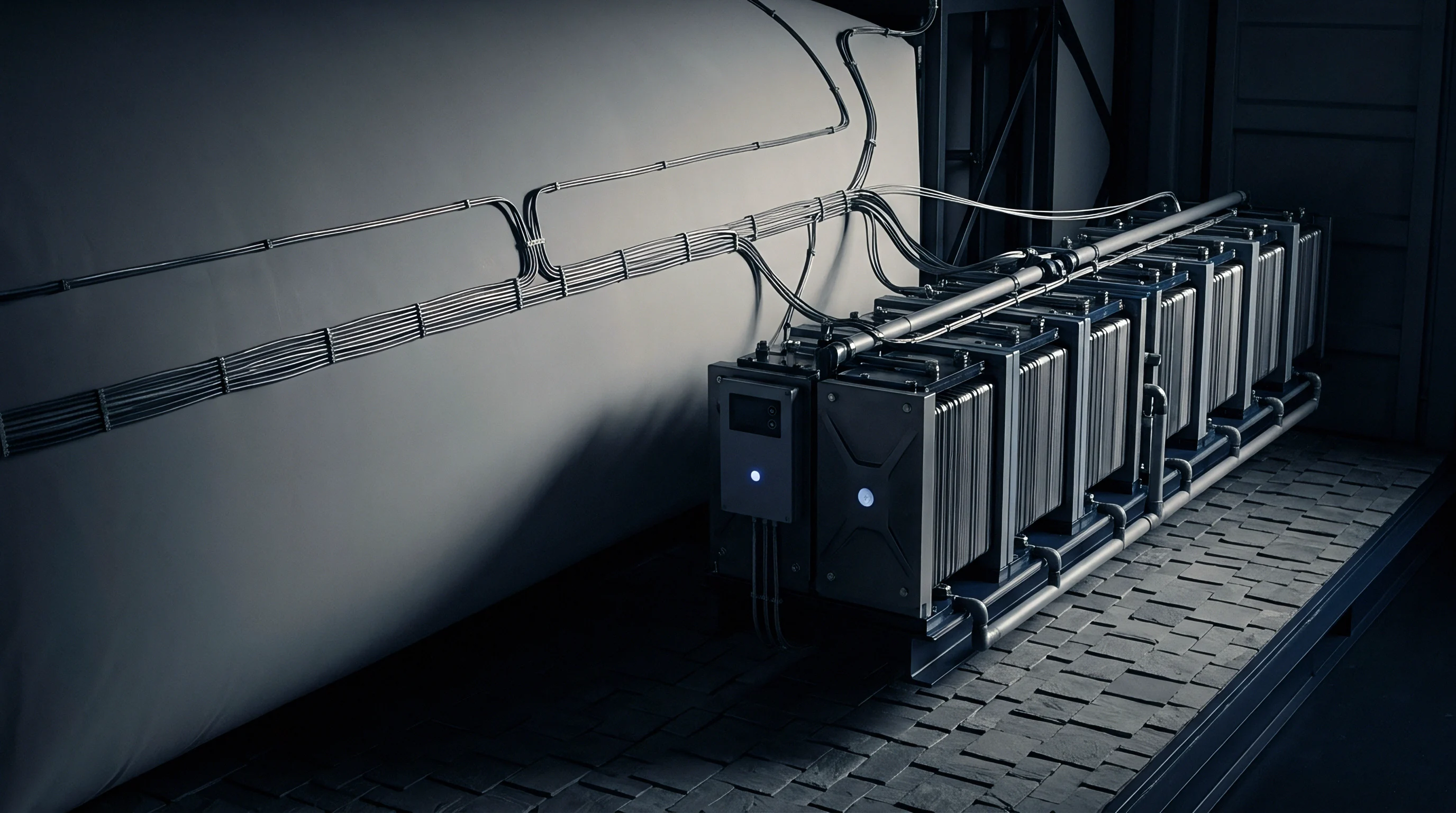
Are Dynamic Springs Justified over Static Platens?
Rigid structural plates maintain zero exterior volume expansion but allow interior interfacial stress to fall as lithium migrates during discharge. Solid-state pouch cells expand and contract in thickness by five to twelve percent between fully charged and fully discharged states, depending on anode chemistry and solid electrolyte thickness. In a rigid static frame, cell thickness contraction during discharge directly causes an internal pressure drop.
When stack pressure drops below the critical threshold for lithium creep, interfacial voiding accelerates rapidly.
Static platens preserve overall pack volume. Dynamic compression hardware uses Belleville disc springs, coil springs, or closed-cell elastomeric pads to maintain uniform loading. Elastomeric foams exhibit stress relaxation under continuous compressive load over multi-year operational lifetimes.
Polyurethane and silicone foam pads lose up to thirty percent of their initial load retention after one thousand thermal and mechanical cycles at 40°C. Spring-loaded mechanical frames deliver precise pressure regulation, yet consume valuable pack envelope space.
- Stack Pressure Retention Verify that total mechanical load drop remains under ten percent across the specified operating temperature range.
- Platen Deflection Limit Design end plates to restrict structural bending to less than fifty micrometers across the active pouch surface under maximum swelling.
- Thermal Expansion Match Select tie-rod materials with thermal expansion coefficients matched to the cell stack-up to prevent seasonal pressure drift.
| Containment Format | Volume Penalty (%) | Mass Penalty (%) | Pressure Drift over 1k Cycles (%) | Tooling Complexity Factor |
|---|---|---|---|---|
| Rigid Static End-Plates | 3.2 | 5.8 | -48.5 | 1.0 |
| Belleville Spring Stack | 18.5 | 14.2 | -4.2 | 2.4 |
| Elastomeric Compression Pad | 8.4 | 7.1 | -28.0 | 1.2 |
| Hydraulic Bladder Array | 22.1 | 19.6 | -1.5 | 3.8 |
Structural bending of static enclosure platens represents a secondary source of interfacial voiding. Flexural deformation of end-plates under central stack loads leads to non-uniform pressure distribution across the pouch cell area. Springs add significant mass penalties.
Edge regions maintain high compressive stress while central regions experience load relaxation, concentrating void formation at the cell core. End plates resist flexural deflection. Finite element analysis of end-plate geometry must constrain central deflection to prevent localized interface delamination.
Cell manufacturers frequently maintain that interfacial stack pressure loss over extended cycling stems entirely from pack-level housing creep rather than internal electrode volume degradation.

Decay
Quantitative tracking of stack load decay reveals an exponential drop in compressive force during initial cycling under fixed-gap containment structures. Consider a 50 Ah sulfide-based solid-state pouch cell installed in a rigid static fixture with an initial applied stack pressure of 5.0 MPa at 100% state of charge. The cell measures 200 mm by 100 mm with an active stack thickness of 5.0 mm.
Delithiation of the metal anode during a 1.0C discharge step removes a 15-micrometer layer of lithium across the active area, causing an unconstrained thickness reduction of 0.3% per cell layer.
In a rigid frame with zero structural compliance, this volume contraction reduces the total compressive force exerted against the load cell. Assuming an effective stack Young’s modulus of 2.5 GPa for the combined cathode, ceramic separator, and anode assembly, a total thickness drop of 12 micrometers across an 8-layer stack causes an initial stack pressure drop from 5.0 MPa down to 1.8 MPa at full discharge. Load cell logs confirm pressure decay.
The interfacial voiding rate scales non-linearly as compressive load drops below 2.0 MPa during the final 30% of discharge capacity.
Maintaining interface contact without active mechanical spring compensation demands operating temperatures that accelerate metallic lithium creep.
Evaluating this structural decay follows a strict four-step verification cadence on the bench testing channel.
- Mount the uncharged pouch cell between parallel rigid instrumented platens calibrated for micro-strain deformation.
- Apply initial target compressive load at ambient room temperature and record initial baseline platen displacement.
- Subject the assembly to fifty standard discharge-charge cycles while logging continuous load cell force metrics.
- Measure the residual stack pressure at full discharge to derive the stress relaxation coefficient of the solid interface.
Local current density spikes at asperities. The progressive decline in baseline stack pressure over multi-hundred cycle regimes reflects permanent structural rearrangement within the cell stack. Plastic deformation of surface micro-asperities during peak compression steps causes irreversible creep.
As a result, the peak stack pressure recorded at 100% state of charge drops on each successive cycle. By cycle 400, peak pressure at full charge falls from 5.0 MPa to 3.1 MPa, while minimum pressure at full discharge drops to 0.4 MPa. At 0.4 MPa, metallic lithium creep halts almost completely at 25°C, resulting in severe void accumulation and rapid capacity degradation.
Structural creep degrades stack tightness. Designing static enclosure platens with ultra-low thermal expansion materials preserves mechanical stack compression over wide operating temperature windows.

Clause
Procuring solid-state cells for integration into static pack architectures demands explicit contractual definition of mechanical testing conditions. Standard cell datasheets often report cycle life performance measured under hydraulic laboratory presses that maintain precise dynamic pressure control. Integrating those same cells into rigid, static module frames leads to premature capacity failure that falls outside traditional warranty provisions if stack pressure boundaries are undefined in supply contracts.
Procurement specifications must establish clear boundaries between cell-level volume change limits and module-level structural stiffness requirements. Warranty terms require physical boundary limits. If a cell vendor specifies performance at 3.0 MPa, the contract must define whether this figure represents a minimum static threshold at full discharge or an average dynamic pressure across the operating cycle.
Mechanical compliance dictates interface longevity. Defining this boundary determines liability for voiding-induced cell failures.
| Specification Parameter | Vendor Datasheet Claim | RFQ Required Boundary Condition | Verification Standard |
|---|---|---|---|
| Minimum Operating Stack Load | 2.0 MPa (Unspecified) | 2.0 MPa minimum at 0% SOC under static fixture | IEC 62660-3 Modified |
| Maximum Allowed Thickness Swell | < 8.0% total shift | < 5.0% irreversibility after 500 cycles | ISO 12405-4 Protocol |
| Platen Parallelism Tolerance | Not Specified | < 0.02 mm deflection across active area | EN 1090-2 Class 3 |
| Interfacial Impedance Growth | < 20% after 300 cycles | Measured specifically at 1.0C discharge at 15°C | Internal Audit Dossier |
An explicit contract specification mandating static stack testing at 25°C shifts warranty liability to the cell vendor if interfacial voiding causes premature capacity fade under certified mechanical fixtures.
Commercial agreements require explicit language covering load relaxation rates over time. Cell suppliers must guarantee that internal stack structural settling will not exceed specified thresholds under defined static enclosure dimensions. Pack integrators must concurrently guarantee that module end-plate flexure will not exceed agreed spatial tolerances under maximum operating swell forces.
Incorporating UN 38.3 mechanical shock testing under maximum specified static stack compression into standard procurement agreements binds the supplier to interfacial void limits during transit vibration.