Meaning
An electrical impedance measurement technique separates current-carrying paths from voltage-sensing paths to eliminate lead and contact resistance errors from circuit calculations. In high-volume lithium-ion cell manufacturing and validation, kelvin four-wire sensing determines the true internal resistance and alternating-current impedance of bare cells. Two outer drive terminals pass a controlled excitation current, while two inner sense terminals read the resulting voltage drop exclusively across the device under test.
This configuration isolates sub-milliohm cell measurements from test probe wear, surface tarnish, and wire harness resistance, stopping short of correcting internal inductive effects at high frequencies.
Contact Mechanics
Physical connections between automated test fixture pins and cell terminal surfaces introduce variable contact resistances that often surpass the internal impedance of the cell itself. Gold-plated beryllium copper spring probes land simultaneously on the terminal face, splitting into isolated drive and sense conductive tracks. Current flows through the outer path, establishing a potential field without dropping voltage along the high-impedance sense line connected to the meter input.
Because the voltage measurement channel draws negligible current, lead wire resistance drops zero meaningful voltage, leaving the resulting calculation clean. Automated sorting machinery relies on this mechanical isolation to preserve milliohm-level measurement consistency across thousands of pneumatic actuations.
Signal Precision
Direct-current internal resistance values of modern prismatic and pouch cells frequently register below one milliohm. Standard two-wire sensing methods superimpose up to tens of milliohms of parasitic lead resistance onto the measurement, completely obscuring the true physical state of internal cell welds. Through kelvin four-wire sensing, production testers accurately detect tab weld detachments, foil tears, and uneven coating thicknesses inside cell rolls.
Alternating current excitation at one kilohertz yields pure internal ohmic resistance values required for high-speed capacity binning. Parasitic loop inductance between paired sense and drive leads must be minimized through twisted-pair wiring to prevent magnetic coupling errors during high-frequency testing.
Fixture Maintenance
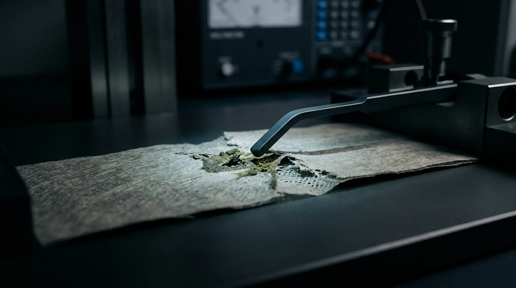
Wear, mechanical misalignment, and electrolyte vapor deposit formation on probe tips degrade sensing repeatability over extended factory operating shifts. Piston spring fatigue weakens contact force, creating intermittent drive current interruptions or sense line noise during indexing cycles. Automated line monitors evaluate contact resistance between drive and sense paths before each measurement stroke to confirm fixture integrity.
Quality engineers enforce strict probe replacement intervals to stop worn contacts from falsely failing acceptable cell batches. Sourcing contracts mandate four-wire test verification protocols across all factory acceptance documentation. Automated manufacturing yields collapse when probe maintenance routines fail.