Four Wire Kelvin Sensing Principles in Low Impedance Battery Testing
Four-wire Kelvin sensing isolates drive current from potential sensing, eliminating lead and contact resistance errors in sub-milliohm battery impedance tests.
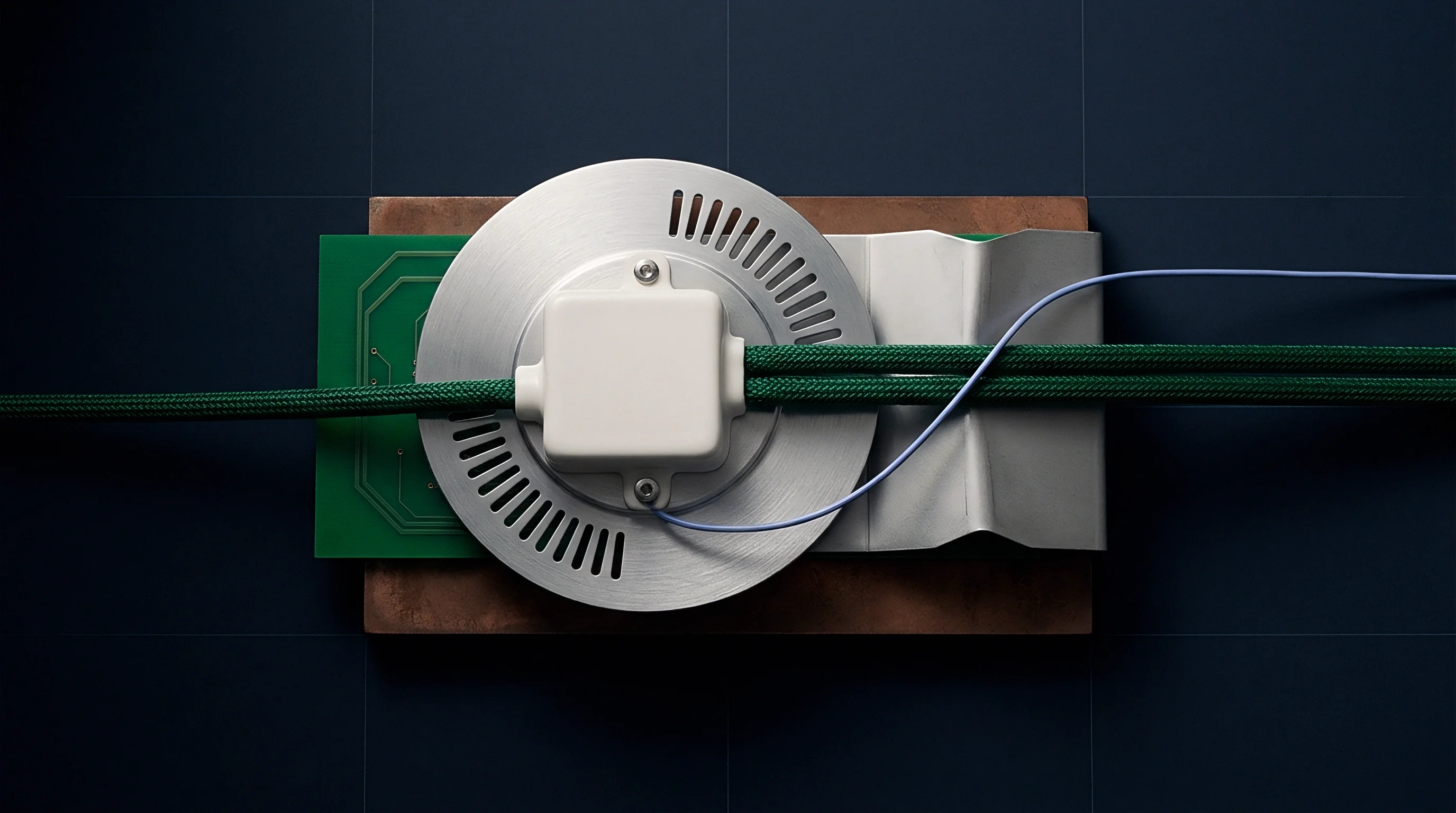

Circuit
Modern prismatic and large cylindrical lithium-ion cells present internal resistance values well below one milliohm. A typical 280 Ah lithium iron phosphate cell exhibits an AC internal resistance between 0.15 and 0.25 milliohms at one kilohertz, while a high-nickel 21700 cylindrical cell registers between 10 and 15 milliohms. At these levels, two-point methods measure the cell alongside the test leads and contact interfaces rather than the cell alone.
Standard copper leads add five to fifty milliohms of series resistance, and the contact junction between probe and terminal contributes another one to ten milliohms depending on clamping pressure, surface oxidation, and plating material. On a sub-milliohm cell, that pushes measurement error past several hundred percent.
The four-terminal Kelvin configuration isolates lead and contact resistances from the voltage sense path by splitting the interface into two dedicated pairs. The drive pair ~ Force High and Force Low ~ injects a regulated perturbation current through the cell, while Sense High and Sense Low connect across the terminals to monitor the resulting drop. Because the voltage instrument’s input impedance typically exceeds ten megohms, current drawn through the sense lines stays negligible, routinely below one nanoampere.
Under a 10 A excitation current on a 0.2 mΩ prismatic cell, a 5 mΩ sense lead resistance induces an error under 0.001 percent when paired with a 10 MΩ input stage.
Current delivery and potential detection remain physically decoupled to protect measurement integrity. Lead wiring, fixture switches, and terminal interfaces all impose ohmic losses on the drive path, altering the compliance voltage required from the source instrument without changing the potential across the battery. The sense lines pick up only the potential drop generated across the active electrochemical system between the probe contact tips.

Drive and Sense Path Separation Mechanics
Measurement errors develop if force and sense conductors touch before reaching the terminal face. Joining them inside the fixture block places the block-to-terminal contact resistance directly inside the voltage sensing loop, collapsing the four-wire setup into a two-wire interface at the boundary. True Kelvin sensing requires isolated conductor paths straight to the point where mechanical probe tips meet the terminal surface.
Current spreading within the terminal material sets up localized potential gradients. On large prismatic cells with solid aluminum or copper terminals, current injected by a single probe tip spreads laterally through the metal before reaching the internal jelly roll or electrode stack. Placing the sense probe outside that primary path registers an artificial voltage drop caused by bulk metal resistivity rather than internal cell kinetics.
Getting an accurate impedance measurement requires centering the sense contact on the terminal axis and placing the force contact symmetrically around it.
Any leakage between the force and sense circuits degrades instrument sensitivity. Mechanical wear, debris, and moisture create high-impedance parallel bridges across isolated terminals. Preserving physical separation between drive lines and measurement paths ensures cable losses never enter the recorded impedance.


Pin
Mechanical probe tips form the physical interface between an automated test bench and the cell. That interface is an active mechanical junction governed by surface roughness, elastic deformation, and tarnishing. Fresh aluminum terminals develop an insulating oxide layer within minutes of exposure to air, creating enough electrical resistance to skew readings under light contact loads.
Kelvin pins overcome this passivating layer by applying sufficient mechanical force to pierce or wipe through the surface.
Spring-loaded pogo pins maintain consistent contact pressure across production runs. Fixtures generally use one of two layouts: paired independent pins seated side by side, or coaxial Kelvin pins with a center sense needle isolated from an outer force crown by an internal sleeve. Coaxial designs ensure concentric geometry, locking in the spatial relationship between current injection and voltage sensing.
Twin pins permit wider spacing, lowering capacitive coupling between leads while claiming more terminal area.
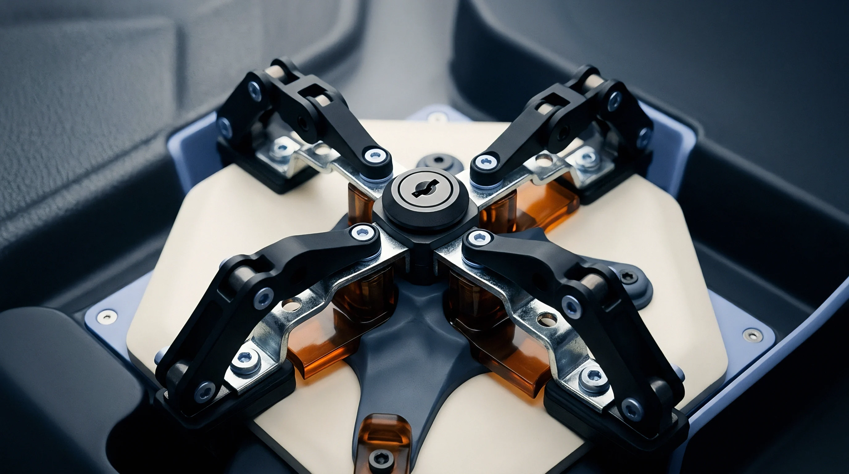
How Does Tip Geometry Dictate Contact Reliability?
Probe tip geometry governs how spring force translates into contact pressure. Sharp spear tips focus the load onto an area of a few square micrometers, generating pressures high enough to exceed the terminal metal’s yield strength, fracture surface oxides, and establish microscopic metal-to-metal junctions. While spear tips perform well on hardened nickel, they pit soft aluminum.
Crown and serrated tips spread the load across multiple raised edges instead, cutting through surface layers at several points with less penetration depth.
| Tip Configuration | Typical Contact Radius (mm) | Apparent Contact Area (mm²) | Initial Contact Resistance (mΩ) | Terminal Indentation Depth (µm) |
|---|---|---|---|---|
| Single Spear (60°) | 0.08 | 0.02 | 0.45 to 0.85 | 12 to 18 |
| Four-Point Crown | 0.45 | 0.15 | 1.20 to 2.10 | 4 to 7 |
| Serrated Edge (8-Tooth) | 0.60 | 0.28 | 1.80 to 3.40 | 2 to 4 |
| Chisel Blade | 0.30 | 0.09 | 0.80 to 1.50 | 6 to 10 |
Tip plating determines operating life. Beryllium copper plated with hard gold serves as the standard for low-current testing, offering high electrical conductivity and resisting oxidation in ambient air. However, high-volume production lines that repeatedly strike abrasive aluminum oxide can strip soft gold within weeks.
Industrial systems substitute rhodium or hardened electroless nickel-phosphorus. Rhodium holds up against abrasion, preserves tip geometry over tens of thousands of cycles, and prevents terminal metal from welding to the probe during high-current DC pulses.
Microscopic terminal oxidation creates variable contact resistances that swamp unshielded measurement fixtures.
Debris accumulation is a constant problem during incoming cell inspection. Aluminum and nickel fines scraped from terminals settle between the inner needle and outer sleeve of coaxial pins. This buildup binds the assembly, cutting effective contact force, and can bridge the Force and Sense lines inside the probe body.
- Mechanical binding restricts the inner probe stroke, preventing the sense pin from reaching the terminal plane when surface height varies.
- Internal bridging creates a resistive connection between force and sense paths inside the coaxial barrel, injecting a portion of the drive current into the measurement stage.
- Tip blunting increases the apparent contact area, dropping localized contact pressure below the threshold required to fracture surface passivation layers.
- Terminal galling transfers soft aluminum onto the probe face, altering probe work function and increasing thermal electromotive force generation.
Unchecked probe wear leads to apparent drift in cell impedance, driving false sorting rejections and distorting warranty tracking in automated grading lines.


Loop
Alternating current impedance measurements introduce inductive effects absent in direct current testing. Standard cell screening relies on AC internal resistance at exactly one kilohertz. At that frequency, the fluctuating drive current sets up an oscillating magnetic field around the test leads.
When this flux links the voltage sensing loop, Faraday induction generates an extraneous voltage across the measurement circuit.
This induced error scales directly with the mutual inductance between drive and sense paths, which depends on the loop area enclosed by the sense lines and their distance from the force conductors. Because the induced voltage leads excitation current by ninety degrees, it reads as inductive reactance. On high-capacity cells with impedances below 0.3 milliohms, an open fixture loop spanning just five square centimeters can generate an inductive error larger than the battery’s actual ohmic resistance.
When Do Induced Mutual Voltages Corrupt Readings?
Electromagnetic pickup causes substantial measurement error when sense leads run parallel to drive lines without cancellation. Drive cable flux cuts across the gap between positive and negative sense leads, forcing the meter to read the vector sum of the electrochemical impedance and the induced voltage. At one kilohertz, this shifts the measured phase angle toward inductive behavior, masking the real charge transfer resistance and displacing the high-frequency ohmic intercept on a Nyquist plot.
Controlling mutual inductance comes down to closing loop area in the sensing harness. Twisting Sense High and Sense Low leads together forces adjacent half-twists to capture opposing fluxes, cancelling net pickup. Twisting Force High and Force Low cables similarly curtails the radiated field.
Coaxial lines suppress coupling further because return currents run concentrically around the center conductor, containing the external field.
A physical loop area of 2 cm² between unshielded sense leads introduces over 12 µΩ of false inductive reactance at 1 kHz AC-IR.
Fixture wiring requires a disciplined layout during assembly:
- Route drive conductors through braided coaxial cables up to the terminal clamp assembly to retain complete field containment.
- Twist sense leads together at a pitch of at least fifteen turns per meter until the wires reach the base of the Kelvin probe holder.
- Position the sense wiring ninety degrees relative to the primary drive conductors where leads cross, suppressing mutual field coupling.
- Enclose the probe mounting assembly in an aluminum or mu-metal enclosure to shield the contact interface from external inverter noise.
- Terminate outer cable shields to instrumentation analog ground at a single node to prevent ground loop circulating currents.
Skin depth effects alter current paths through fixture conductors as frequency climbs. At one kilohertz, copper has a skin depth of roughly two millimeters, which does not limit bulk conduction in standard wire gauges. Solid busbars and terminal clamps, however, experience edge crowding that shifts the physical origin of the field relative to the sense probes.
The unresolved issue is whether automated sorters can dynamically correct for geometry-dependent mutual inductance across varying cell lots without frequent manual zeroing.


Perturbation
Characterizing low-impedance cells requires matching the electrical excitation profile to the target electrochemical process. Industrial testing relies primarily on two methods: single-frequency AC perturbation (1 kHz AC-IR) and multi-stage DC current steps (DC-IR). These techniques interrogate entirely different mechanisms within the cell.
The 1 kHz AC measurement isolates the cell’s ohmic resistance, capturing electronic resistance through current collectors, tabs, coatings, and terminals, along with ionic resistance through electrolyte-filled separator pores. At one kilohertz, double-layer capacitance across the interface effectively shorts the charge transfer resistance, leaving a voltage response proportional to bulk transport, provided high currents do not alter cell temperature.
Direct current testing engages deeper kinetic processes. A constant current pulse applied for one hundred milliseconds to thirty seconds drives ion transport across the interface, initiating charge transfer and solid-state diffusion within the host lattices. The recorded potential shift shows a composite response: an immediate ohmic drop, an exponential rise from activation polarization, and a linear diffusion ramp.
Evaluating these curves requires tracking current amplitude and pulse length together.

Excitation Current Selection Mechanics
Choosing perturbation amplitude balances signal-to-noise ratio against thermal disturbance. On a 300 Ah storage cell with 0.18 milliohms of internal resistance, a 100 milliampere signal produces just eighteen microvolts across the terminals. That approaches the thermal noise floor of factory instruments and risks interference from ambient noise.
Raising the test current to ten amperes produces a 1.8 millivolt drop, giving analog-to-digital converters a clean signal to process.
Excessive current causes localized Joule heating in the cell core and at probe junctions. Dissipating power across internal resistance heats the cell, lowering electrolyte viscosity, accelerating ion transport, and artificially reducing measured internal resistance over longer test sequences.
| Standard / Method | Signal Type | Perturbation Amplitude | Duration / Frequency | Dominant Kinetic Regime |
|---|---|---|---|---|
| IEC 61960-3 (AC-IR) | Sinusoidal AC | 10 mA to 100 mA RMS | 1.0 kHz ± 10% | Pure Ohmic (Electronic + Ionic) |
| IEC 61960-3 (DC-IR) | Current Step | 0.2C discharge to 1.0C pulse | 100 ms and 10 s steps | Ohmic + Charge Transfer + Diffusion |
| VDA Performance Test | Current Step | Dynamic high-pulse (up to 5C) | 2 s, 10 s, 30 s pulses | Mixed Kinetic + Concentration Overpotential |
| ISO 12405-4 | Pulse Train | Power-scaled discharge steps | 1 s to 10 s discharge | Thermal + Electrochemical Polarization |
Establishing clear test parameters prevents misleading classification during incoming cell inspection:
- Current amplitude limits keep cell temperature rise below 0.1 degrees Celsius over the duration of the measurement sweep.
- Sampling frequency rates capture the initial ohmic drop within five milliseconds of pulse onset to isolate electronic resistance from electrochemical activation.
- State of charge boundaries restrict testing to between 40% and 60% capacity where open-circuit voltage curves exhibit minimal slope.
- Rest duration controls enforce a minimum twenty-minute thermal and chemical relaxation period following any prior cycling.
Ohmic resistance yields immediate voltage response whereas electrochemical transfer exhibits distinct time-dependent delay.
Supply agreements governed by IEC 61960-3 mandate that internal resistance values explicitly cite the exact measurement method, frequency, and sample temperature, precluding suppliers from substituting 1 kHz AC-IR data for DC resistance requirements.

Drift
Temperature differentials across test fixtures produce DC measurement offsets via the Seebeck effect. When dissimilar metals meet across a thermal gradient, a thermoelectric voltage develops across the interface. Battery test benches route copper sense lines through brass probe barrels, nickel-plated springs, rhodium tips, and aluminum or copper cell terminals.
These junctions generate thermal EMFs ranging from a few microvolts to tens of microvolts per degree Celsius.
Automated production environments sustain noticeable local temperature gradients. Drive current through resistive contact points warms the probe tips, while ambient air or chilled pneumatic clamps cool the fixture body above. A five-degree gradient across a copper-aluminum junction creates a thermoelectric potential that adds directly to the sensed terminal voltage.
In DC pulse routines, this offset shows up as an artificial difference between measured charge and discharge resistances.
Thermal Dissimilarity and Offset Cancellation
Offset compensation routines mitigate thermoelectric drift during DC measurements. The test instrument records open-circuit voltage immediately before applying the current step, then subtracts that initial offset from the loaded reading. Switched DC testing refines this by running consecutive positive and negative pulses.
Inverting the current flips the sign of the ohmic drop while the thermoelectric offset polarity stays constant, allowing simple algebraic cancellation of the thermal error term.
Precision test channels track four-wire open-circuit voltage continuously to confirm contact stability before pulsing. Watching for voltage settling shows whether mechanical probes have completed initial plastic deformation and mechanical seating. Starting a measurement while contact force is still shifting picks up transient contact resistance decay from probe creep rather than true cell behavior.
Calibrating sub-milliohm benches calls for traceable reference shunts made from low-temperature-coefficient alloys. Manganin and Evanohm standards keep temperature coefficients below five parts per million per degree Celsius, holding stable resistance baselines down to fifty microohms. These solid metal artifacts require dedicated four-terminal geometries with precisely machined voltage taps to keep current distribution from skewing the reference value.
Routine verification maintains fixture integrity across production shifts. Automated handlers cycle Kelvin probes against gold-plated copper calibration coupons every five hundred operations. Rises in interface resistance, shifts in open-loop inductance, or imbalances between dual probes flag automated pin replacement or trigger pneumatic cleaning routines.
Skipping regular contact verification allows undetected probe wear to skew yield data across the fixture’s operating life.