Interfacial Metallic Plating Dynamics under Cryogenic Fast Charging Conditions
Cryogenic fast charging forces graphite anode overpotentials below zero volts, driving metallic lithium deposition that requires pre-heating or dynamic current scaling to prevent cell failure.

Kinetics

Sub-Zero Overpotential Shift and Plating Thresholds
Low-temperature environments force severe electrochemical penalties on lithium-ion cells during high-rate current injection. At temperatures below zero degrees Celsius, the thermodynamic equilibrium between lithium intercalation into graphite hosts and metallic lithium deposition shifts toward active metal precipitation. Cold shifts kinetic equilibrium.
The cell potential drops below zero volts against the lithium-metal reference frame (Li/Li⁺) when total cell polarization exceeds the equilibrium margin of graphite intercalation, which sits between fifty and two hundred millivolts depending on the state of charge.
Charge transfer resistance increases exponentially as temperature falls following Arrhenius behavior. The activation energy barrier for interfacial ion transport across the solid electrolyte interphase ranges from forty to sixty-five kilojoules per mole depending on electrolyte composition and interfacial salt species. When high charging currents pass through this high-resistance interface, the localized overpotential pushes the negative electrode operating potential below the thermodynamic threshold of zero volts versus Li/Li⁺.
Lithium ions deposit as metal.
Plating occurs whenever the localized overpotential at the particle surface drives the graphite anode potential below zero millivolts against the metallic lithium reference pair.
The total overpotential contains three distinct terms operating in series: ohmic polarization across the bulk electrolyte and separator, charge-transfer polarization at the particle boundary, and concentration polarization within the solid graphite matrix. At ambient temperatures around twenty-five degrees Celsius, concentration polarization dominates at high charge rates. At minus twenty degrees Celsius, charge-transfer resistance increases by a factor of fifteen to thirty, becoming the primary governor of cell potential dynamics.

Thermodynamic Driving Forces for Deposition
Thermodynamic forces mandate that metallic lithium plating and graphite intercalation proceed as competing parallel electrochemical reactions. The exchange current density for metallic lithium nucleation remains measurable at cryogenic temperatures, whereas the exchange current density for intercalation drops dramatically. Consequently, when the interfacial overpotential turns negative, metallic deposition becomes kinetically favored over solid-state insertion into the graphite lattice layer.
Solid-state diffusion coefficients for lithium inside graphite particles fall from ten to the power of minus nine square centimeters per second at room temperature down to ten to the power of minus twelve or minus thirteen square centimeters per second at minus thirty degrees Celsius. Ion accumulation at the particle surface creates a steep concentration gradient across the outer shell of the graphite crystal. This surface saturation prevents incoming ions from entering the host structure, leaving surface deposition as the only available path for incoming electric current.
The boundary condition defining the onset of dynamic plating depends directly on particle radius, mass loading, electrode porosity, and temperature. Higher mass loadings increase local current density within electrode pores, accelerating the drop toward zero volts versus Li/Li⁺. Whether small nano-scale metallic nuclei re-intercalate back into the graphite matrix during resting phases at minus twenty degrees Celsius remains an open question under continuous fast-charge conditions.

Chill

Desolvation Energy Barriers at the Anode Interface
Extreme environmental cold alters the fundamental fluid mechanics and solvation structures inside the liquid electrolyte. Lithium ions move through the bulk liquid enclosed within a tight primary solvation shell formed by organic carbonate molecules such as ethylene carbonate, ethyl methyl carbonate, and dimethyl carbonate. Desolvation limits charge transfer rates.
Stripping these tightly bound solvent molecules from the cation prior to interfacial transfer requires substantial thermal excitation energy.
At minus twenty degrees Celsius, bulk electrolyte viscosity increases while liquid ionic conductivity drops from ten millisiemens per centimeter down to less than one millisiemens per centimeter. The desolvation process demands the highest energy contribution along the entire charge transfer path. When high charging rates are applied to frozen cells, desolvation bottlenecks create extreme charge accumulation right outside the solid electrolyte layer, generating intense electric field gradients across the liquid-solid boundary.
Dendrites bridge anode separator gaps. Metallic deposits formed under high desolvation barriers adopt mossy or dendritic microstructures rather than smooth planar films. These irregular metallic structures penetrate the polymeric separator matrix, inducing soft micro-shorts that elevate self-discharge rates and threaten thermal safety.

Mossy and Whiskered Morphological Evolution
Microstructural evolution during cryogenic charging converts active lithium into isolated, electrochemically dead metallic fragments. Dendritic structures feature high surface area ratios, triggering immediate secondary reactions with ambient organic solvent molecules. These parasitic reactions consume active lithium ions and liquid electrolyte solvents, forming thick, inhomogeneous passive surface films.
| Temperature (°C) | Ionic Conductivity (mS/cm) | Diffusion Coeff (cm²/s) | Overpotential Shift (mV) | Plating Onset C-Rate |
|---|---|---|---|---|
| 25 | 10.5 | 1.2 × 10⁻⁹ | 15 | 3.0C |
| 0 | 4.2 | 2.8 × 10⁻¹⁰ | 85 | 1.2C |
| -10 | 2.1 | 6.5 × 10⁻¹¹ | 190 | 0.5C |
| -20 | 0.8 | 1.1 × 10⁻¹² | 340 | 0.15C |
| -30 | 0.2 | 8.0 × 10⁻¹⁴ | 520 | 0.04C |
The morphology of plated lithium varies between mossy structures at moderate overpotentials and sharp needle-like whiskers at extreme negative overpotentials. Mossy lithium consists of porous, interconnected metallic branches with diameters between one hundred and five hundred nanometers. Whiskered lithium forms single-crystal filaments that grow from the root, driving directly into separator pores under localized stress gradients.
Dead lithium accumulation degrades usable cell capacity permanently while increasing internal direct-current resistance. Cells subjected to unmitigated fast charging at minus twenty degrees Celsius lose up to thirty percent of operational capacity within fifty cycles due to active material isolation and electrolyte depletion. Operating cells under unmitigated low-temperature fast-charge profiles leads directly to accelerated capacity loss, high internal resistance growth, and potential internal short-circuit failures.

Detection
Which Non-Destructive Method Identifies Sub-Surface Plating Early?
Identifying metallic deposition inside sealed pouch or prismatic cells requires indirect physical and electrochemical measurements. High-precision coulombic efficiency measurement provides an early signal during laboratory cycling. A sudden drop in coulombic efficiency during cold charging indicates active lithium consumption in non-reversible metallic deposition and secondary film growth.
Differential capacity analysis calculated from low-rate discharge curves reveals structural changes in the graphite intercalation stages. Plated lithium that remains electrochemically active re-intercalates into graphite or dissolves back into the electrolyte during resting or early discharge phases. Voltage relaxation signals metal stripping.
This chemical dissolution process produces a distinct voltage plateau during the relaxation phase immediately following charge termination.
Voltage relaxation analysis identifies metallic lithium stripping through a characteristic voltage plateau during the post-charge rest period.
Non-destructive diagnostic procedures follow a strict analytical sequence to verify whether metallic plating occurred during a fast-charge event:
- Charge the target cell under controlled sub-zero thermal chamber conditions at the specified test C-rate until reaching target state of charge.
- Isolate the cell electrically and record open-circuit voltage relaxation data at a minimum sampling rate of ten hertz for two hours.
- Calculate the time derivative of open-circuit voltage with respect to time to identify the inflection point corresponding to lithium phase dissolution.
- Execute a low-rate C/20 discharge back to baseline voltage while collecting high-precision differential capacity trends.
- Compare the discharge capacity of the stripping plateau against the total charging ampere-hours to quantify reversible plating percentages.

Voltage Relaxation and Stripping Plateau Quantification
The length of the voltage relaxation plateau correlates directly with the mass of electrochemically reversible plated lithium. Coulombs match returned charge totals. When the voltage relaxation curve exhibits a flat slope near zero volts relative to the baseline intercalation potential, metallic lithium exists on the particle surfaces.
Once all metallic lithium dissolves or re-intercalates, the cell potential transitions back to the standard open-circuit potential of intercalated graphite.
Electrochemical impedance spectroscopy captured at sub-zero temperatures provides secondary verification. The high-frequency arc corresponds to ionic transport through passive surface layers, while the mid-frequency arc tracks charge-transfer resistance. The growth of a secondary mid-frequency arc during cycling signals the presence of non-uniform metallic film coverage and damaged interfacial layers.
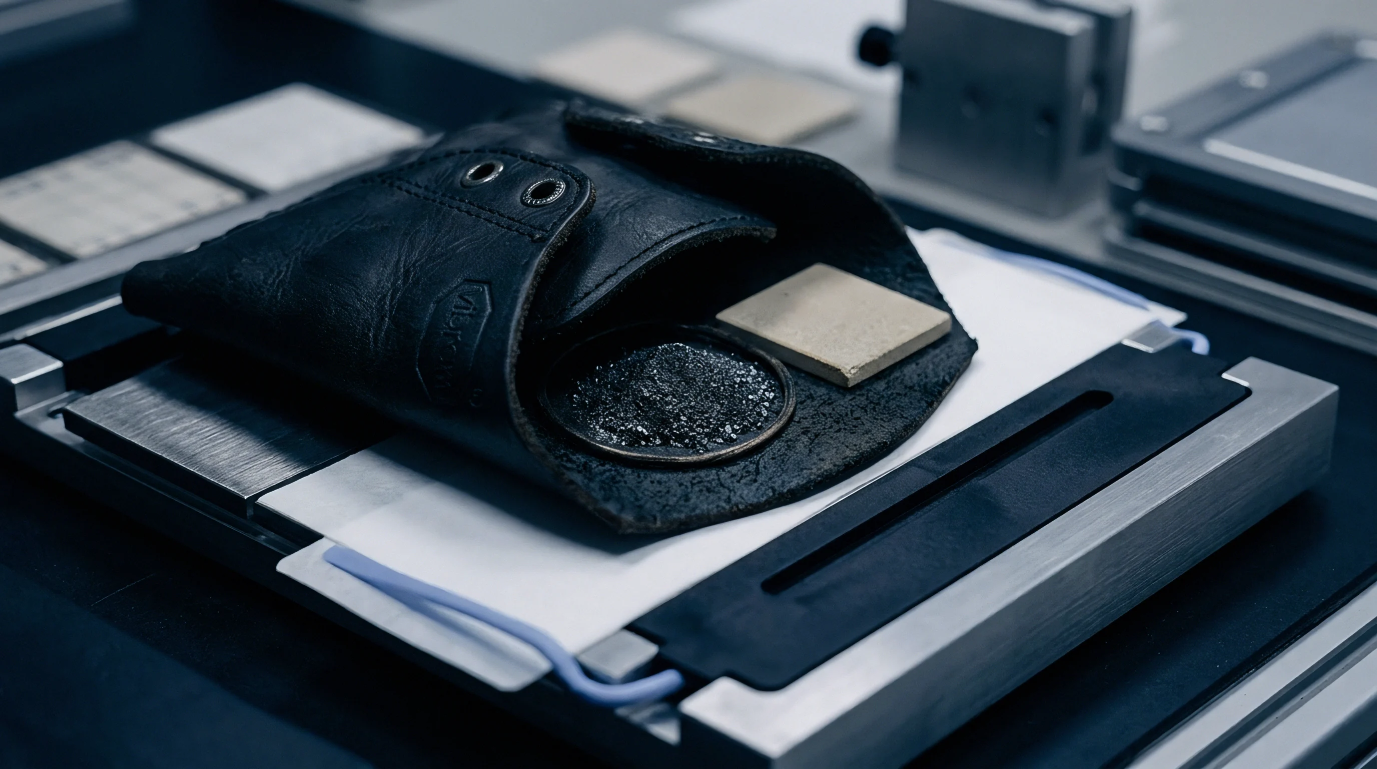
Cell manufacturers frequently state that observed capacity loss under cold conditions stems entirely from temporary electrolyte transport limitations rather than permanent metallic deposition. Laboratory tear-downs and post-mortem scanning electron microscopy of harvested anodes consistently disprove this claim by revealing extensive dead lithium matrices and cracked separator surfaces.

Interphase
Fluorinated Solvents and Low-Viscosity Solvent Blends
Engineering the electrolyte formulation alters the chemical composition and ionic conductivity of the interfacial passivation film. Standard carbonate solvents like ethylene carbonate exhibit high melting points (thirty-six degrees Celsius) and high desolvation energy barriers, making them unsuited for sub-zero operation. Replacing standard formulations with low-melting-point ester co-solvents such as ethyl acetate, methyl propionate, or fluorinated carbonates lowers viscosity and depresses the freezing point of the mixture below minus forty degrees Celsius.
Fluorinated solvents modify the inorganic salt distribution within the solid electrolyte interphase. Formulations incorporating fluoroethylene carbonate or difluoroethylene carbonate promote the formation of a lithium-fluoride-rich interfacial film. Lithium fluoride possesses a wide bandgap, high mechanical strength, and low surface diffusion barriers for lithium ions, suppressing dendritic nucleation at low temperatures.
Incorporating low-viscosity ester co-solvents lowers bulk electrolyte freezing points below minus forty degrees Celsius while reducing ionic transfer resistance.
| Solvent System | Salt Mix (1.2M) | Additive (wt%) | Conductivity (-20°C) | Interfacial R (Ω·cm²) |
|---|---|---|---|---|
| EC/EMC (3:7) | LiPF6 | None | 0.8 mS/cm | 450 |
| EC/EMC/EA (2:5:3) | LiPF6 | 2% FEC | 2.4 mS/cm | 120 |
| FEC/FEMC/EA (1:4:5) | LiFSI | 1% LiDFOB | 4.1 mS/cm | 38 |
| EP/EMC/FEC (4:5:1) | LiFSI / LiPF6 | 0.5% VC | 3.2 mS/cm | 62 |
Lithium bis(fluorosulfonyl)imide salt offers superior ionic conductivity compared to standard lithium hexafluorophosphate at sub-zero temperatures. The FSI anion exhibits a smaller hydrodynamic radius and weaker binding energy with lithium cations, accelerating the desolvation sequence at the interface. Electrolytes combining lithium bis(fluorosulfonyl)imide with fluorinated ester solvents maintain ionic conductivities above three millisiemens per centimeter at minus twenty degrees Celsius.

Anode Microstructure and Surface Modification
Modifying the structural morphology of the negative electrode complements fluid chemical engineering. Standard spherical natural graphite particles suffer from long diffusion pathways and anisotropic ion entry points along basal planes. Edge-plane exposure through physical surface etching increases active insertion sites, spreading localized current over a wider interfacial surface area.
Electrolytes determine interfacial impedance curves. Blending hard carbon or silicon nanoparticles into graphite negative electrodes changes sub-zero kinetic behavior:
- Silicon Nanoparticle Blending expands localized volumetric capacity while offering non-crystallographic insertion pathways that reduce overpotential drops during high C-rate bursts.
- Hard Carbon Coating creates an amorphous surface layer with isotropic ion diffusion channels, lowering interfacial charge-transfer resistance by a factor of three.
- Pore Tortuosity Reduction achieved through magnetic orientation of graphite flakes creates vertical ion pathways, minimizing concentration gradients across electrode thickness.
- Artificial Fluorinated Coatings deposited via atomic layer deposition shield the active material from direct solvent contact, eliminating parasitic liquid consumption.
Low tortuosity electrodes combined with fluorine-rich interfacial films enable stable low-temperature current acceptance. High tortuosity structures concentrate current at the separator-anode boundary, driving immediate surface plating regardless of solvent quality.

Protocol

Multi-Stage Current Maps and Closed-Loop Feedback
Charging control strategy forms the final operational defense against metallic deposition in cold environments. Conventional constant-current constant-voltage charging maps fail at low temperatures because fixed current steps ignore shifting overpotential limits. Adaptive algorithms adjust current magnitude dynamically based on real-time cell voltage, temperature, and estimated surface concentration profiles.
Multi-stage current charging divides the charging window into discrete step-down intervals. As state of charge increases and graphite intercalation potentials approach the plating threshold, current levels step down to allow localized concentration gradients to relax. Heat clears interfacial impedance bottlenecks.
Reference electrodes integrated into commercial test cells enable direct three-electrode monitoring of negative electrode potential. In production battery management systems lacking reference electrodes, physics-based reduced-order electrochemical models estimate the real-time anode potential. When the estimated surface potential approaches five millivolts versus Li/Li⁺, the management system reduces charge current to prevent potential inversion.

Pre-Heating Mechanisms Prior to High-Rate Injection
Internal electro-thermal heating provides rapid cell conditioning prior to fast-charge acceptance. External heating blankets suffer from slow heat conduction through thermal insulation layers, creating large core-to-surface temperature gradients. High-frequency alternating current excitation generates uniform internal Joule heating without driving net electrochemical reactions or lithium deposition.
An integrated thermal management calculation illustrates the advantage of high-frequency self-heating prior to charge injection. Take a fifty kilowatt-hour battery pack resting at minus twenty degrees Celsius. Direct charging at a constant 1C rate (fifty kilowatts) without pre-heating induces immediate surface lithium plating within ninety seconds due to a calculated negative anode potential of minus sixty millivolts.
Applying a twenty-kilohertz alternating current signal at one hundred amperes generates internal sinusoidal resistive heating across the ohmic impedance of the cell. Assuming a bulk internal resistance of sixty milliohms at minus twenty degrees Celsius, internal thermal dissipation power reaches six hundred watts per cell. The pack temperature rises from minus twenty degrees Celsius to plus five degrees Celsius in eight minutes, consuming 0.8 kilowatt-hours of auxiliary energy.
Once the core temperature reaches five degrees Celsius, charge-transfer resistance drops from four hundred and fifty ohms to forty-five ohms square centimeters. The cell then accepts a continuous 2C fast charge (one hundred kilowatts) while maintaining a positive anode surface potential of plus twenty-five millivolts versus Li/Li⁺. Net charging time to eighty percent state of charge drops from one hundred and forty minutes under low-rate step maps down to twenty-eight minutes including the pre-heating cycle.
Contractual supply specifications must incorporate temperature-dependent current limits that automatically inhibit fast-charge profiles below zero degrees Celsius unless active self-heating mechanisms pre-condition the core cell temperature above five degrees Celsius.

Warranty

Commercial Allocation of Cold-Climate Degradation Risk
Commercial cell supply agreements frequently obscure degradation liability arising from low-temperature fast charging. Standard cycle-life performance guarantees cite test conditions executed precisely at twenty-five degrees Celsius. Operating cells outside specified thermal windows voids standard cycle-life warranties unless explicit low-temperature addenda exist within the commercial contract terms.
Cell buyers serving cold-climate markets negotiate specialized warranty clauses defining permissible charge rates across defined temperature bands. Cell manufacturers utilize integrated battery management system logs to track historical charging events executed below freezing points. Warranty claims involving capacity loss or internal micro-shorts face rejection if operational logs record current injection exceeding specified plating boundary limits.
| Operating Mode | Primary Failure Mode | Warranty Status | Landed Cost Impact (%/yr) | Field Return Rate (%) |
|---|---|---|---|---|
| Unheated Fast Charge (<-10°C) | Metallic Plating / Shorts | Voided Immediately | +35% (Early Replacement) | 4.8% |
| Step-Down Current Mapping | Gradual SEI Thickening | Conditional Coverage | +12% (Capacity Loss) | 1.1% |
| AC Pulse Pre-Heating | Minor Thermal Stress | Full Coverage | +3% (Energy Overhead) | 0.2% |
| Thermal Blanket Pre-Heating | Surface Film Aging | Full Coverage | +5% (Time Delay Cost) | 0.4% |
Warranty terms allocate degradation risks. Freight forwarders and pack integrators verify thermal management validation data during second-source supplier qualifications to align commercial guarantees with real-world climate exposures.
Landed-Cost Dynamics over Extreme Temperature Lifecycles
Landed cell cost calculations must incorporate the financial impact of low-temperature degradation rates. A cell possessing a low purchase price per kilowatt-hour becomes commercially expensive if sub-zero plating shortens usable operational life from ten years down to three years. Warranty reserves for cold-climate battery systems routinely run two to four times higher than reserves set for stationary systems operating in climate-controlled enclosures.
Standard qualification protocols under international standards such as UN 38.3, IEC 62133, and UL 2580 evaluate safety parameters under extreme temperature conditions, but do not guarantee long-term electrochemical stability under sub-zero fast charging. UN 38.3 testing subjecting cells to thermal shock between minus forty degrees Celsius and plus seventy-five degrees Celsius verifies mechanical structural integrity, yet omits dynamic overpotential checks during low-temperature electrical driving.
Unmitigated plating shortens cell life. Comprehensive sourcing dossiers mandate supplementary non-destructive cycling qualification steps, including differential capacity and voltage relaxation screening at minus twenty degrees Celsius, prior to issuing purchase orders for high-rate cold-climate deployments.