Acoustic Monitoring Thresholds for Sub Critical Micro Crack Propagation in Swollen Separators
Acoustic emission monitoring identifies sub-critical micro-cracking in swollen separators when burst amplitudes exceed thirty-eight decibels between 180 and 320 kHz.


Rupture
Polyolefin separator membranes experience continuous biaxial tensile stresses inside sealed lithium-ion cells as active material particles expand during lithium insertion. Wet-process polyethylene separators coated with ceramic sub-micron particles, such as alpha-alumina or zirconium dioxide, absorb liquid organic carbonate solvents and undergo dimensional swelling up to five percent in thickness while constrained under stack pressure. Mechanical stack pressure applied by pack frames ranges from 0.3 MPa in pristine pouch cell stacks to over 1.5 MPa as anode graphite surfaces accumulate solid electrolyte interphase films.
Compressive forces force solvent-swollen polyolefin fibrils into localized stress concentrations around hard ceramic particulates, driving shear band formation across the micro-porous matrix.
Micro-crack formation within the brittle ceramic top-coat precedes macro-tearing of the underlying polymeric base film. Sub-critical micro-fracturing generates transient elastic stress waves that propagate through the fluid-saturated pore network. These elastic stress waves, known as acoustic emissions, release energy across ultrasonic frequency bands ranging from 50 kHz to 500 kHz.
Detecting sub-critical micro-cracking prior to total dielectric breakdown demands precise acoustic threshold definition, separating crack nucleation events from background operational noise like gas bubble evolution and fluid friction.
Separator thickness growth exceeding three percent under electrolyte immersion lowers the strain required to initiate micro-fractures in ceramic coatings by twenty-four percent.
Swelling alters the acoustic velocity within the porous separator matrix. Fluid displacement inside five-hundred-nanometer pore channels increases acoustic signal attenuation, shifting the dominant waveform frequency toward lower bands. Active sub-critical micro-crack propagation releases strain energy in high-frequency bursts lasting between five and fifty microseconds.
When ceramic particles debond from the polyolefin substrate under shear stress, acoustic emission energy spikes while wave duration remains extremely tight. Micro-crack growth rates below one nanometer per cycle accumulate damage without causing immediate electrical short circuits, creating an invisible degradation pathway that degrades high-voltage safety margins over hundreds of field cycles.
Sustained cycling under high stack pressure forces sub-critical micro-cracks to coalesce into through-thickness tears. High power charging protocols accelerate micro-crack propagation by generating localized thermal gradients across the separator face. Differential thermal expansion between the ceramic coating and the polyethylene substrate increases interfacial shear strain.
Ignoring sub-critical acoustic emissions during initial engineering validation leads to unexpected field failures, as compromised separators suffer catastrophic dielectric punch-through under moderate mechanical shock loads.
Sensor
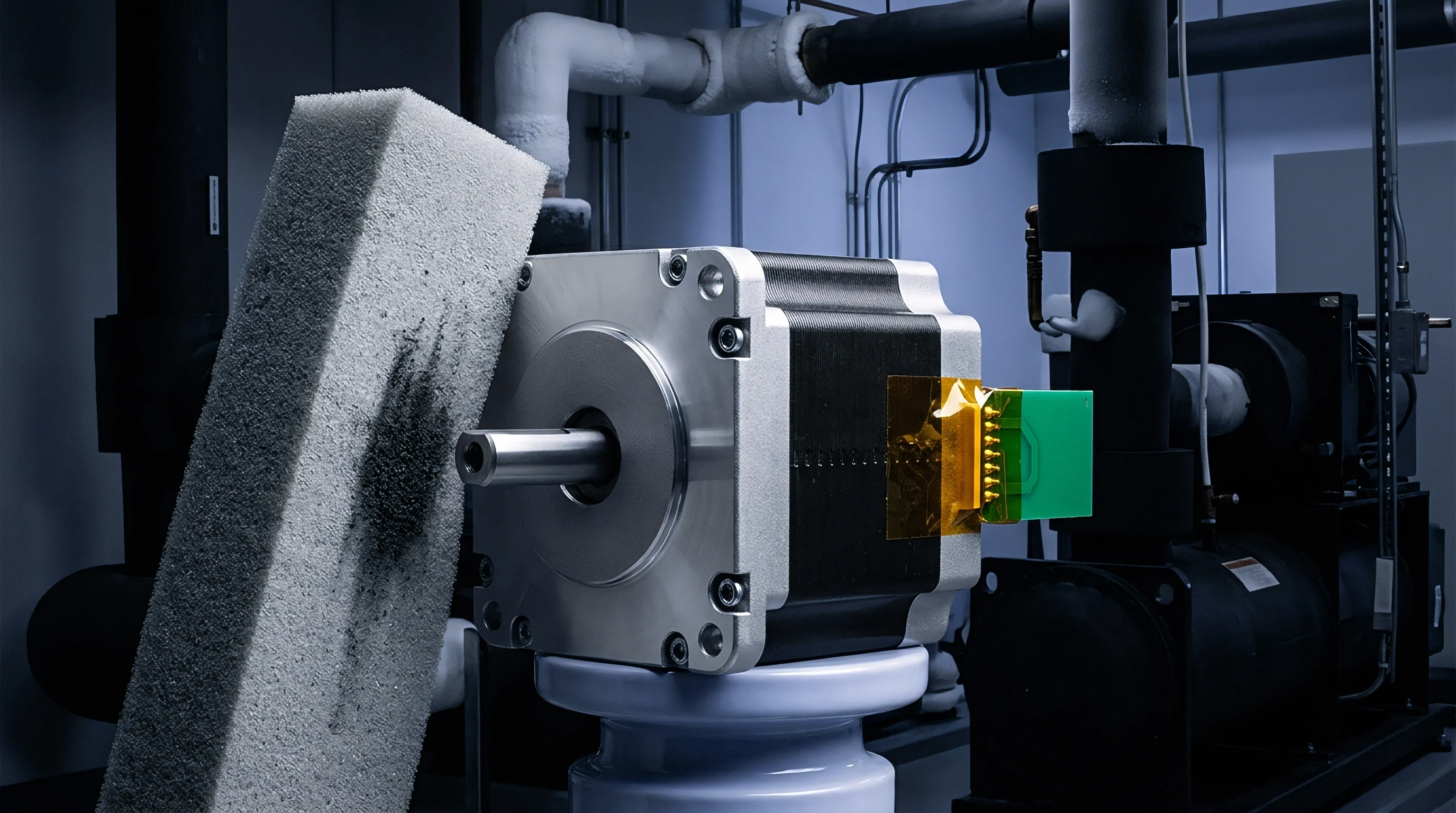
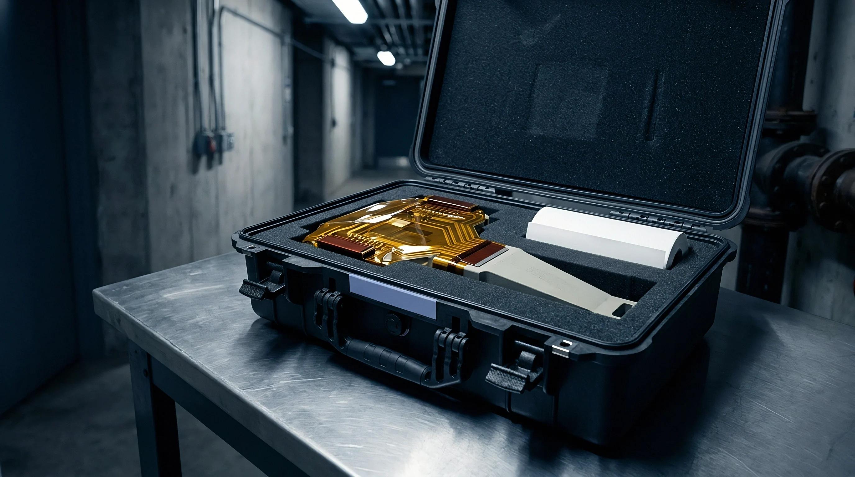
Piezoelectric acoustic transducers placed on external cell surfaces convert structural stress waves into electrical voltage signals. Direct physical coupling between the transducer face and the cell housing governs signal transmission efficiency. Pouch cell formats allow direct acoustic coupling along the wide planar face using silicone-based couplants, whereas prismatic aluminum cases require high-viscosity epoxy bonding or spring-loaded mechanical clamps to overcome casing resonance.
Acoustic wave velocity through aluminum cell walls reaches six thousand meters per second, while velocity inside electrolyte-saturated polyolefin separators drops below twelve hundred meters per second due to viscous fluid drag.

Coupling Transducers across Variable Enclosure Geometries
Transducer selection dictates the sensitivity threshold for sub-critical acoustic event detection. Broad-band piezoelectric sensors operating between 100 kHz and 450 kHz capture full acoustic spectrum signatures, enabling fast Fourier transform spectral decomposition. Differential resonant sensors centered at 150 kHz provide superior signal-to-noise ratios by filtering out low-frequency pack vibration and high-frequency inverter electrical noise.
Internal cell components attenuate acoustic signals at rates dependent on electrolyte saturation and stack compaction.
| Cell Format | Housing Material | Coupling Method | Attenuation Rate (dB/mm) | Optimal Frequency (kHz) |
|---|---|---|---|---|
| Pouch Cell | Aluminum Laminate Film | Silicone Gel Clamp | 1.2 to 1.8 | 150 to 300 |
| Prismatic Cell | 3003 Aluminum Alloy Shell | Epoxy Adhesive Rigid Bond | 0.4 to 0.7 | 100 to 250 |
| Cylindrical 21700 | Nickel-Plated Steel Can | Magnetic Spring Fixture | 0.2 to 0.5 | 200 to 450 |
| Blade Format | Extruded Aluminum Shell | Direct Thermal Couplant | 0.6 to 1.1 | 120 to 280 |
Acoustic signal pathways pass through multiple physical boundaries inside a cell package. Each impedance boundary reflects a portion of the acoustic wave energy, reducing signal amplitude before reaching external measurement equipment. Pouch cell tab areas introduce substantial acoustic reflection, whereas prismatic side walls conduct high-frequency elastic waves with minimal wave dispersion.
- Acoustic impedance mismatch at the separator-electrolyte interface reflects up to thirty percent of micro-crack pulse energy back into the porous core, dampening measurable amplitude at external housing surfaces.
- Couplant thermal degradation during high-rate discharge cycles causes signal attenuation drift exceeding five decibels over two hours, creating false readings during continuous monitoring trials.
- Mechanical frame clamping force variability alters sensor contact pressure, introducing amplitude measurement errors up to eight decibels across multi-cell pack validation arrays.
- Case resonance interference at specific discharge rates masks sub-critical separator micro-crack emission pulses beneath structural vibration noise.
Cell manufacturers frequently attribute observed high-amplitude acoustic emission spikes to internal gas evolution or tab friction rather than acknowledging separator structural degradation during early aging qualification tests.

Threshold
Establishing actionable signal metrics requires isolating micro-crack acoustic signatures from ambient operational background noise. Background mechanical noise generated by fluid flow, thermal expansion creak, and test bench fixtures rarely exceeds thirty-two decibels on the acoustic energy scale. Sub-critical micro-fractures within alpha-alumina separator coatings generate discrete burst-type acoustic signals with peak amplitudes ranging between thirty-eight and fifty-four decibels.
Crack initiation in the underlying polyolefin polymer backbone produces higher amplitude acoustic events ranging from fifty-six to seventy-two decibels.

Is Acoustic Amplitude Predictive of Micro Crack Growth?
Signal duration and count rate metrics differentiate benign structural shifts from destructive micro-crack propagation. Sub-critical ceramic layer fracturing produces brief acoustic bursts with rise times under four microseconds and total duration under twenty microseconds. Polymer fibril tearing exhibits extended signal duration exceeding one hundred microseconds due to sustained stress relaxation across the fracture zone.
Absolute energy calculations integrate the squared voltage envelope over event duration, providing an exact acoustic energy metric measured in attojoules.
| Physical Phenomenon | Amplitude Range (dB AE) | Peak Frequency Range (kHz) | Signal Duration (µs) | Energy Class (attojoules) |
|---|---|---|---|---|
| Electrolyte Gas Bubble Collapse | 25 to 34 | 40 to 80 | 120 to 350 | 1 to 15 |
| Active Material Friction Creep | 30 to 37 | 90 to 140 | 50 to 180 | 10 to 40 |
| Ceramic Coating Micro-Cracking | 38 to 54 | 180 to 320 | 3 to 18 | 80 to 450 |
| Polyolefin Fibril Tensile Tear | 56 to 72 | 300 to 480 | 85 to 240 | 1200 to 8500 |
Calculating the cumulative acoustic energy curve over cycling yields a clear predictive signal for separator structural failure. Consider a fifty-ampere-hour pouch cell operating under one megapascal uniform stack pressure. During initial formation cycling, baseline acoustic energy remains below fifty attojoules per cycle.
As swollen ceramic particles undergo cyclic shear displacement, micro-crack initiation accelerates, generating a steady acoustic emission rate of twelve events per discharge step. A sharp upward inflection in cumulative acoustic energy, where event rates exceed one hundred events per minute with amplitudes above forty-five decibels, marks the transition from stable micro-cracking to macro-scale separator degradation.
Cumulative acoustic energy rates exceeding five thousand attojoules per hour under constant current cycling indicate irreversible separator structural decay.
Quantitative analysis demands digital bandpass filtering between 100 kHz and 400 kHz to eliminate hydraulic pump noise in liquid-cooled pack test rigs. Setting the hardware gain to forty decibels ensures low-energy micro-crack signals cross the digitizer trigger threshold without saturating signal preamplifiers during intense tearing events.
Under standard UN 38.3 vibration test conditions, contract specifications mandate that continuous acoustic monitoring record zero acoustic burst events exceeding forty-eight decibels in the 200 kHz to 350 kHz band to verify separator mechanical integrity.
Rig
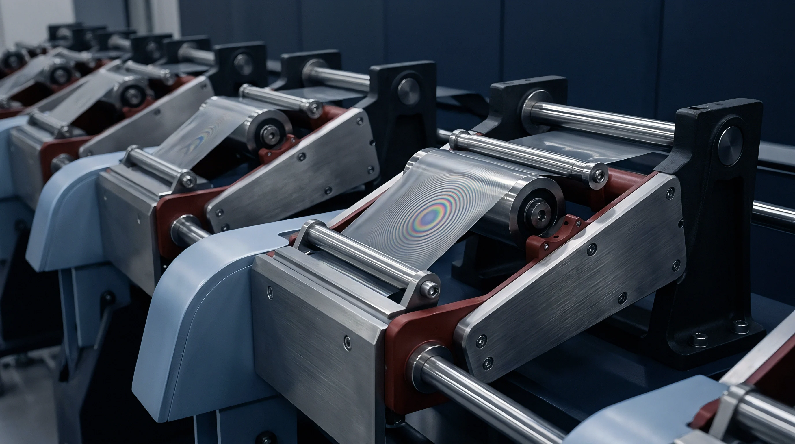
Integrating non-destructive acoustic monitoring into high-throughput NPI pilot production lines mandates specialized test fixtures. Test channels incorporate spring-loaded waveguide pins that make mechanical contact with cell enclosures without breaching moisture barriers or interrupting electrical tab connections. Waveguides manufactured from grade 304 stainless steel transmit high-frequency acoustic waves from tight pack geometries out to externally mounted piezoelectric sensors, protecting sensitive crystal transducers from elevated environmental chamber temperatures.
Automated inline testing requires clean acoustic isolating mounts. Elastomeric dampening pads isolate test cells from factory floor vibration, hydraulic press noise, and conveyor drive motor chatter. Multi-channel signal acquisition hardware samples acoustic waveforms at continuous rates up to ten megasamples per second per channel, capturing full transient pulse detail across every cell in a module formation tray.
- Mount the target cell inside the acoustic isolation fixture, applying exactly 0.5 MPa uniform mechanical constraint using calibrated load cells.
- Apply ultrasonic couplant gel to the designated waveguide contact site on the cell container wall.
- Engage the acoustic waveguide probe spring clamp to establish a constant five-newton contact force.
- Execute an automated pre-test signal check by firing an acoustic pulse generator to verify wave transmission efficiency across the sensor coupling interface.
- Initiate the prescribed fast-charge electrical cycling program while capturing real-time acoustic waveform streams across forty-eight parallel acquisition channels.
- Process incoming voltage streams through real-time field-programmable gate arrays running digital bandpass filters centered at 250 kHz.
- Log peak amplitude, event duration, rise time, and calculated energy values to the central quality control production file.
- Trigger an automated channel reject flag when cumulative event counts exceeding forty-two decibels pass twenty-five pulses per amp-hour of throughput.
High background acoustic noise in industrial assembly environments distorts low-amplitude micro-crack detection. Signal processors isolate actual crack signals using spatial location algorithms based on time-difference-of-arrival calculations across multi-sensor arrays. Sensors mounted on opposite ends of a prismatic cell container locate the origin of acoustic emissions within three millimeters of spatial resolution, pinpointing whether micro-cracking occurs along high-strain cell edges or across central active material areas.
Signal processing blocks convert raw analog voltage time-series into actionable NPI pass-fail data within milliseconds of event detection.
What signal extraction hardware configuration balances inline production line takt times against the high sampling frequencies needed to resolve four-microsecond acoustic rise times?

Boundary
Specifying separator durability requirements in supply agreements requires technical clarity regarding measurable acoustic threshold metrics. Cell engineering teams specify maximum allowable acoustic emission burst counts during preliminary qualification builds to protect downstream pack integrators from premature field degradation. Supply contracts define cell acceptance criteria using explicit acoustic energy limits recorded during standard NPI validation protocol runs.
Responsibility boundaries split cleanly between component suppliers, cell manufacturers, and pack integrators. Separator film manufacturers guarantee base film tensile strength, porosity consistency, and ceramic coating adhesion values under standard laboratory test conditions. Cell manufacturers own the mechanical assembly quality, electrolyte swelling compatibility, and stack pressure distribution within the sealed cell container.
Pack integrators assume responsibility for maintaining pack-level compressive frame loads within design boundaries to prevent excessive localized shear stress on swollen separator matrices.
Legal disputes arising from unexpected field capacity loss or thermal safety events rely on acoustic emission historical logs generated during NPI pilot line formation runs. Documented acoustic energy spikes above defined micro-crack thresholds serve as conclusive evidence of internal separator structural degradation prior to pack assembly. Sourcing practices mandate complete acoustic qualification dossiers before releasing mass production purchase orders for high-energy cell lots.
- Separator reel lot verification files must contain certified tensile strain limits alongside ceramic coating peel-strength test records.
- Cell formation acoustic inspection logs must document continuous acoustic emission event rates across all pre-charge and primary formation cycles.
- Module compression fixture drawings must detail dynamic spring force compensation boundaries designed to limit stack pressure during swelling.
- Field return failure dossier standards require acoustic baseline comparison against initial NPI production line birth certificate signatures.
Clear definition of non-destructive acoustic evaluation parameters establishes undeniable accountability for separator failure modes. Quality teams enforce these threshold limits at every NPI gate, ensuring that compromised cells never advance into production pack integration channels.