Calculating Intermetallic Growth Rates to Set Stamping Tooling Replacement Intervals
Calculating dynamic intermetallic growth rates establishes press stroke limits that prevent tab burrs and optimize die replacement intervals.

Heat
High-speed shear deformation of bimetallic tab stock generates localized energy spikes exceeding three hundred degrees Celsius at the punch edge. Friction creates heat. During continuous press operations running between two hundred and six hundred strokes per minute, this transient thermal rise concentrates directly along the cut interface of copper-aluminum clad foils and nickel-plated copper busbars.
The rapid plastic strain rate induces solid-state diffusion prior to thermal dissipation into the surrounding tool steel. When localized temperatures cross kinetic activation thresholds, elemental diffusion accelerates rapidly across the material boundaries.
This localized energy conversion alters the metallurgical state of the workpiece and the stamping die interface. High strain rates force intimate contact between clean metal matrices by breaking surface oxides. Solid-state atomic migration follows instantly within milliseconds of each stroke.
Over thousands of continuous punch cycles, this thermal accumulation drives phase transformations that yield brittle intermetallic layers on both the workpiece edge and the surface of the stamping punch.

Interface Friction and Intermetallic Phase Formation
Dynamic contacts between clad layers transform sliding mechanical friction into thermal energy along the shear zone. Shear deformation concentrates within a narrow band measuring less than fifty micrometers wide. In copper-aluminum tab materials, friction elevates localized temperatures into the range where intermetallic growth initiates.
The resulting phases include theta-phase copper aluminide and gamma-phase copper aluminide. These compounds exhibit extreme hardness levels that drastically alter tool wear rates.
Base aluminum exhibits a Vickers hardness around eighty, while soft copper registers near one hundred and ten. Intermetallic compounds formed at the shear edge reach hardness values between five hundred and five hundred and fifty HV. This sudden fivefold escalation in localized material hardness transforms a ductile shearing process into an abrasive cutting environment.
Standard tool steels experience immediate microscopic surface micro-chipping when interacting with these hard phase inclusions.

Microstructural Phase Transition at Tab Cut Edges
Deformation energy breaks down native oxide layers and brings elemental copper into atomic contact with aluminum. Under high dynamic compression, atomic diffusion coefficients increase by several orders of magnitude compared to static annealing states. Iron-aluminum intermetallics form similarly when stamping aluminum-coated steel or steel-clad busbar components.
The growth of iron aluminide phases generates surface inclusions with hardness values surpassing one thousand HV.
These hard microstructural inclusions do not remain isolated within the cut edge of the tab stock. Mechanical shearing dislodges microscopic intermetallic fragments during every stroke. These dislodged particles embed into the surface of the punch face or accumulate within the clearance gap between the punch and die die button.
Temperature accelerates growth. Accumulated intermetallic buildup acts as an secondary abrasive agent, degrading tool geometry long before standard mechanical fatigue limits are reached.
Under IEC 62133 edge quality requirements, cut burrs exceeding ten percent of tab foil thickness result in immediate lot rejection during cell assembly.
Thermal tracking across high-speed tab stamping presses demonstrates that edge temperatures do not remain uniform throughout a production shift. Cold press starts produce minimal intermetallic formation. Continuous operation over two hours elevates the steady-state temperature of the punch tip by fifty to eighty degrees Celsius above ambient air.
This thermal accumulation shifts the intermetallic growth regime from slow layer formation into rapid parabolic growth. Controlling or accounting for this transient thermal profile dictates the accuracy of tool replacement models.
- Thermal Flash Accumulation drives transient cutting zone temperatures above three hundred degrees Celsius during high-frequency shearing operations.
- Phase Hardening Transitions convert ductile base copper and aluminum into brittle intermetallic layers exceeding five hundred Vickers hardness.
- Debris Embedding Mechanisms transfer dislodged intermetallic particles onto punch surfaces, creating fixed abrasive contact zones.
- Clearance Gap Contamination packs hard metallic debris into tool tolerances, increasing lateral friction and punch deflection.
Ignoring temperature spikes across high-speed shearing lines leads to undetected intermetallic growth that causes premature tool chipping and catastrophic burr generation on cell terminal leads.
Kinetics
Diffusion across solid-state metal boundaries follows parabolic temporal relationships governed by thermal exposure. Mathematical formulation of intermetallic growth rates provides the foundation for predicting tool surface degradation. The total thickness of an intermetallic compound layer scales as the square root of interaction time at elevated temperatures.
In high-speed die stamping, total interaction time represents the sum of microsecond shearing events multiplied by the total stroke count, corrected for thermal retention on the die tip.
Applying standard diffusion kinetics to die stamping requires combining the classical Arrhenius rate equation with dynamic strain acceleration factors. Mechanical work during plastic deformation lowers the effective activation energy required for atomic migration. Consequently, intermetallic growth kinetics calculated from static heat-treatment models understate the actual growth rates observed on active stamping tools.
Precision models must incorporate mechanical strain factors directly into the exponential diffusion equations.

Arrhenius Rates and Thermal Diffusion Coefficients
Mathematical modeling of solid-state layer growth utilizes atomic mobility parameters calibrated to shear strain conditions. The parabolic growth rate constant scales exponentially with absolute temperature and inversely with activation energy. For copper-aluminum interfaces, static activation energy ranges between ninety-five and one hundred and fifteen kilojoules per mole.
Under high-rate mechanical shear, effective activation energy drops to seventy-five to eighty-five kilojoules per mole.
This reduction in activation energy means intermetallic growth occurs at substantially lower bulk tool temperatures than predicted by static metallurgical tables. A stamping press operating with a punch tip surface temperature of one hundred and eighty degrees Celsius generates intermetallic layer growth rates equivalent to a static furnace exposure at two hundred and forty degrees Celsius. Accurately quantifying this effective rate constant forms the backbone of operational tool life scheduling.
| Substrate Interface | Dominant Phase | Hardness (HV) | Activation Energy (kJ/mol) | Pre-Exponential (m²/s) |
|---|---|---|---|---|
| Copper / Aluminum | CuAl₂ (Theta) | 520 | 82.5 | 1.2 × 10⁻⁴ |
| Copper / Aluminum | Cu₉Al₄ (Gamma) | 680 | 98.1 | 3.4 × 10⁻⁴ |
| Nickel / Copper | Ni₃Cu / NiCu₃ | 340 | 125.0 | 8.1 × 10⁻⁵ |
| Iron / Aluminum | Fe₂Al₅ | 1050 | 76.2 | 2.1 × 10⁻⁴ |

Parabolic Growth Rate Constants for Clad Metal Foil
Calculated thickness values rely on empirical diffusion constants measured across punch operating temperatures. The intermetallic layer thickness equals the product of the rate constant square root and the effective operational exposure time. Effective exposure time depends on press strokes per minute, shear zone dwell duration, and the thermal decay rate of the chosen tool steel matrix.
Carbide tools dissipate thermal flashes faster than high-speed steel dies, reducing the cumulative kinetic exposure period.
When stamping three-hundred-micrometer bimetallic tab stock, intermetallic layer growth on the cut face begins within five thousand strokes. As the layer thickness surpasses zero point five micrometers, micro-cracking initiates along the phase boundaries during the shear cycle. These micro-cracks free hard microscopic debris into the tool clearance, accelerating punch flank wear.
Friction drives wear.
An interface temperature rise from 150 degrees Celsius to 210 degrees Celsius increases the intermetallic layer growth rate by a factor of seven in copper-aluminum tab stock.
Correlating intermetallic thickness directly with cumulative stroke count yields an accurate predictive curve for tool degradation. Once the intermetallic layer growth curve reaches its acceleration knee, punch tip wear shifts from steady adhesive wear to rapid micro-spalling. Stamping lines operating past this kinetic knee experience sudden tool breakdown and extreme edge burr generation within a few thousand operational cycles.
Tooling suppliers often claim that unexpected die wear stems entirely from bad raw material batches rather than localized temperature rises from high stroke frequencies.

Blade
Punching dies undergo severe mechanical strain and chemical abrasion during high-volume cell lead cutting operations. Wear mechanisms on tool edges divide into classic abrasive rounding and intermetallic adhesion transfer. As intermetallic debris migrates across the punch land, hard particles scrape micro-grooves into the cutting edge.
Carbide withstands abrasion. High-carbon chromium tool steels experience rapid surface removal, increasing edge radius from initial grind specifications.
An initial punch edge radius measures between two and five micrometers on a freshly ground tool. As intermetallic wear progresses, this radius expands beyond fifteen to twenty micrometers. Edge rounding increases the ultimate tensile strain required to fracture the material during stamping.
Higher required strain forces larger plastic deformation zones, leading directly to extended edge burrs on the finished battery tab.

Punch Tool Wear and Abrasive Particle Dynamics
Hard intermetallic fragments dislodge from shearing edges and act as fixed abrasives against carbide die surfaces. Wear rates escalate when intermetallic particles possess higher hardness than the substrate matrix of the cutting tool. Cobalt-bonded tungsten carbide punches resist plastic deformation but suffer binder leaching and micro-grain pulling when hard intermetallics wedge into the binder phase.
Advanced tool coatings change this degradation dynamic. Chromium nitride and diamond-like carbon coatings act as diffusion barriers that prevent direct chemical contact between copper, aluminum, and the iron or cobalt tool matrix. Preventing direct metal-to-metal contact suppresses the formation of transfer films on the punch face.
Coating wear eventually exposes the raw substrate, at which point intermetallic growth and abrasive wear resume at accelerated rates.

How Does Tool Clearance Accelerate Edge Burr Formation?
Excessive die gaps permit material flow into the cutting space, stretching burrs beyond allowable electrical isolation boundaries. Standard die clearance for tab shearing sits between five and eight percent of sheet thickness. As punch edges wear and die buttons enlarge from abrasive intermetallic scoring, the effective clearance expands past twelve to fifteen percent.
Expanded clearance alters the primary stress field from pure shear to combined bending and tension. The material undergoes excessive rollover before fracturing, forming a long, thin metallic burr along the bottom edge of the tab. In lithium-ion cell construction, burr height exceeding twenty-five micrometers poses an immediate risk of puncturing thin pouch cell packaging or polyolefin separator films.
Sharp edges lower resistance.
| Tool Material | Coating Matrix | Initial Edge Radius (µm) | Terminal Edge Radius (µm) | Max Burr Limit (µm) | Average Tool Life (Strokes) |
|---|---|---|---|---|---|
| CPM-10V Tool Steel | Uncoated | 3.0 ± 0.5 | 22.0 ± 1.5 | 35.0 | 150,000 |
| WC-12%Co Carbide | Uncoated | 2.0 ± 0.3 | 16.0 ± 1.0 | 25.0 | 450,000 |
| WC-12%Co Carbide | TiAlN PVD | 2.5 ± 0.3 | 14.0 ± 0.8 | 25.0 | 850,000 |
| WC-6%Co Carbide | DLC (Diamond-Like) | 1.5 ± 0.2 | 10.0 ± 0.5 | 15.0 | 1,800,000 |
Monitoring burr geometry provides an operational indicator of progressive tool wear. Optical toolmakers’ microscopes or inline laser profilers measure burr height continuously during press runs. Plotting burr height against stroke count reveals a three-stage profile: initial wear-in, stable steady-state shearing, and rapid burr growth signifying terminal tool failure.
Maintaining punch edge radiuses under fifteen micrometers prevents excessive mechanical burr formation across clad tab stock.
- Measure Baseline Radius using optical profilometry on newly ground punch inserts prior to press installation.
- Log Shear Interface Temperature at steady-state line speed using infrared sensors directed at the tool-workpiece clearance gap.
- Inspect Tab Burr Heights every twenty thousand strokes using structured light 3D measurement tools.
- Track Clearance Drift by calculating the change in punch dimensions against die button wear logs.
- Pull Tooling Inserts for regrinding immediately once edge radiusing reaches fifteen micrometers or burr height crosses ten percent of stock thickness.
Incorporating ISO 9001 tooling maintenance clauses into manufacturing contracts shifts tool re-sharpening costs to the supplier whenever burr dimensions exceed fifteen percent of strip thickness.


Interval
Tool replacement schedules depend on establishing precise numerical boundaries between cumulative stroke counts and edge rounding. Setting replacement intervals based purely on historical stroke averages results in either premature die grinding or catastrophic tab edge burring. By combining real-time interface temperature logs with intermetallic parabolic growth equations, engineers calculate absolute stroke limits tailored to specific material lots and press parameters.
Consider a practical worked calculation for a high-volume battery tab stamping operation. A bimetallic strip of copper-aluminum clad stock measuring zero point three zero millimeters in total thickness undergoes shearing on a high-speed press. Stamping speed runs at three hundred and fifty strokes per minute.
The punch material selection is WC-12%Co tungsten carbide with an initial edge radius of two micrometers. Tool drawing tolerances specify a maximum allowable tab burr height of thirty micrometers, corresponding to a terminal punch edge radius limit of sixteen micrometers.
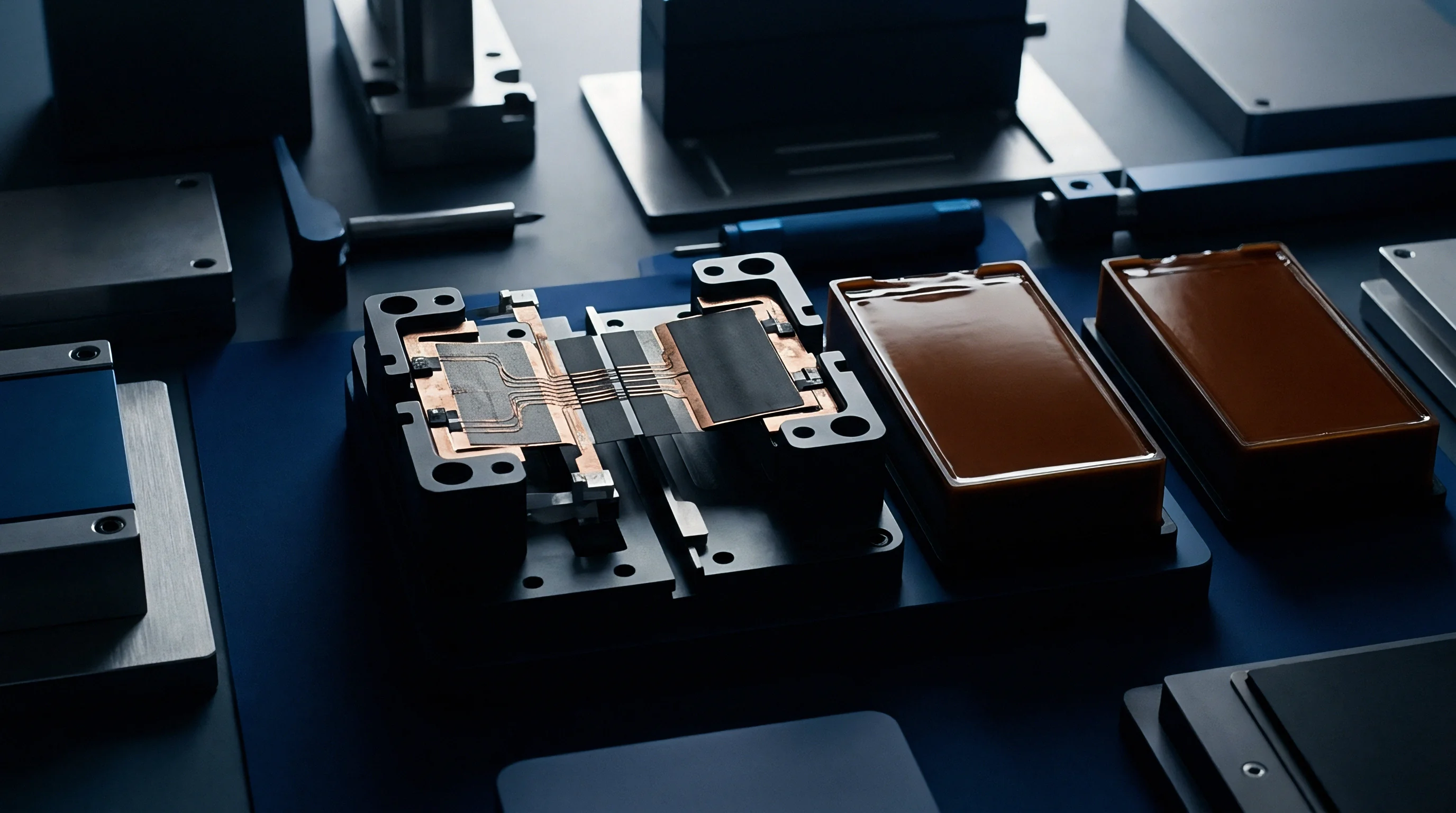
Quantitative Tool Life Calculation and Stroke Limits
Thermal sensors record a steady-state shearing zone temperature of one hundred and ninety-five degrees Celsius during continuous operation. At this temperature, the dynamic parabolic growth rate constant for copper-aluminum intermetallics equals zero point six two square micrometers per second. Empirical wear mapping establishes that punch edge radiusing progresses according to a wear factor multiplied by the product of intermetallic thickness and stroke volume.
The calculation sequence walks through four distinct steps to establish the safe tool replacement interval:
- Calculate the effective exposure time per stroke based on press stroke velocity and shear band contact length, yielding an exposure duration of four point two milliseconds per stroke.
- Determine the intermetallic growth per stroke using the dynamic growth constant at one hundred and ninety-five degrees Celsius, yielding a growth rate of zero point zero zero two six micrometers of intermetallic layer per stroke cycle.
- Apply the abrasive wear coefficient for WC-12%Co tungsten carbide interacting with copper aluminide phases, which converts intermetallic layer volume into punch edge radiusing at a rate of zero point zero two three micrometers of edge rounding per ten thousand strokes.
- Divide the available wear margin of fourteen micrometers (terminal radius minus initial radius) by the wear rate per stroke, yielding a maximum safe stroke limit of six hundred and eight thousand strokes.
Converting this absolute stroke limit into operating press hours dictates tool servicing schedules. At three hundred and fifty strokes per minute, six hundred and eight thousand strokes equals twenty-eight point nine press operating hours. Operating the press beyond twenty-nine hours without punch regrinding drives burr heights past the thirty-micrometer drawing limit.
Regrinding restores edge radius. Tool replacement intervals must reflect active operating conditions rather than fixed calendar schedules.

Sensitivity Analysis of Temperature and Punch Speed
Varying stroke frequency alters friction energy, shifting calculated tool lifespan by hundreds of thousands of cycles. Increasing press speed from three hundred and fifty to four hundred and fifty strokes per minute elevates steady-state shearing zone temperatures from one hundred and ninety-five to two hundred and thirty-five degrees Celsius. This forty-degree rise accelerates intermetallic diffusion kinetics significantly.
| Press Speed (SPM) | Interface Temp (°C) | Growth Constant k (µm²/s) | Wear Rate (µm / 10k strokes) | Max Tool Life (Strokes) | Run Time Limit (Hours) |
|---|---|---|---|---|---|
| 250 | 160 | 0.14 | 0.008 | 1,750,000 | 116.6 |
| 300 | 180 | 0.38 | 0.015 | 933,000 | 51.8 |
| 350 | 195 | 0.62 | 0.023 | 608,000 | 28.9 |
| 400 | 215 | 1.25 | 0.041 | 341,000 | 14.2 |
| 450 | 235 | 2.85 | 0.088 | 159,000 | 5.8 |
The data demonstrates an inverse exponential relationship between stamping speed and total tool output cycles. Elevating press speed by twenty-eight percent reduces total punch lifespan by seventy-three percent due to accelerated intermetallic growth. Implementing active chilled air blowers across the punch face suppresses interface heating, maintaining lower growth constants and extending die replacement cycles substantially.
Active cooling systems on high-speed stamping presses reduce shear zone temperatures and extend punch regrind intervals significantly.
Clearance alters shear. Operating with proper thermal mitigation allows tooling to reach higher stroke numbers before edge rounding forces maintenance downtime.
Whether high-frequency ultrasonic monitoring can predict micro-chipping prior to visible burr growth remains an active area of factory line verification.

Dossier
Formal documentation records punch dimension logs, surface roughness trends, and material certificates across each production lot. Establishing a comprehensive tooling dossier ensures traceability when cell packaging defects or edge burr non-conformances arise. Quality audits require clear documentation proving that replacement intervals stem from calculated intermetallic wear limits rather than arbitrary press operator estimates.
Tooling dossier files must accompany every stamping tool set throughout its operational lifespan. These records form the technical bridge between cell design specifications, tooling NRE investments, and line maintenance schedules. Without validated wear tracking files, asserting warranty claims against punch suppliers or defending cell quality metrics during buyer audits becomes impossible.
Tooling Replacement Protocols and Quality Sign-off
Preventative die maintenance uses dimensional audits before press re-authorization. Before releasing a re-ground punch insert back into production, quality inspectors verify edge radiusing, surface roughness, and coating integrity. Microscopic inspection must confirm the complete removal of micro-cracked tool material and residual intermetallic transfer films during the regrind process.
Insufficiency in regrinding depth leaves micro-damaged tool substrate intact. Subsequent production runs on partially restored tooling exhibit accelerated wear rates, reaching terminal burr limits in less than half the calculated standard interval. Sign-off protocols require optical verification that the post-grind edge radius meets initial drawing requirements within a tolerance of plus or minus zero point five micrometers.
Commercial Ownership of Punch Maintenance and Tooling Amortization
Contractual agreements define which party funds replacement die inserts and shoulders production downtime liabilities. Sourcing agreements for battery pack busbars and cell terminal tabs specify whether tooling NRE covers routine punch regrinding or if maintenance exists as a separate unit-price line item. Defining these boundaries prevents disputes when high-speed operations accelerate wear beyond standard expectations.
Clear commercial contracts establish threshold stroke limits tied directly to material specifications. If a buyer mandates a shift to harder clad tab stock or increases press stroke frequency, the resulting surge in intermetallic growth shifts the tool replacement schedule. Sourcing contracts must adjust agreed tool amortization schedules when operational parameters alter calculated intermetallic growth rates.
Shorter regrind cycles preserve expensive carbide die bases far better than running tooling to complete mechanical breakdown.