Dynamic Strain Rate Fracture Boundaries in HPDC Battery Tubs under Asymmetric Multi Axial Impact Loading
Dynamic strain rates elevate cast aluminum yield strength while accelerating fracture under asymmetric multi-axial shear-tension stress states.


Cast
Structural aluminum tray enclosures manufactured for high-voltage battery assemblies undergo severe mechanical hardening when subjected to rapid deformation during vehicle collisions. High pressure die casting delivers thin-wall structural geometry with integrated cooling channels, structural ribs, and perimeter mounting flanges. The rapid solidification rates inherent to high pressure die casting yield refined microstructures, yet non-uniform cooling generates spatial variations in mechanical response.
Under dynamic impact events where strain rates range from 10-1 to 103 s-1, the yield stress and flow behavior of cast aluminum alloys diverge significantly from static tensile test values.
Dynamic flow stress rises sharply.
Alloy selection directly governs this strain-rate sensitivity. Hypoeutectic aluminum-silicon alloys such as AlSi10MnMg and AlSi7MnMg rely on primary alpha-aluminum dendrites surrounded by an aluminum-silicon eutectic phase. When modified with strontium and heat-treated to T6 or T7 tempers, these materials combine structural rigidity with energy absorption capability.
Under high strain rates, dislocation motion through the primary aluminum matrix encounters thermal activation barriers. Higher deformation speeds leave insufficient time for thermal fluctuations to assist dislocations over microstructural obstacles, elevating the effective flow stress.

Alloy Microstructure under High Deformation Velocity
Chemical segregation during rapid solidification creates primary alpha-aluminum dendrites surrounded by fine eutectic silicon networks. Silicon particles act as rigid inclusions within the softer matrix. Silicon particles crack under tension.
Under quasi-static loading, damage accumulation progresses through the gradual cracking of coarse silicon particles followed by microvoid growth in the adjacent matrix. Under dynamic impact loading, the strain rate sensitivity of the matrix alters this failure sequence.
As strain rate increases, the elevated flow strength of the matrix transfers higher stress directly to the brittle silicon phase at lower macroscopic plastic strains. Microvoid nucleation accelerates. Gas pores initiate microvoid coalescence.
High pressure die castings contain trapped gas porosity originating from turbulent mold filling and lubricant decomposition. Under asymmetric impact vectors, these pores act as stress concentration sites where local strain rates exceed the global deformation rate by an order of magnitude.

Dynamic Yield Scaling in High Pressure Die Castings
Dislocation velocity limits within the crystal lattice elevate plastic flow resistance as impact rates exceed one hundred reciprocal seconds. The ratio of dynamic yield strength to static yield strength increases predictably with strain rate, a phenomenon captured through strain-rate-dependent constitutive relationships such as the Johnson-Cook model or the Cowper-Symonds strain rate formulation. In AlSi10MnMg-T7 enclosures, dynamic strain rate enhancement yields an increase in initial yield stress up to 30 percent at strain rates of 500 s-1 compared to quasi-static conditions.
High strain rates suppress ductility. The strain-to-fracture does not remain constant; it contracts as deformation velocity accelerates. This reduction in total plastic elongation limits the total energy absorption of the enclosure tray during asymmetric pole impacts, transferring force into internal cell modules.
| Alloy Grade | Temper Condition | Quasi-Static Yield (MPa) | Dynamic Yield at 500 s⁻¹ (MPa) | Quasi-Static Fracture Strain (%) | Dynamic Fracture Strain at 500 s⁻¹ (%) |
|---|---|---|---|---|---|
| AlSi10MnMg | F (As-Cast) | 140 | 175 | 4.5 | 2.8 |
| AlSi10MnMg | T6 | 270 | 335 | 8.0 | 5.2 |
| AlSi10MnMg | T7 | 210 | 265 | 12.5 | 9.1 |
| AlSi7MnMg | T6 | 240 | 295 | 10.5 | 7.3 |
| Castasil-37 (AlMg3Mn) | F (As-Cast) | 125 | 160 | 18.0 | 14.2 |
Microstructural heterogeneity across the casting geometry modulates this dynamic response. Wall thickness variations between perimeter sills and internal floor webs alter local cooling rates, yielding finer dendritic arm spacing in thin sections and coarser structures in thick rib intersections. Finer microstructures demonstrate superior strain rate tolerance and elevated dynamic fracture toughness.
- Dendritic Arm Spacing Gradients dictate localized microvoid nucleation densities under dynamic impact loading.
- Eutectic Silicon Morphology dictates localized shear band localization when impact speeds exceed ten meters per second.
- Entrained Hydrogen Porosity triggers localized stress concentration that initiates early dynamic cleavage fracture.
- Iron-Rich Intermetallic Phases form needle-like beta-phase structures that act as immediate crack paths under multi-axial shock loads.
Treating dynamic fracture limits as static material constants in crash simulations leads directly to unexpected tub wall splitting during vehicle crash certification tests.


Stress
Mechanical energy transmission across asymmetric impact vectors creates mixed-mode deformation paths that destabilize structural tub walls far below static tensile yield predictions. When an electric vehicle strikes an off-center rigid obstacle, such as an offset pole or localized underbody debris, the battery enclosure experiences multi-axial loading. Side sills buckle under combined compression and bending while bottom shield plates undergo severe membrane stretching, transverse shear, and out-of-plane punching.
Triaxiality governs failure mode transitions.
Stress triaxiality, defined as the ratio of mean hydrostatic stress to equivalent von Mises stress, serves as the primary parameter governing ductile fracture boundaries. Negative stress triaxiality states correspond to compression, zero corresponds to pure shear, 0.33 represents uniaxial tension, and 0.67 indicates equi-biaxial tension. In asymmetric impact events, local stress triaxiality within the battery tub wall sweeps across these regimes in milliseconds.
Under ISO 20823, failure to account for strain-rate-dependent stress triaxiality shifts invalidates crash simulation approval for structural battery tray side sills.

Multi-Axial Loading Paths in Asymmetric Crashing
Side-impact strikes against vehicle battery enclosures deliver non-uniform kinetic energy that forces side sills into combined twisting and bending. Localized shear stress develops along the vertical webs of internal structural extrusions and cast sills, while tension builds along the outer tensile skins. Shear loads dominate asymmetric collisions.
Dynamic deformation alters local load paths continuously as the battery tub deforms around internal module frame hard-points. Asymmetric loading causes non-uniform contact forces between the internal module array and the cast enclosure ribs. This localized pounding introduces rapid high-magnitude shear stresses superimposed on low-triaxiality bending fields, triggering low-ductility shear fracture modes that bypass classic necking phenomena.
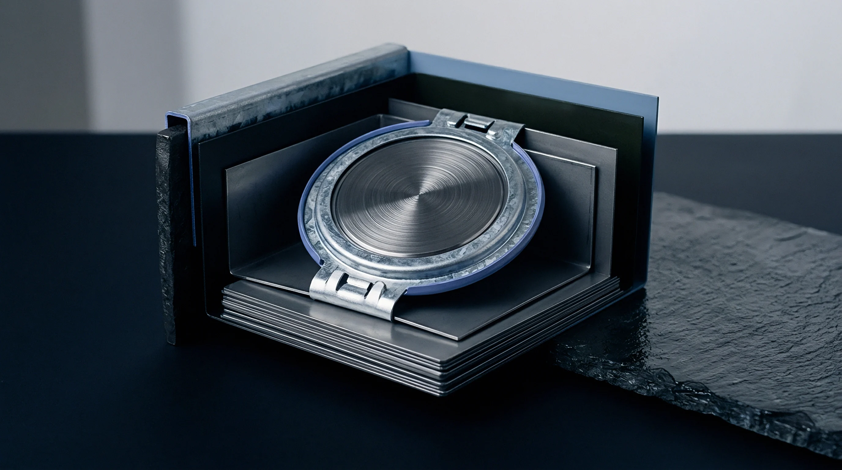
Triaxiality and Lode Angle Sensitivity Functions
Equivalent plastic deformation at rupture varies dramatically across hydrostatic pressure regimes. To capture failure under arbitrary multi-axial loading, fracture models incorporate both stress triaxiality and the Lode parameter, which characterizes the state of shear stress. The Generalized Incremental Stress-State Dependent Damage Model accumulates damage monotonically based on instantaneous strain rate, stress triaxiality, and normalized Lode angle.
The fracture envelope forms a three-dimensional surface in the space of stress triaxiality, Lode parameter, and equivalent plastic strain to failure. Under quasi-static conditions, aluminum alloys exhibit a characteristically lower fracture strain near pure shear than under uniaxial tension. Dynamic strain rates reshape this surface.
High strain rates depress the failure strain curve across positive triaxiality regimes while sharpening the shear-tension valley.
| Deformation Mode | Stress Triaxiality (η) | Normalized Lode Angle (θ̄) | Dominant Fracture Mechanism | High-Rate Strain Sensitivity |
|---|---|---|---|---|
| Pure Compression | -0.33 | -1.0 | Shear Banding / Instability | Low Fracture Sensitivity |
| Pure Shear | 0.00 | 0.0 | Shear Localization | Moderate Strain Rate Hardening |
| Uniaxial Tension | 0.33 | 1.0 | Microvoid Coalescence | High Ductility Suppression |
| Plane Strain Tension | 0.57 | 0.0 | Localized Necking / Tear | Severe Ductility Drop |
| Equi-Biaxial Tension | 0.67 | -1.0 | Cleavage / Void Sheet Tear | Extreme Strain Rate Sensitivity |
Inclusions accelerate shear localization. When asymmetric impact forces push cast aluminum walls into plane strain tension, local strain localization develops rapidly. Dynamic stress states shift the fracture boundary toward smaller plastic strains, converting what appears as a ductile casting under static testing into a brittle splitting failure under 15 m/s impact conditions.
Procurement contracts referencing ISO 20823 specify that suppliers furnish calibrated GISSMO damage parameters derived across four distinct triaxiality states before final tooling sign-off.


Bench
High-speed optical metrology coupled with dynamic hydraulic actuators isolates high-strain-rate material properties from inertial structural ring-down artifacts. Calibrating dynamic damage models requires extracting clean stress-strain data across strain rates spanning four orders of magnitude. Standard servo-hydraulic load frames provide reliable data up to strain rates of 1 s-1.
Higher rate regimes require specialized dynamic testing setups.
Data filtering removes ringing noise.
Split-Hopkinson Pressure Bar systems deliver precise high-strain-rate measurements between 102 and 103 s-1. In tensile configurations, a gas gun launches a striker bar against an input bar, generating a high-amplitude compressive wave that reflects as a tensile pulse at the specimen interface. High-frequency strain gauges attached to the input and output bars record wave propagation, enabling calculation of stress, strain, and strain rate within the gauge section.
At a strain rate of 500 reciprocal seconds, AlSi10MnMg-T7 exhibits a 28 percent yield strength elevation compared to quasi-static bench measurements.
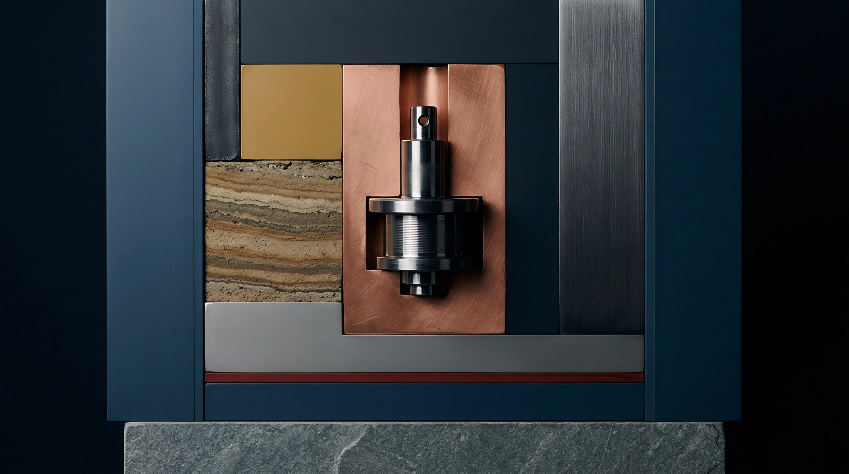
Dynamic Split Hopkinson Pressure Bar Protocols
Stress wave propagation through instrumented striker and transfer rods provides precise force measurement at strain rates up to five thousand reciprocal seconds. Specimen geometry determines the uniformity of stress distribution across the gauge section during high-speed loading. Miniature flat dog-bone specimens with gauge lengths below 5 mm are used to ensure stress equilibrium before fracture occurs.
Inertial forces generate phantom stress peaks if specimen geometry is oversized. Dynamic testing demands rigid fixtures. Special friction-reducing lubricants minimize multi-axial constraint forces at the specimen grips during high-rate compression and shear testing.

High Speed Optical Metrology for Localized Strain
Digital cameras capturing two hundred thousand frames per second track surface speckle patterns to calculate full-field deformation fields. Traditional physical extensometers fail under rapid dynamic loading due to inertial slipping and limited frequency response. Three-dimensional Digital Image Correlation provides contactless strain mapping across the entire specimen surface during dynamic impact.
Optical tracking measures surface strain. High-speed cameras capture localized strain necking, shear band formation, and micro-crack initiation with spatial resolution down to 15 micrometers per pixel. Integrating high-speed image data with force measurements from piezo-electric load cells yields dynamic stress-strain curves free from system resonance chatter.
- Machine miniature multi-axial test coupons directly from critical zones of high pressure die-cast enclosure tubs.
- Apply a high-contrast random speckle pattern using matte black paint over a white base coat with an atomizing airbrush.
- Mount the specimen in a dynamic tension load frame equipped with dual high-speed stereo cameras synchronized to microsecond trigger signals.
- Execute high-rate pull tests at velocities ranging from 0.5 to 15 meters per second to cover target strain rate regimes.
- Process stereo image sequences through digital image correlation software to extract localized stress triaxiality and plastic strain at crack initiation.
- Input experimental failure strains into optimization solvers to calibrate strain-rate-dependent GISSMO damage exponent surfaces.
Foundry sales teams frequently argue that high-strain-rate tensile failure in sample bars results from fixture vibration rather than inherent cast porosity.
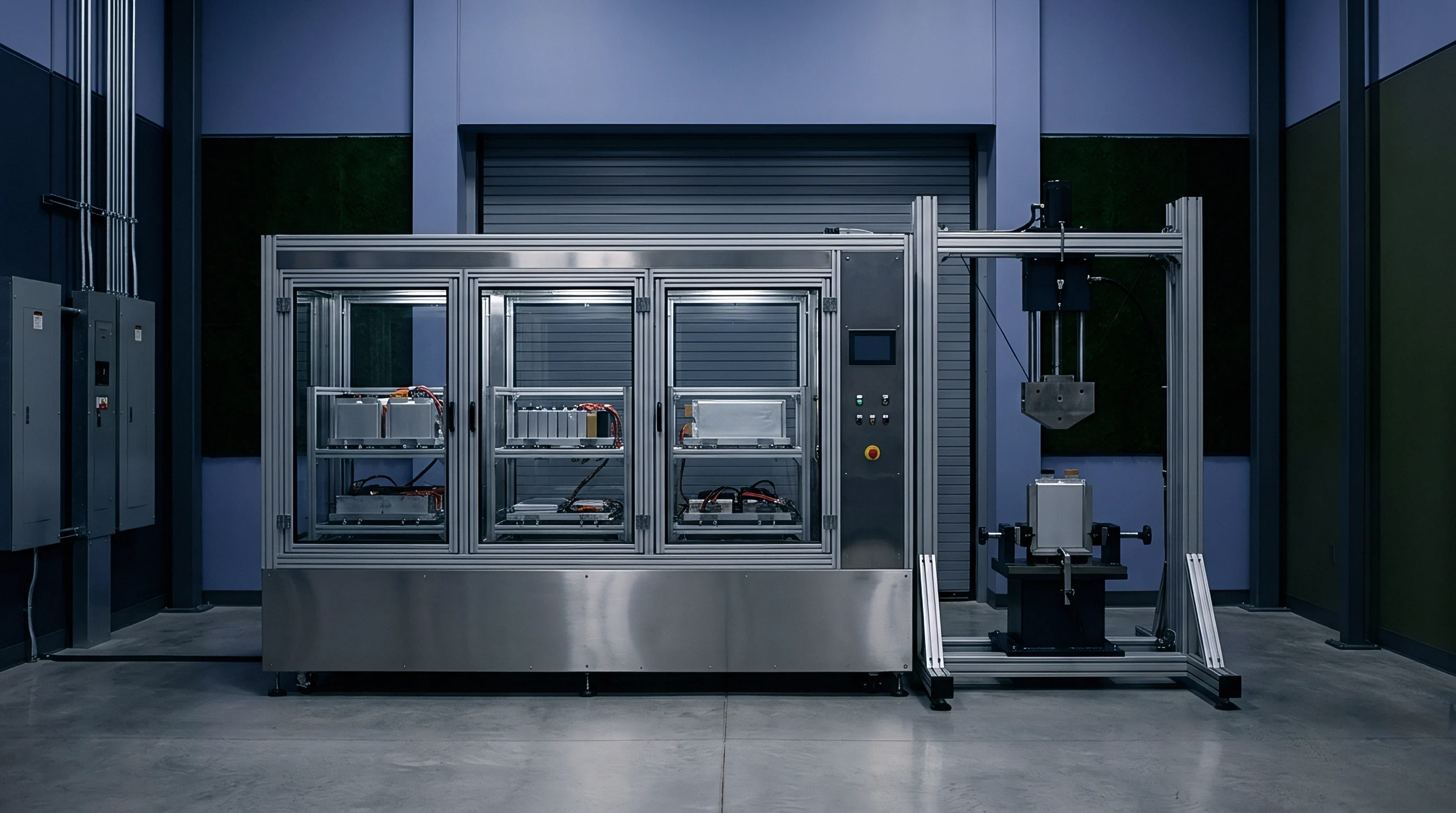

Notch
Geometric transitions at internal structural stiffeners create localized strain accumulation zones where macroscopic energy absorption drops abruptly. Die-cast battery trays incorporate complex rib patterns to support heavy cell modules, distribute crash loads, and maintain structural stiffness. Internal corner radii, rib intersections, wall-thickness step-downs, and ejector pin bosses form severe structural discontinuities.
Under asymmetric impact vectors, these geometry features generate localized stress fields with elevated triaxiality.
Local thinning precedes macroscopic rupture.
Tooling draft angles alter wall thickness. Draft angles required for casting ejection create slight wall tapers, producing localized stress concentrations at the base of thin internal ribs. When asymmetric loading forces cell modules against these internal ribs, high shear stresses concentrate at the fillet radius joining the rib to the bottom shield floor.
If the fillet radius is smaller than 2.0 mm, stress concentration factors exceed 2.2 under quasi-static loading and increase further under high strain rates.
Will Asymmetric Strain Rate Sensitivity Shift Shear Boundaries?
Experimental testing under pure torsion reveals that high deformation speeds compress the failure envelope along negative stress triaxiality axes. Under asymmetric loading, side impact energy induces a combined shear and bending state at internal tray corners. As deformation velocity rises from static rates to 10 m/s, the critical failure strain at these corner fillets drops by up to 40 percent.
The material at the fillet root reaches its strain rate-dependent fracture limit long before the bulk plate wall yields. Cast voids concentrate local shear. Gas pores situated near internal corner radii aggravate this condition.
When high strain rate deformation sweeps through a notched region containing subsurface porosity, micro-cracks form instantly between adjacent pores, triggering rapid shear band propagation across the structural web.
Internal radius transitions that experience combined shear and tension fracture earlier than structural walls subjected to pure compression.

Worked Damage Accumulation Calculation at Stiffener Radius
Consider a four-millimeter die-cast aluminum enclosure wall subjected to an oblique impact generating an instantaneous strain rate of three hundred reciprocal seconds. The local geometry features an internal rib fillet radius of 1.5 mm, resulting in a localized stress triaxiality value of 0.52 (plane strain tension regime). The baseline static fracture strain for the AlSi10MnMg-T6 material at this triaxiality equals 0.095.
Applying the strain-rate sensitivity reduction factor, the dynamic fracture strain scales according to:
εf,dynamic = εf,static ×
Assuming a calibrated strain rate softening parameter Cε = 0.042 and reference strain rate ε̇0 = 0.001 s-1:
εf,dynamic = 0.095 ×
εf,dynamic = 0.095 × = 0.095 × = 0.0447
The dynamic fracture strain decreases to 4.47 percent equivalent plastic strain. The GISSMO damage accumulation rule calculates damage growth incrementally:
ΔD = (n / εf,dynamic) × D(1 – 1/n) × Δεp
With a damage accumulation exponent n = 1.6, an initial accumulated damage D = 0.20, and a plastic strain increment Δεp = 0.008 during a single time step of the collision event:
ΔD = (1.6 / 0.0447) × (0.20)(1 – 0.625) × 0.008
ΔD = 35.794 × (0.20)0.375 × 0.008 = 35.794 × 0.549 × 0.008 = 0.157
The accumulated damage jumps from 0.20 to 0.357 in a single computational increment. Once total damage D reaches 1.0, element deletion occurs, modeling crack initiation at the rib fillet. Static material models fail to predict this rapid element deletion, overestimating the structural integrity of the battery tub during severe side impacts.
It remains uncertain whether dynamic thermal softening within adiabatic shear bands offsets work hardening before microvoid coalescence initiates macroscopic tear propagation at internal rib corners.

Audit
Verification routines for structural battery enclosures require rigorous spatial mapping of internal density variations across primary structural load paths. Quality assurance for high pressure die-cast battery tubs extends beyond surface dimensional inspection. Because dynamic strain rate fracture boundaries depend heavily on microstructural density and void distributions, incoming inspection routines must verify internal casting quality against dynamic failure thresholds.
Porosity reduces local load area.
Industrial X-ray systems resolve internal void distributions down to twenty micrometers across complex geometric cross-sections. VW 50093 and VDA 257 standards establish porosity classification grids for structural castings, categorizing internal defects by pore diameter, total pore volume percentage, and spatial proximity to adjacent voids. Structural crash-critical zones, such as perimeter sills and module mounting points, require strict defect class controls.
Volumetric gas porosity above one percent accelerates void nucleation and shifts dynamic failure boundaries toward lower equivalent plastic strains.

Computed Tomography Inspection Standards for Structural Trays
Industrial X-ray systems resolve internal void distributions down to twenty micrometers across complex geometric cross-sections. Full-field volumetric scanning identifies subsurface gas inclusions, shrinkage porosity arrays, and oxide film entrainments that escape two-dimensional radiographic projection. Gas pores larger than 0.5 mm situated within 1.0 mm of the surface act as primary initiation sites for dynamic shear tear failures.
Inclusions accelerate shear localization. Quantitative computed tomography analysis maps the precise volumetric pore density across high-stress zones. Foundries must maintain total volumetric porosity below 0.8 percent in primary crash impact zones to preserve dynamic strain energy density capabilities.
| Defect Severity Class | Max Pore Diameter (mm) | Volumetric Density (%) | Allowable Wall Thickness Strain Loss (%) | Crash-Critical Zone Compliance |
|---|---|---|---|---|
| Class P1 (Critical) | 0.30 | 0.5 | 3.0 | Fully Approved for Perimeter Sills |
| Class P2 (Structural) | 0.60 | 1.0 | 7.5 | Approved for Internal Webs Only |
| Class P3 (Standard) | 1.00 | 2.0 | 15.0 | Restricted to Mounting Tabs |
| Class P4 (Non-Structural) | 1.80 | 4.0 | 30.0 | Rejected for Load-Bearing Battery Tubs |
Coupon Extraction Rules for Dynamic Fracture Verification
Specimens milled directly from production tray castings preserve localized cooling rate microstructures and residual stress states. Standard separately cast tensile bars yield optimistic strain-to-fracture data because ideal mold geometries minimize gas entrainment and optimize cooling rates. Dynamic fracture boundary verification demands testing specimens cut directly from the finished HPDC enclosure tray.
Extraction maps prioritize high-stress regions identified through FEA asymmetric crash simulations. Test coupons extracted from internal floor webs, side sill corners, and rib bases undergo dynamic tensile and shear testing to confirm that the production casting matches the constitutive failure parameters used in vehicle safety approval models.
- Perimeter Sill Coupon Sets verify dynamic tensile fracture limits along primary vehicle side-pole impact impact zones.
- Floor Shield Shear Specimens verify high-rate shear failure strains under localized underbody punch loading.
- Rib Corner Extracted Blocks verify stress triaxiality failure thresholds under multi-axial compression-tension bending.
- Tooling Gate Region Samples verify microstructural ductility at maximum oxide film entrainment locations.
Components extracted from regions near the shot sleeve entrance exhibit superior energy absorption compared to metal that fills distant thin-wall ribs.