Evaluating Radiant Flux Boundaries for Reduced Energy Storage System Clearances
Reduced energy storage clearances require UL 9540A full-scale fire test proof showing adjacent cabinet radiant flux stays below 12.5 kW/m² to prevent fire spread.

Distancing
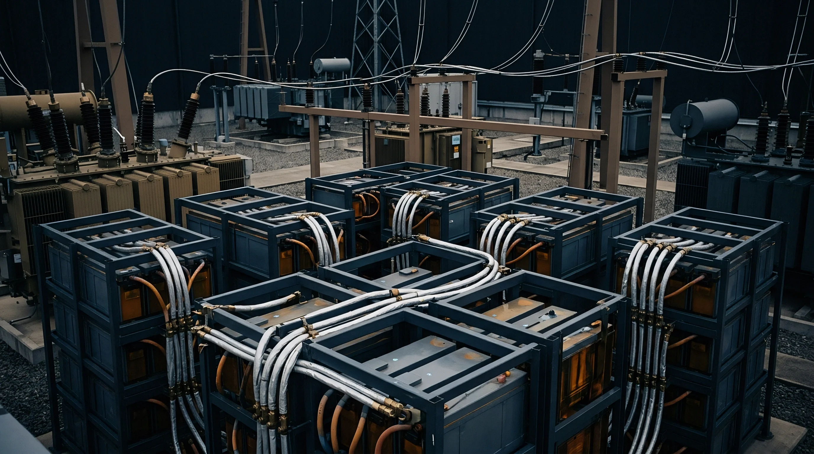
National fire codes establish three feet of open air around stationary energy storage enclosures as the baseline boundary to stop thermal runaway propagation between battery cabinets and adjacent structural exposures. Section 1207 of the International Fire Code and Chapter 4 of NFPA 855 impose this 914 mm spatial envelope to restrict heat transfer, permit firefighter access, and ensure that gas venting remains unconfined. Commercial project developers facing restricted land parcels or urban building footprints routinely seek clearance reductions down to zero inches.
Achieving regulatory approval for compressed spacing depends on proving that radiant heat emitted during a maximum credible fire event stays below critical ignition thresholds for adjacent target surfaces.
Code authorities evaluate boundary reductions through performance-based engineering filings rather than prescriptive allowances. When a lithium-ion cell undergoes thermal runaway, energetic gas venting produces localized jet flames with surface temperatures exceeding 1000 degrees Celsius. The resulting radiative load radiates outward, casting thermal energy onto neighboring cabinet skins, wall assemblies, and exposed electrical hardware.
Safety standard evaluation requires proving that the peak radiant flux impinging on adjacent equipment remains below the critical flux value required to initiate thermal breakdown or cascade cell failure in adjacent systems.
Fire barrier performance validation requires demonstrating that incident thermal energy on targeted equipment remains below specific material breakdown thresholds throughout full-scale burn testing.
Critical thermal boundaries vary according to the material composition of the target structure and the exposure duration. Standard engineering values establish specific radiant flux limits where target degradation occurs:
| Radiant Flux Boundary (kW/m²) | Exposure Limit Duration | Physical Impact on Target Surface | Regulatory Significance |
|---|---|---|---|
| 1.4 | Continuous | Long-term human skin pain threshold | Personnel egress clearance minimum |
| 4.7 | 30 minutes | Pilot ignition threshold for common polymers and wood | Minimum boundary for unprotected combustible walls |
| 12.5 | 10 minutes | Melting of cable jacketing and plastic enclosures | Standard maximum allowance for adjacent battery cabinet skins |
| 20.0 | 5 minutes | Autoignition of structural materials and internal cell runaway initiation | Critical threshold causing immediate thermal runaway propagation |
| 37.5 | Instantaneous | Structural steel deformation and structural integrity failure | Catastrophic structural destruction limit |
Engineers calculate heat transfer across narrow gaps using radiative view factors, cabinet surface emissivities, and peak heat release rate measurements derived from standardized fire tests. Reducing physical spacing from 914 mm to 76 mm increases the view factor between cabinet skins toward unity, multiplying the localized heat flux by up to eight times. Without intermediate passive thermal shielding or active fire suppression intervention, unmitigated radiant flux across narrow clearances induces thermal runaway in neighboring battery modules within minutes of initial vent ignition.
Special permit approvals rely entirely on verified testing documentation rather than numerical simulation alone. The prescriptive exemption language within NFPA 855 Section 4.3.2 grants local code officials the statutory authority to approve reduced clearances only when full-scale fire testing demonstrates that fire will not spread to adjacent energy storage units or exposed wall structures. The formal safety dossier submitted for plan review must tie specific spatial dimensions directly to verified test data collected under full-scale burn conditions.
Radiation
Thermal energy transfer during a battery fireside event occurs through radiative emission from high-temperature flame plumes and incandescent gas vents. Convection carries superheated exhaust gases upward, but radiation dominates horizontal heat transfer across open clearances to neighboring enclosures. Quantifying the radiant flux distribution requires modeling the fire as a geometric radiant emitter with an effective surface emissive power derived from the total heat release rate and flame area.
Stefan-Boltzmann physical laws dictate that radiant heat emission scales with the fourth power of absolute temperature. A burning lithium nickel manganese cobalt oxide battery pack reaches peak flame temperatures near 1200 degrees Celsius, producing a surface emissive power exceeding 150 kW per square meter of flame surface. Lithium iron phosphate formulations generate lower peak gas temperatures near 900 degrees Celsius, yet their prolonged combustion durations emit sustained radiative flux levels capable of igniting adjacent plastics and cable sheaths over extended exposure windows.
A high-capacity cell experiencing thermal runaway releases radiative heat that increases exponentially with absolute flame temperature.
Calculating the incident radiant flux hitting an adjacent surface utilizes the spatial geometry between the flame and the target skin. The mathematical formula defines the physical boundary parameters:
q” = ε · σ · F · (T_flame⁴ – T_target⁴)
The variable q” represents the net radiant flux received at the target surface, measured in kilowatts per square meter. The surface emissivity ε of typical powder-coated steel enclosures ranges between 0.85 and 0.92, indicating high absorption of radiative thermal energy. The Stefan-Boltzmann constant σ equals 5.67 times 10 to the power of minus 8 Watts per square meter Kelvin to the fourth power.
The geometric view factor F accounts for the spatial alignment, distance, and angular orientational exposure between the burning cabinet skin and the target enclosure.
Narrow spatial gaps elevate the view factor F close to its maximum theoretical limit of 1.0. When two battery enclosures sit separated by only 100 mm, virtually all thermal energy emitted by the compromised cabinet face strikes the adjacent cabinet skin. Convective airflow in constrained channels becomes restricted, creating a stagnant hot air boundary layer that limits convective cooling while radiative transfer drives skin temperatures beyond 500 degrees Celsius in under two minutes.
The total heat release rate profile determines how long high flux levels persist against adjacent boundaries. Battery fires exhibit rapid growth phases characterized by gas venting, deflagration of combustible electrolytes, and structural fire growth involving plastic module casings and busbar insulation. Peak heat release rate values for commercial 100 kWh battery racks frequently reach between 1.5 MW and 3.5 MW, producing radiant flux fields that exceed critical ignition limits across clearances under two meters unless interrupted by passive physical barriers.
Flames exiting cabinet ventilation louvers form directional gas jets that distort the spatial radiation profile. Horizontal gas discharge directs intense radiant and convective energy straight toward neighboring cabinet walls, bypassing top-mounted thermal relief paths. Enclosure engineering requires verifying that louver orientation and pressure relief doors direct flaming exhaust away from adjacent storage units to maintain safe radiant flux boundaries.
Shielding
Passive thermal protection barriers absorb, reflect, and insulate against extreme radiative flux loads to permit compressed installation footprints. Positioning specialized material shields between battery cabinets or integrating layered composite panels into cabinet side walls intercepts radiant energy before it heats internal components. Engineering an effective radiant boundary shield demands selecting materials capable of resisting physical erosion from flaming gas jets while maintaining low thermal conductivity at elevated temperatures.
Material selection determines how thin a thermal barrier can be specified while maintaining required clearance reductions. Standard sheet metal construction provides negligible thermal resistance during sustained exposure. Steel rapidly conducts heat across its thickness, transforming an exterior cabinet wall into a high-temperature radiant emitter on its interior face.
Multilayer passive insulation assemblies combine structural outer skins with low-density insulating cores to delay thermal conduction.
Common industrial insulation materials exhibit widely varying performance characteristics under intense radiative exposure:
| Shield Composition | Thickness (mm) | Unexposed Face Temp Rise at 30 Min (°C) | Mechanical Integrity Under Jet Flame Exposure |
|---|---|---|---|
| Single steel sheet (baseline) | 2.0 | +480 | Deforms rapidly; maintains continuous barrier |
| Calcium silicate board | 25.0 | +110 | Resists flame breakdown; heavy structural mass |
| Intumescent coated steel | 3.0 | +210 | Expands to form insulating char; vulnerable to erosion |
| Microporous silica panel | 12.5 | +45 | Superior insulation; requires protective steel encasement |
| Ceramic fiber blanketing | 50.0 | +65 | Excellent thermal resistance; susceptible to air erosion |
Engineers combine distinct material layers within cabinet enclosures to maximize thermal reflection and minimize heat conduction. Highly reflective outer coatings or stainless steel outer skins reflect up to 70 percent of incoming radiant energy during early fire stages. An underlying core of microporous silica or calcium silicate blocks conductive heat flow, preventing the internal cabinet wall temperature from exceeding the 120 degree Celsius threshold where lithium-ion cell degradation accelerates.
Integrating passive shielding into energy storage designs introduces mechanical and operational failure mechanisms that must be addressed during qualification:
- Intumescent layer ablation occurs when high-velocity vent gases scour away expanding insulating char, leaving underlying metal exposed to direct flame contact.
- Thermal bridging through fasteners provides localized high-conduction paths through insulation cores, creating dangerous hot spots on internal enclosure walls.
- Moisture absorption in porous boards leads to steam generation and internal pressure build-up within sealed cabinet walls during rapid heating events.
- Structural warping of thin skins creates open gaps along panel seams, allowing direct radiant heat and hot vent gases to bypass the barrier envelope.
- Vibration-induced insulation settling during transit creates uninsulated void spaces near the top of vertical cabinet side walls.
Dense passive insulation cores retain mechanical stability under high radiative heat loads where thin intumescent surface coatings erode away.
Design teams that install thin unverified fire blankets without structural steel cladding risk rapid mechanical barrier failure under real-world fire conditions. High-velocity gas vents stripping away soft insulation layers expose adjacent cell modules directly to intense radiative output, causing instant cascading failures.
Testing
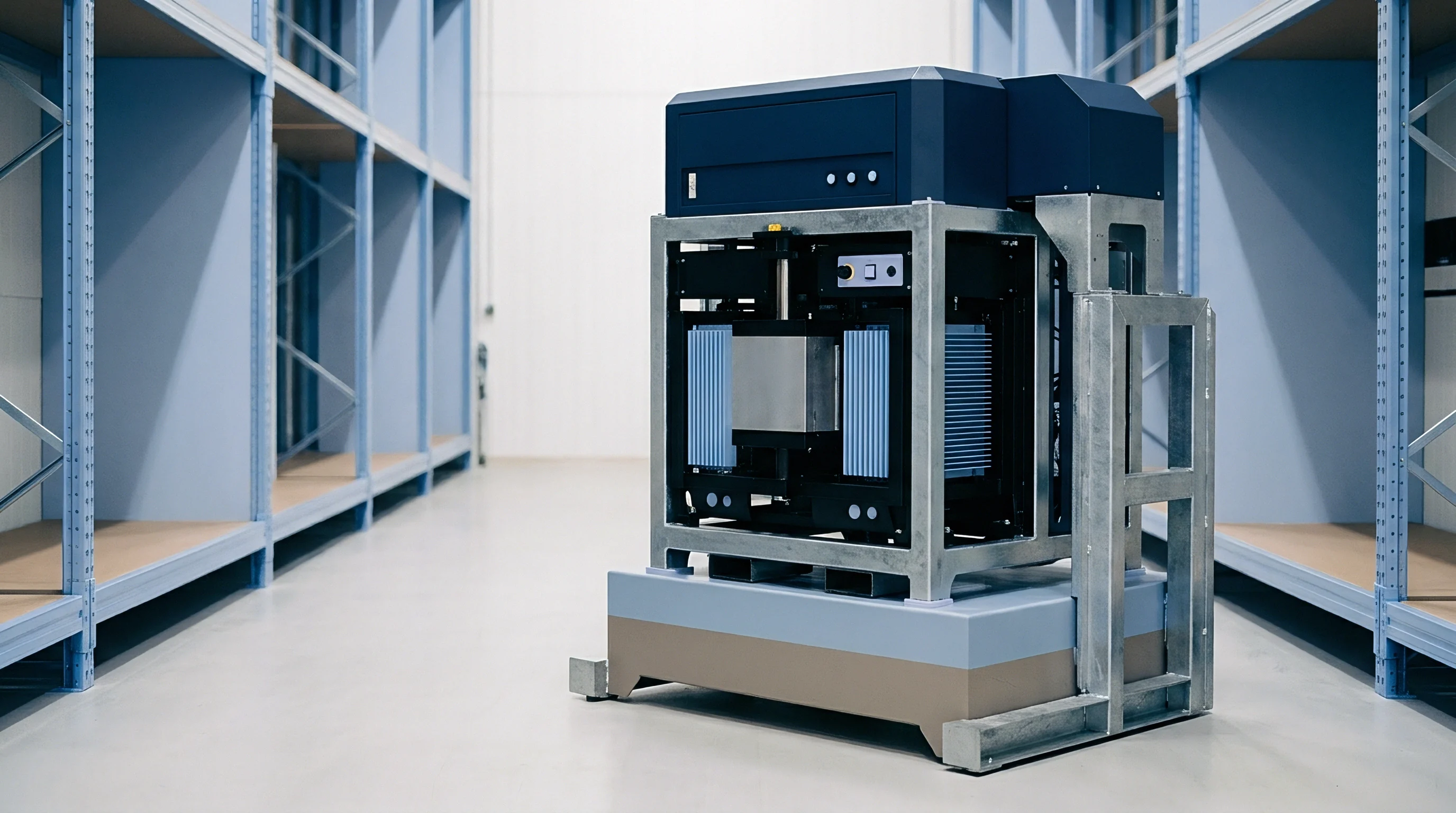
UL 9540A standardized methodology provides the formal testing protocol for evaluating thermal runaway fire propagation in energy storage systems. The test standard measures heat release rates, gas compositions, flame lengths, and radiant heat flux levels at cell, module, unit, and installation levels. Data collected during unit-level testing directly establishes whether an energy storage enclosure qualifies for reduced spatial clearances under local building and fire codes.
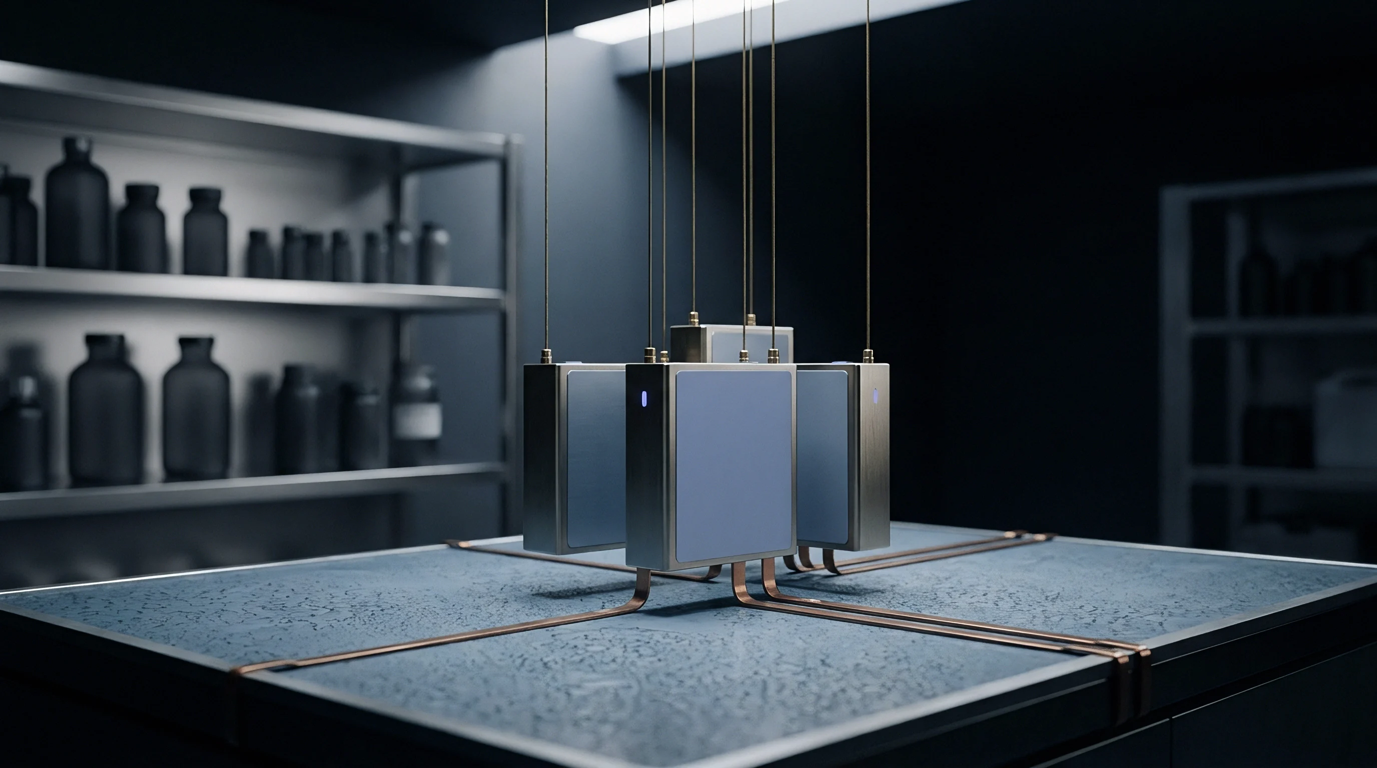
Unit-level UL 9540A testing forces a central lithium-ion cell into thermal runaway using internal film heaters or overcharge mechanisms while monitoring conditions throughout the target rack. Radiometers and heat flux transducers installed at defined distances around the target unit quantify the thermal energy field radiating outward. Water-cooled Schmidt-Boelter gauges measure total radiant flux at target distances corresponding to candidate clearance reductions, such as 3 inches, 6 inches, and 12 inches from the cabinet surface.

Which Flux Level Triggers Thermal Runaway Propagation?
Thermal runaway propagation inside adjacent enclosures begins when the internal cell surface temperature exceeds its threshold for solid electrolyte interphase breakdown, typically between 120 and 140 degrees Celsius. Achieving this critical internal temperature requires a sustained external heat flux striking the cabinet exterior. If the exterior radiant flux exceeds 12.5 kW per square meter, heat conducts through standard steel walls fast enough to raise adjacent internal cell temperatures past their critical limit within six minutes, triggering runaway cascade.
Extracting accurate boundary data during full-scale burn testing requires rigorous instrument setup and execution:
- Calibrate all Schmidt-Boelter heat flux transducers against standard blackbody radiation sources to verify linear output sensitivity.
- Mount radiant heat flux gauges at vertical mid-height and top edges of surrounding target boundary frames where flame plumes concentrate.
- Install internal surface thermocouples behind target enclosure walls to correlate exterior radiant flux loads with interior skin temperature rise.
- Initiate thermal runaway in the primary cell cluster and log gas temperature, heat release rate, and radiative flux continuously at 1 Hz intervals.
- Maintain active measurement for a minimum of two hours following peak flame activity to capture long-term conductive soaked heat transfer.
- Inspect adjacent target structures for charring, melting, structural deformation, or internal cell temperature degradation.
Test reports issued by accredited laboratories specify the exact physical boundaries where radiant flux dropped below regulatory limits. If testing shows that the maximum flux recorded at 76 mm from the unit face never exceeded 3.5 kW per square meter during the entire burn event, the system demonstrates compliance for 3-inch side-by-side spacing.
Section 8.4 of UL 9540A mandates that heat flux sensors capture both total thermal flux and isolated radiative heat transfer to prevent convective mixing from skewing boundary calculations.
System suppliers sometimes claim that internal water mist or chemical suppression systems eliminate the need for physical separation testing. Code officials reject these claims because suppression systems can fail, run out of agent, or suffer electrical loss during initial deflagration events. Test reports must reflect passive safety performance without active suppression assist to establish legal clearance boundaries under NFPA 855 guidelines.
Stipulation
Securing local building permits for energy storage systems with reduced clearances requires translating lab test summaries into legally binding regulatory filings. Authorities Having Jurisdiction, including local fire marshals and plan reviewers, hold statutory power to accept or reject performance-based clearance reductions. Submitting an incomplete UL 9540A test summary without comprehensive boundary flux maps guarantees plan refusal and project approval delays.
A complete engineering clearance dossier must establish a clear chain of evidence connecting raw burn test measurements to site-specific spatial layouts. The filing package requires specific documentation to substantiate performance-based design requests:
- Full UL 9540A Unit Level Test Report containing complete heat release rate curves and raw radiant flux transducer channel outputs.
- Site-Specific Peer Review Analysis authored by an independent licensed fire protection engineer validating the thermal boundary calculations.
- Enclosure Structural Drawings highlighting spatial dimensions, wall material thickness, internal insulation specifications, and door latch retention strength.
- Emergency Operations Plan detailing firefighter access clearances, gas venting directions, and isolation shutoff locations.
- Manufacturer Specification Sheet confirming that field-deployed battery cabinet configurations match the exact test unit baseline without material variations.
Discrepancies between tested units and field-deployed equipment create significant legal exposure. Upgrading battery cells to higher energy density chemistry within the same cabinet shell invalidates previously certified UL 9540A boundary data. A cabinet qualified with 280 Ah LFP cells cannot claim reduced clearances if installed with 314 Ah cells without re-running thermal runaway testing or filing a formal engineering review that proves heat release rate profiles remain unchanged.
Plan approval conditions frequently mandate secondary risk mitigation measures when clearances approach zero inches. Local fire officials may require specialized thermal barriers on interior room walls, elevated gas detection sensitivity, or dedicated thermal imaging camera loops tied into site control networks. Documenting these stipulations directly within permit approval contracts establishes a legally enforceable standard of operation for the life of the asset.
Will future revisions of international fire codes replace individual project engineering waivers with standardized look-up tables based on certified heat release rate tiers?

Exposure
Deploying energy storage equipment under compressed clearances creates major commercial exposure across insurance underwriting, property damage liability, and warranty enforcement. Insurance underwriters evaluate battery assets using fire risk models that penalize reduced spatial separations unless backed by comprehensive testing data. A site designed with unauthorized clearance reductions faces dramatic premium surges or complete property damage coverage exclusions.
Commercial contracts must clearly assign regulatory compliance liability between system integrators, project developers, and engineering, procurement, and construction contractors. If an installation suffers a fire event that spreads to adjacent enclosures due to uncertified clearance reductions, liability shifts to the party that certified the spatial layout. Contract clauses specifying energy storage procurement must mandate that the equipment manufacturer indemnifies the owner against all losses stemming from unapproved boundary modifications.
Warranty provisions issued by battery OEMs contain strict environmental and spatial installation limits. Operating cabinets below minimum clearance thresholds can restrict natural convective cooling around enclosure skins, driving elevated internal ambient temperatures that accelerate cell capacity degradation over time. Manufacturers routinely reject warranty claims for premature capacity loss if site audits reveal that side-by-side clearances were compromised below manual specifications during installation.
Financial exposure extends to asset foreclosure or municipal shutdown orders if code enforcement officers discover non-compliant clearances post-commissioning. Remediation costs for re-spacing battery enclosures on a fully constructed site far exceed the initial land savings achieved by compressing the layout. Re-routing buried high-voltage conduit, pouring new concrete pads, and re-certifying electrical connections can cost millions of dollars, completely destroying project returns.
Validating radiant flux boundaries through verified testing and securing formal AHJ approval prior to site construction remains the only path to protect capital investments.