Establishing Baseline Mechanical Strain Envelopes for Commercial Battery Module Warranties
Establishing module strain envelopes requires setting 0.15 to 1.20 MPa stack pressure limits to bind cell warranty claims to verified mechanical boundaries.


Displacement
Prismatic and pouch lithium-ion cells change dimension continuously as they cycle and age. Intercalating lithium ions into graphite anodes expands the lattice by roughly 10 percent at full lithiation. Silicon composite anodes magnify this breathing, expanding in volume past 20 percent during active cycling.
In pouch cells, that internal dilation shows up directly as increased thickness across the cell face. Hard-cased prismatic cells push that internal expansion outward, bowing the aluminum can sidewalls. Cell manufacturers specify initial thickness tolerances at nominal shipping state of charge, but designing a module requires defining displacement boundaries across thousands of operating cycles.
Mechanical strain inside an active module stems from two physical sources. Reversible breathing tracks the charge and discharge cycle directly. Irreversible swelling accumulates steadily over service life as the solid electrolyte interphase grows, active material isolates, and decomposing electrolyte continuously off-gasses.
Early module design determines whether the retention structure accommodates this motion through compliance or holds it fixed with rigid clamping.
Unconstrained cell swelling accelerates electrode delamination under fast charge profiles.
Establishing baseline displacement curves requires standardized measurements taken under controlled thermal conditions. Mechanical dial indicators or laser displacement sensors track thickness changes during constant-current cycling. Under unconstrained conditions, pouch cells can expand by 4 to 8 percent of their original thickness within the first 500 equivalent full cycles under 1C charging rates.
When held rigidly, those same expanding active materials exert heavy normal forces against the restraint plates.

Electrode Breathing Characteristics
Cathodes shift volume far less than graphitic anodes during cycling. Lithium iron phosphate contracts by roughly 6.5 percent during delithiation, which partially offsets anode expansion on charge. Nickel manganese cobalt oxide cathodes show anisotropic lattice strain between 1 to 3 percent depending on nickel stoichiometry.
In high-nickel compositions, cyclic mechanical stress above the tensile strength of polycrystalline grains causes microcracking along primary particle boundaries.
| Chemistry Type | Anode Composition | Reversible Breathing Range | Irreversible Swelling at 80 Percent SOH | Peak Swelling Pressure at 1.0 MPa Preload |
|---|---|---|---|---|
| LFP | Synthetic Graphite | 1.2 to 2.5 percent | 3.0 to 5.5 percent | 0.35 to 0.65 MPa |
| NMC 622 | Natural Graphite | 2.0 to 4.0 percent | 4.5 to 7.0 percent | 0.50 to 0.85 MPa |
| NMC 811 | Graphite-Silicon 5wt% | 3.5 to 6.5 percent | 6.5 to 11.0 percent | 0.80 to 1.45 MPa |
| NMC 9055 | Graphite-Silicon 10wt% | 5.0 to 9.0 percent | 9.0 to 16.0 percent | 1.20 to 2.10 MPa |
As cells age from new to end of life, internal loads shift from localized point contacts to broad planar compressive fields. Packaging materials within the module either absorb these structural loads or transfer them straight to the chassis mounts.
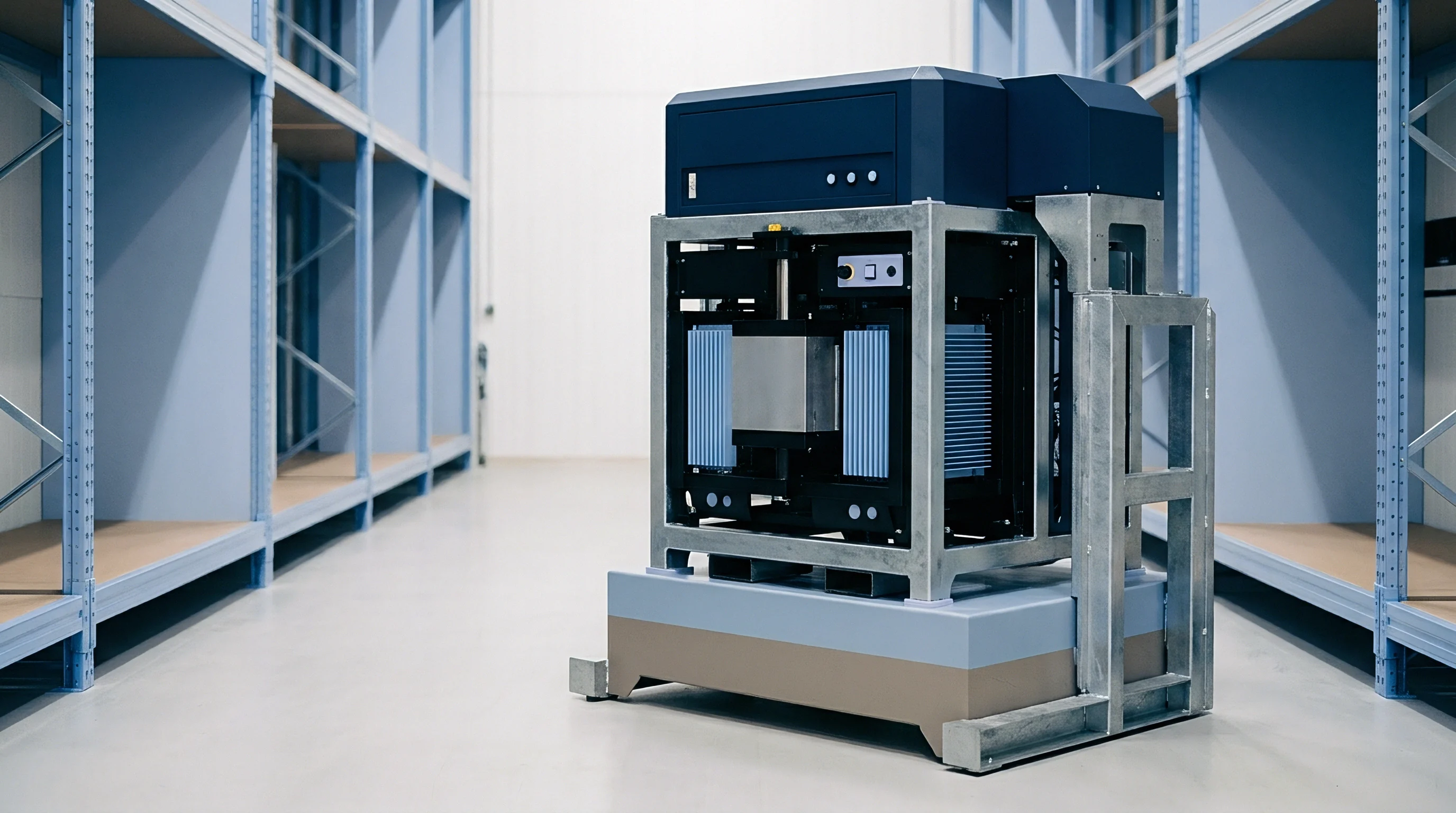

Clamp
Endplates and tie rods maintain uniform stack pressure across a cell group. Without sufficient compression, layers separate near the center of the electrode face, raising interfacial resistance and encouraging lithium plating. Over-compressing crushes the porous separator, which chokes electrolyte flow and risks internal micro-shorts from dendrite growth.
Clamping specs fix these physical limits by setting assembly preload, maximum endplate flex, and tie-rod yield strengths.
Module retention strategies take a few standard approaches:
- Rigid Endplate Systems use cast aluminum or stamped high-strength steel plates bound by welded side straps or tension rods to hold module length constant over service life.
- Spring-Loaded Retention places wave springs, disc springs, or calibrated elastomeric pads between cells to keep stack pressure relatively steady as cell thickness grows.
- Semi-Compliant Structural Foam fills interstitial spaces with closed-cell polyurethane or silicone cushions that absorb assembly tolerances and permit controlled breathing while preserving baseline contact pressure.
- Direct Adhesion Frameworks bond prismatic can faces to structural cooling fins with polyurethane adhesive, transferring swelling forces into shear loads across the baseplate.
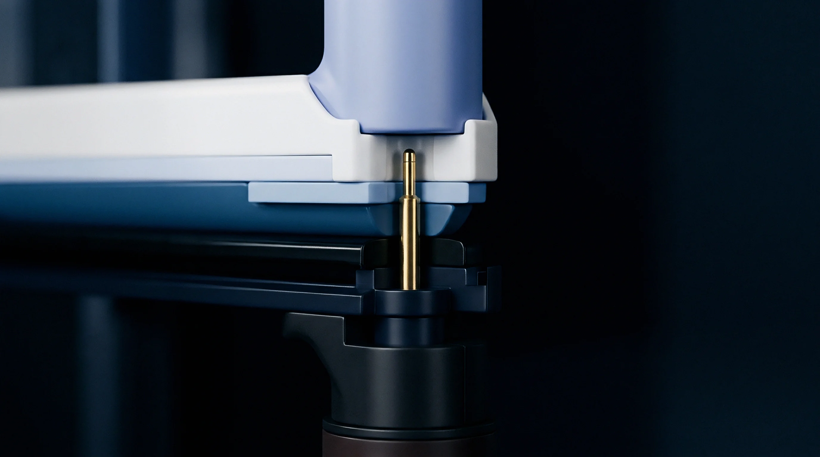
Retention Structure Deflection Modes
Endplates bow under the expansion forces of cycling cells. Because the center deflects outward, compression concentrates along the cell edges rather than the middle. Finite element analysis guides ribbing layouts to keep this deflection below 0.3 millimeters under peak end of life swelling forces.
Without even contact pressure, localized current density hotspots form and accelerate thermal degradation.
Section 6 of typical commercial module supply agreements limits peak structural wall deflection to 0.5 millimeters across all operational temperatures.
Tie rods and side straps absorb the continuous tensile reaction load. Tension bands stamped from austenitic stainless steel deliver high yield strength and corrosion resistance without adding much width to the module. Tie-rod elongation under peak thermal and swelling loads must be calculated so the metal stays strictly within its elastic limit throughout the warranty duration.
Setting the right stack pressure means balancing long-term electrochemical stability against the weight of the retention hardware.


Tolerance
Dimensional stack-up calculations set the starting envelope for commercial modules. A module holding twenty-four prismatic cells builds up tolerance variations from can manufacturing, insulating PET wraps, thermal gap pads, and internal separators. Cell suppliers deliver prismatic units with individual thickness tolerances of plus or minus 0.3 millimeters on a nominal 27.0 millimeter width.
Simple arithmetic stacking across an unselected lot of twenty-four cells produces a total potential variation of plus or minus 7.2 millimeters.
Statistical tolerancing shrinks this projected envelope through root-sum-square analysis. On the line, variation is kept in check by binning incoming cells by thickness before loading them into modules.
- Incoming Metrology measures bare cell thickness under a calibrated 0.3 MPa planar contact load to establish actual baseline dimensions.
- Bin Assignment sorts cells into 0.1 millimeter thickness bands to prevent extreme stack build-up across production groups.
- Insulation Application checks dielectric foil placement and adhesive thickness across both wide faces of the can.
- Controlled Compression applies target seating force using hydraulic rams while displacement sensors track pack movement.
- Fastener Torquing drives tension bolts to specified torque angles, locking down the mechanical baseline before unclamping.

Worked Stack Compression Calculation
Take an energy storage module built with twelve prismatic cells, each with a nominal thickness of 54.0 millimeters, a width of 174.0 millimeters, and an active face area of 0.035 square meters. Target assembly preload pressure is set to 0.30 MPa, with a maximum allowable end of life pressure of 1.20 MPa. Interstitial elastomeric compression pads start at an uncompressed thickness of 1.50 millimeters and a non-linear compressive modulus of 2.80 MPa.
Cell manufacturing thickness tolerance sits at plus or minus 0.25 millimeters per unit, while pad thickness tolerance sits at plus or minus 0.08 millimeters.
An arithmetic worst-case sum across twelve cells and eleven compression pads (twelve times 0.25 millimeters plus eleven times 0.08 millimeters) yields 3.88 millimeters of total variation. A root-sum-square calculation ~ the square root of twelve times 0.25 squared plus eleven times 0.08 squared ~ gives a statistical variance of 0.905 millimeters. The rigid housing assembly tool must account for this 0.905 millimeter variation so initial preload stays between 0.20 MPa and 0.45 MPa.
A shift of just 0.50 millimeters in compressed pad thickness alters initial face pressure by 0.14 MPa.
| Parameter Stage | Nominal Dimension | Tolerance Band | Resulting Face Pressure | Structural Load on Straps |
|---|---|---|---|---|
| Uncompressed Cell Stack | 648.0 mm | ± 0.905 mm | 0.00 MPa | 0.0 kN |
| Initial Fixture Compression | 642.5 mm | ± 0.350 mm | 0.30 MPa ± 0.08 MPa | 10.5 kN ± 2.8 kN |
| Beginning of Life 100% SOC | 643.8 mm | ± 0.400 mm | 0.42 MPa ± 0.09 MPa | 14.7 kN ± 3.1 kN |
| Mid Life Cyclic Peak | 646.2 mm | ± 0.550 mm | 0.78 MPa ± 0.15 MPa | 27.3 kN ± 5.2 kN |
| Warranty Threshold Limit | 649.0 mm | ± 0.650 mm | 1.20 MPa ± 0.20 MPa | 42.0 kN ± 7.0 kN |
Poor tolerance management during initial assembly leads to fastener failure down the line and uneven cell degradation along the series string.
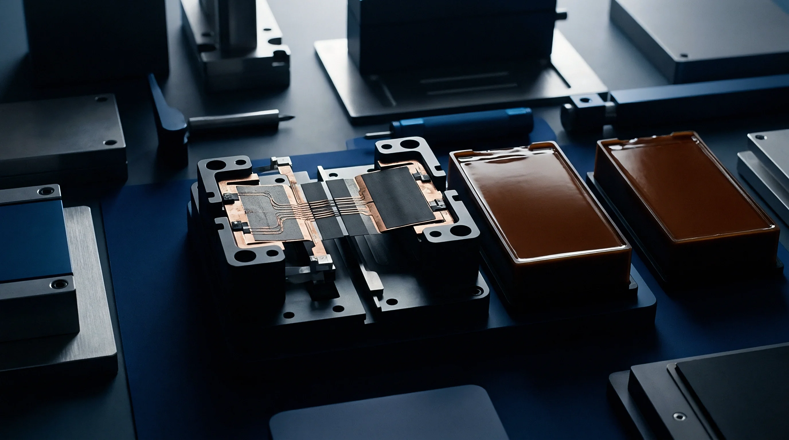

Threshold
Warranty agreements for industrial and automotive battery modules rely on clear physical thresholds to distinguish normal aging from operational abuse. Cell suppliers routinely deny claims when telemetry shows a module operated outside specified temperature or state of charge boundaries. Mechanical strain provides a key physical metric here, integrating lifetime duty cycle intensity, thermal stress, and overcharge history into a measurable dimensional state.
Strain thresholds map directly to remaining electrochemical capacity. As parasitic reactions consume active lithium, insoluble degradation products build up inside the anode pores. This solid mass buildup forces the cell structure outward permanently, making permanent mechanical deformation clear physical evidence of overall degradation.
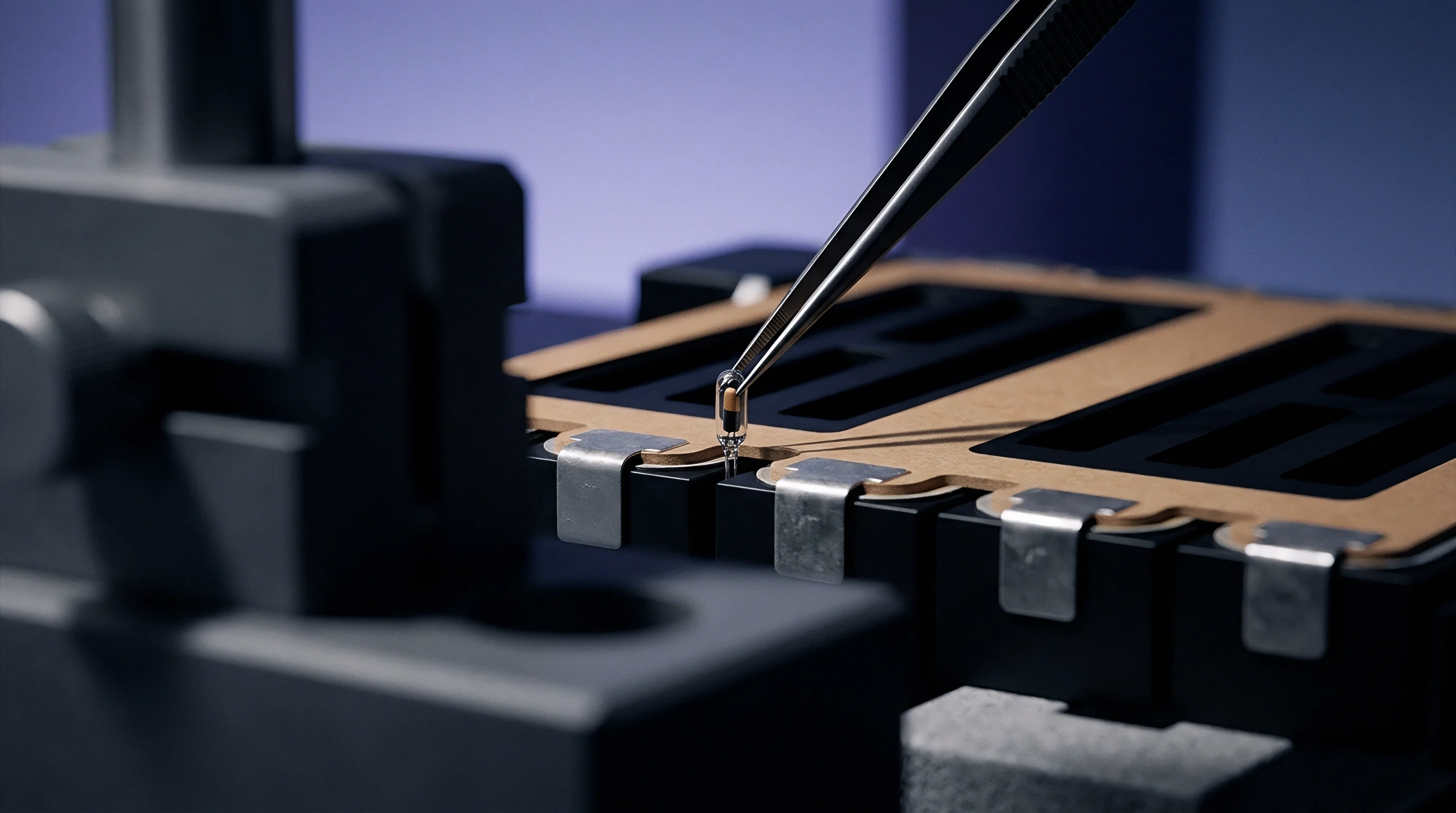
Which Module Load Conditions Breach Warranty Bounds?
Field installations monitor mechanical limits using placed sensors or periodic maintenance audits. Strain gauges mounted on tie rods convert tension elongation into continuous load telemetry. Miniature piezoresistive load cells positioned between the final end cell and the endplate track stack force dynamics in real time.
The battery management system flags an alert whenever sustained stack pressure crosses defined operational limits.
Dynamic stack pressures exceeding 1.5 MPa under high ambient temperatures void standard cell cycle-life guarantees.
Crossing designated mechanical limits causes specific forms of internal damage:
- Separator Pore Collapse occurs when localized compressive stress surpasses 2.0 MPa, choking lithium-ion transport pathways and elevating cell impedance.
- Anode Delamination initiates during rapid discharge if mechanical preload falls below 0.05 MPa, allowing active material flakes to detach from copper current collector foils.
- Weld Fatigue Fractures develop at ultrasonic terminal-to-busbar joints when cyclic module breathing displacement exceeds the shear endurance limit of the aluminum-copper interface.
- Vent Membrane Pre-Rupture happens when can sidewall deformation distorts the top cover assembly, altering the burst calibration of the safety pressure vent.
Operating strain is divided into three distinct zones. The green zone covers normal breathing up to 0.6 MPa, where full warranty coverage applies. The yellow zone spans 0.6 MPa to 1.2 MPa, representing accelerated aging where the supplier requires duty cycle auditing.
The red zone marks structural mechanical breach above 1.2 MPa, where warranty obligations terminate due to excessive mechanical stress.
Field data is still divided on whether brief dynamic shock loads cause the same long-term capacity fade as sustained static expansion pressures over months of continuous float charging.


Seam
Commercial contracts draw warranty boundaries right at the physical interface between the bare cell and the module enclosure. Cell suppliers guarantee capacity retention under strict environmental and electrical parameters ~ provided the module integrator maintains specified mechanical boundary conditions. If the module enclosure fails to maintain minimum stack pressure or exerts excessive constraint, the cell maker disclaims liability.
The warranty seam specifies these mechanical obligations for both parties.
Module integrators verify mechanical compliance by embedding sensor instrumentation during pilot builds. Sourcing agreements lay out incoming inspection protocols, audit criteria, and arbitration methods for resolving claims tied to mechanical degradation. When a pack loses capacity early, tear-down analysis in a calibrated lab reveals whether mechanical strain exceeded allowable baseline envelopes.
| Responsibility Domain | Cell Manufacturer Obligation | Module Integrator Obligation | Verification Artifact |
|---|---|---|---|
| Initial Dimensions | Deliver cells within ±0.25 mm envelope | Design fixture to absorb tolerance stack | First article inspection report |
| Preload Application | Specify min/max beginning of life pressure | Apply and verify 0.30 ± 0.05 MPa load | End of line force-displacement log |
| Breathing Allowance | Provide expansion coefficient per cycle | Incorporate compliant gap cushions | Cyclic thermal-mechanical test report |
| Pressure Containment | Ensure can integrity up to 1.5 MPa | Design endplates below 0.3 mm flex | Finite element analysis dossier |
| Telemetry Logging | Define critical threshold limits | Record load cell and temperature data | BMS non-volatile memory archive |
Contractual Enforcement Mechanics
Procurement teams secure warranty protection by inserting explicit strain baseline terms into commercial supply agreements. Clear language avoids disputes during root cause failure investigations, anchoring technical boundaries to defined physical parameters.
Standard warranty enforcement relies on precise contractual formulations:
The module integrator shall maintain stack compressive stress between 0.15 MPa and 1.20 MPa across all operational temperatures.
Supply contracts typically specify that capacity fade claims must include continuous pressure logs alongside voltage, current, and temperature datasets. If the integrator fails to capture mechanical strain telemetry, the supplier assumes structural boundary limits were breached, transferring financial responsibility for field replacements back to the integrator.