Isothermal Swelling Testing Protocols for Battery Pouch Cells
Isothermal swelling testing requires precise mechanical constraints and sub-degree temperature stability to isolate electrochemical cell growth from thermal drift.


Expansion
Electrochemical Drivers of Pouch Volume Change
Volume variations in pouch format lithium-ion cells stem from structural lattice shifts during phase transitions and continuous side reactions occurring at electrode interfaces. Graphitic anodes undergo distinct stage transitions during lithiation, expanding up to 10 percent along the c-axis as lithium ions intercalate between graphene sheets. Silicon oxide additives escalate this volumetric distortion, with pure silicon exhibiting isotropic expansion approaching 300 percent at full lithiation.
Cathode chemistries display inverse or complementary lattice behaviors: nickel-rich layered oxides shrink slightly along the c-axis at high state of charge due to increased electrostatic repulsion between oxygen layers, whereas lithium iron phosphate retains a near-constant olivine framework with total unit cell volume shifts under 7 percent.
Irreversible growth operates on a separate kinetic timeline, accumulating over operational lifecycles through solid electrolyte interphase continuous formation, electrolyte breakdown, and gas generation. Transition metal dissolution from high-voltage cathodes destabilizes the protective anode interphase, consuming active lithium and generating gaseous byproducts including ethylene, hydrogen, and carbon dioxide. In pouch configurations, the lack of rigid outer containment allows internal gas pockets to distend the aluminum-laminated foil pouch wall instantly, transforming local microscopic degradation into macro-level physical displacement.

Decoupling Reversible Breathing from Irreversible Degradation
Disentangling dynamic state-of-charge respiratory variations from long-term capacity fade requires precise alignment of current profiles with continuous displacement monitoring. Dynamic breathing tracks state of charge pseudo-linearly during early formation cycles, returning to baseline thickness upon discharge. As passive film growth proceeds, the minimum discharge thickness drifts upward, establishing an irreversible offset baseline.
| Anode Active Material | Cathode Active Material | Reversible Breathing Range (%) | Irreversible Growth at 1000 Cycles (%) | Dominant Gas Species |
|---|---|---|---|---|
| Artificial Graphite (100%) | NMC 811 | 3.5 to 5.2 | 4.0 to 6.5 | C2H4, CO2 |
| Graphite / SiO Composite (10 wt% SiO) | NMC 811 | 7.8 to 11.0 | 9.5 to 14.2 | H2, CH4, CO2 |
| Graphite / Si-C Composite (5 wt% Si) | NMC 622 | 5.0 to 7.5 | 6.2 to 8.8 | C2H4, H2 |
| Synthetic Graphite (100%) | LFP | 2.1 to 3.8 | 2.5 to 4.2 | CO, C2H4 |
Calculations ignoring the distinction between state-of-charge thickness variation and structural pouch growth lead directly to undersized module casing dimensions, causing structural deformation of end plates or premature cell venting when operating under tight mechanical constraint.

Platen

Boundary Mechanics and Stack Constraint Modes
Mechanical confinement during test routines dictates the internal stress field of the pouch cell stack. Testing unconstrained pouch cells inside ambient space produces unrepresentative gas pocketing, localized electrolyte starvation, and uneven current distribution across the electrode footprint. Applying controlled mechanical boundary conditions replicates the physical pressure environment of an engineered battery pack, driving uniform inter-electrode contact while suppressing localized swelling gradients.
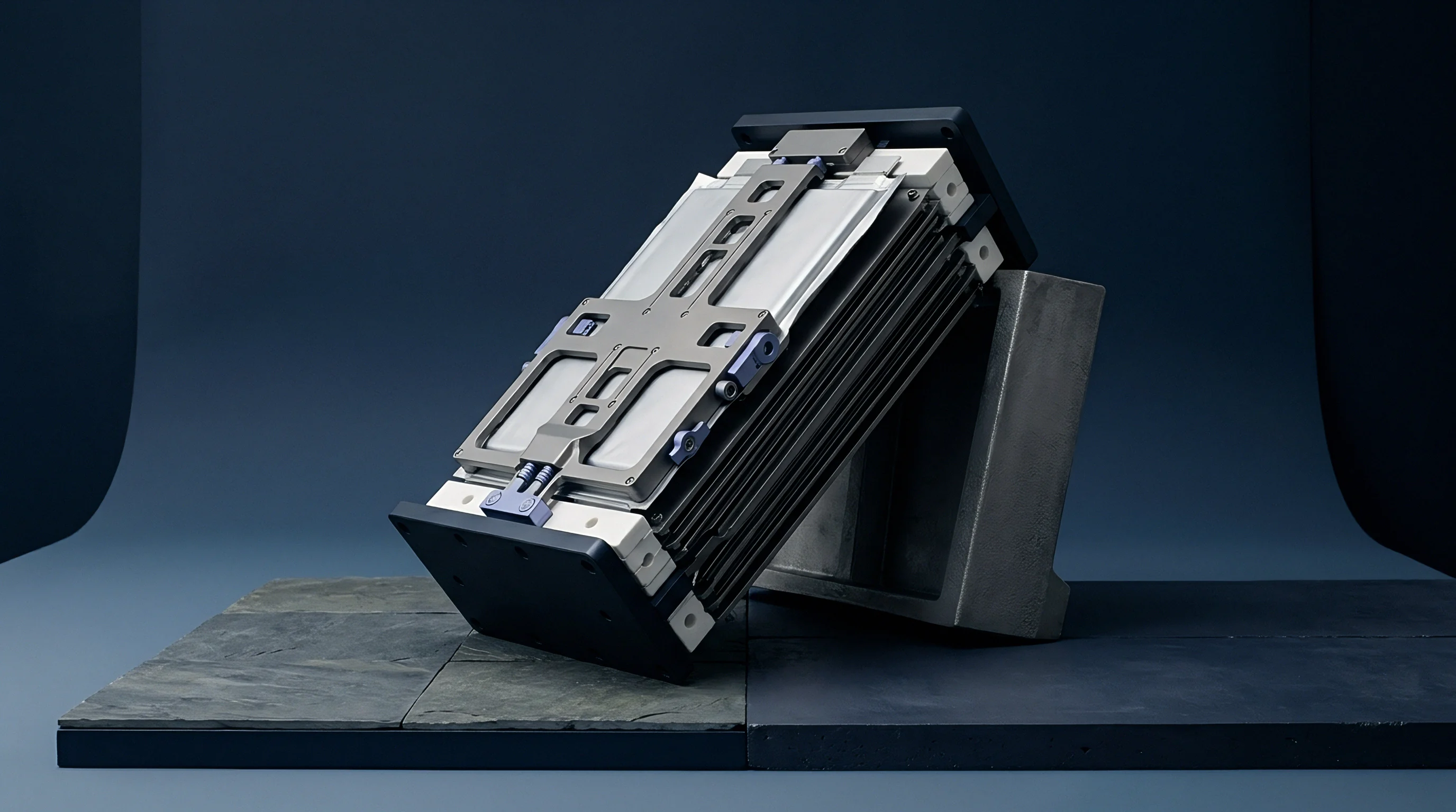
Two primary mechanical testing regimes dominate industrial characterization: constant volume and constant force. Constant volume fixtures clamp the pouch cell between rigid metallic plates set to a fixed gap distance, measuring internal stress accumulation through inline load cells as the cell expands during lithiation. Constant force fixtures employ calibrated spring packs, pneumatic actuators, or counterweighted leverage arms to maintain uniform pre-charge compression across the cell faces, recording linear thickness growth with displacement sensors.
Initial preload pressures between 0.05 MPa and 0.30 MPa stabilize internal pore structures without triggering separator deformation.

Fixture Geometry and Interface Compliances
Platen design specifies flat surfaces ground to flat tolerances within 0.02 millimeters across the entire contact surface to prevent false localized stress peaks. Steel or high-grade aluminum plates provide structural stiffness, preventing flexure under high stack forces. Thermally isolated platen designs integrate internal fluid channels or peltier heating elements, establishing direct thermal contact with the pouch face to eliminate thermal gradients across the cell body.
Inserting elastomeric pads or polyurethane foam cushions between the rigid platen face and the flexible pouch body smooths out manufacturing variations in cell thickness. Thin silicone sheets or conductive micro-cellular foams absorb small surface irregularities, ensuring uniform force delivery across seam edges and gas pockets without dampening structural displacement signals.
- Uncompensated Platen Flexure creates artificial pressure relief at the center of the cell, concentrating mechanical stress on the pouch periphery and accelerating edge-lamination tearing.
- Thermal Expansion Mismatch between metallic testing frames and sliding sensor rods introduces false displacement signals that obscure actual chemical cell swelling.
- Frictional Hysteresis in sliding guide pins distorts load cell readouts during constant-displacement relaxation phases, yielding false stress relaxation rates.
- Non-Parallel Alignment of upper and lower clamping surfaces induces shear forces across tab welds, resulting in internal collector tab fractures during volume changes.
According to standard engineering supply agreements, cell manufacturers accept compliance verification data only when testing protocols specify initial pre-charge stack pressures within 0.01 MPa tolerance using flat-ground platens maintained within 25 degrees Celsius +/- 0.5 degrees environment.


Soak
Isothermal Precision and Thermal Drift Elimination
Temperature fluctuations distort linear displacement metrics through thermal expansion of cell materials and test fixtures. Polyethylene and polypropylene separators, aluminum current collectors, and metallic platens carry positive coefficients of thermal expansion. A temperature drift of 3 degrees Celsius inside a thermal chamber can alter displacement measurements by an amount equivalent to several hundred cycles of electrochemical degradation.
Decoupling electrochemical swelling from simple volumetric expansion demands tight environmental temperature control. Forced-convection environmental chambers holding spatial uniformity within +/- 0.2 degrees Celsius across the active working zone eliminate boundary layer variations. Direct contact temperature sensors affixed to the tab leads and pouch center monitor heat generation during rapid charge and discharge pulses, providing real-time data to correct for internal thermal expansion.
| Substrate / Component | Material CTE (ppm/K) | Nominal Layer Thickness (mm) | Expansion per 1.0 K Temp Rise (μm) | Error Ratio vs 50 μm Swelling (%) |
|---|---|---|---|---|
| Aluminum Platen Set (Top/Bottom) | 23.0 | 40.00 | 0.920 | 1.84 |
| Cell Stack (50 double-side layers) | 55.0 (Composite) | 12.00 | 0.660 | 1.32 |
| Stainless Steel Sensor Pushrod | 16.0 | 150.00 | 2.400 | 4.80 |
| Fixturing Tie Rods (Steel) | 12.0 | 200.00 | 2.400 | 4.80 |

Conditioning Profiles and Equilibrating Mechanics
Commencing tests before internal temperature gradients dissipate ruins measurement accuracy. Pouch cells moved from ambient storage into an isothermal test chamber require a dedicated thermal conditioning soak. Larger pouch cells exceeding 60 Ah capacity possess substantial thermal mass, requiring extended rest periods to reach thermal equilibrium throughout their internal winding or stacking structure.
Thermal soak durations scaled to cell mass prevent core-to-surface temperature gradients from biasing initial thickness baselines.
Stabilization rules mandate holding the cell under passive clamp pressure at target temperature until tab and surface thermocouples match ambient chamber air temperature to within 0.1 degrees Celsius for a minimum of 60 consecutive minutes prior to applying initial electrical formation currents.

Metrology
Sensor Transducer Selection and Calibration Parameters
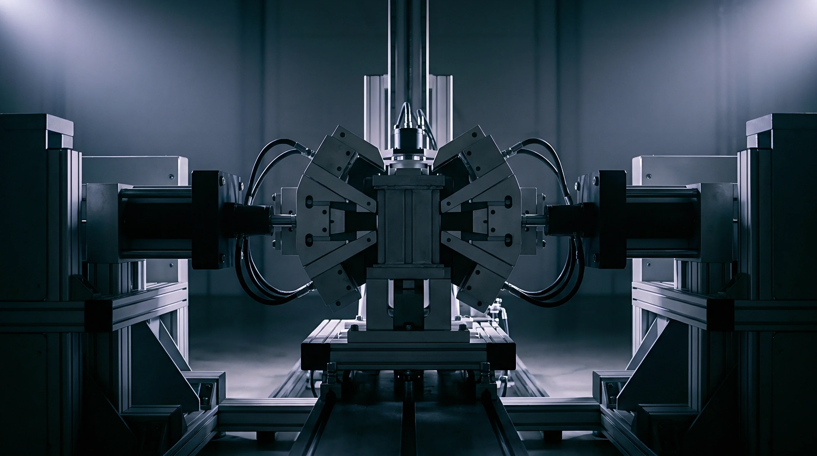
Quantifying sub-micron dimensional growth under varying mechanical loads requires choosing appropriate displacement transducers. Linear Variable Differential Transformers (LVDTs), optical laser displacement sensors, capacitive probes, and strain gauge load cells each present unique operational boundaries inside environmental chambers.
LVDTs operate via electromagnetic induction, delivering high resolution below 0.1 micrometers and long-term stability without physical wear. Their metallic cores require smooth mechanical contact with top platens through low-friction guide bearings to prevent side-loading errors. Laser triangulation sensors offer non-contact measurement, eliminating friction entirely; however, reflective changes on polished pouch surfaces or metallic fixtures can corrupt optical return signals unless matte-finish target plates are affixed to measurement points.
Displacement measuring sensors require calibration within environmental test chambers across full thermal ranges to zero out fixture expansion coefficients.
- Linear Variable Differential Transformers provide absolute position tracking with sub-micron resolution but require frictionless guidance systems to avoid applying uncalibrated point loads onto top platens.
- Strain Gauge Load Cells monitor stress development under rigid fixed-gap boundary conditions, requiring internal temperature compensation circuits to prevent bridge output drift.
- Capacitive Gap Sensors measure small displacement changes with high precision under high-frequency conditions but suffer sensitivity drops in high-humidity test environments.
- Multi-Point Tactile Matrices capture spatial swelling maps across large-format pouch surfaces, pinpointing internal gas pocket location during high-temperature storage regimes.
Spatial Mapping and Thickness Profiling Methods
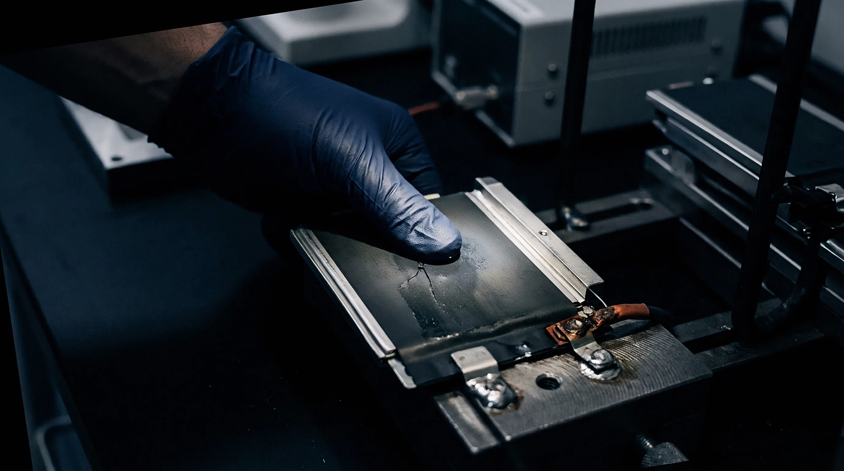
Single-point thickness measurements at the geometric center of a pouch cell often miss edge effects, seam distortion, and localized gas accumulation. Gas pockets tend to migrate toward the highest elevation or areas of lowest mechanical restraint, producing asymmetrical pouch distension.
Comprehensive metrology employs multi-axis sensor arrays or scanning laser profilers across the entire pouch footprint. Mapping nine distinct nodes across a grid reveals non-uniform volumetric growth caused by local current density variations, tab heating, or non-uniform electrode coating thickness. Averaging multi-point array data yields representative total volume growth metrics, preventing localized gas bubbles from skewing engineering decisions on module spacer thickness.
The vendor stated that minor dimensional creep on single-point sensors fell within standard production tolerances, omitting the fact that center-only probing overlooked a 1.2 millimeter edge expansion near the tab bridge.
Regime

How Does C Rate Acceleration Alter Swelling Profiles?
Accelerating test timelines by increasing charge and discharge C-rates alters the physical character of swelling metrics. High charging rates induce steep concentration gradients of lithium ions within anode particles, driving core-shell lattice strain that magnifies transient respiratory swelling beyond equilibrium values observed during slow C/20 testing. Excessive charge rates at low temperatures trigger lithium plating on graphitic surfaces, converting dissolved active lithium into metallic dendrites that form permanent, high-volume surface layers.
Isothermal swelling protocols establish explicit operating limits across state-of-charge windows, operating temperatures, and C-rates to ensure test data matches field duty cycles. Running continuous full-depth cycling between 0 percent and 100 percent state of charge accelerates structural electrode breakdown, whereas partial SOC cycling regimes isolate chemical gas evolution mechanisms associated with prolonged high-voltage exposure.
Worked Example: Lifetime Volumetric Expansion and Module Space Allocation
Evaluating module enclosure parameters for a 100 Ah automotive pouch cell illustrates the engineering application of isothermal swelling test data. Consider a pouch cell with initial nominal dimensions: length 350 mm, width 100 mm, thickness 12.00 mm (+/- 0.15 mm manufacturing tolerance). The module configuration arranges 12 pouch cells stacked face-to-face in series within a rigid aluminum frame bound by fixed end plates.
Baseline electrochemistry testing under isothermal conditions (25 degrees Celsius, 0.1 MPa initial stack pressure) yields the following empirical swelling coefficients:
Reversible Breathing Range: 4.2 percent of nominal thickness (0.504 mm per cell).
Irreversible Aging Growth Rate: 6.5 percent of nominal thickness at 80 percent State of Health (0.780 mm per cell).
Maximum Combined Swelling Peak per cell at end-of-life under 100 percent SOC condition: 0.504 mm + 0.780 mm = 1.284 mm per cell.
Calculating total stack expansion across 12 cells without compressible inter-cell spacers yields:
Total Stack Swelling = 12 cells x 1.284 mm = 15.408 mm total linear growth.
Adding cumulative manufacturing thickness tolerance stack-up (+/- 0.15 mm x 12 cells = +/- 1.80 mm) defines the total structural displacement budget requirement:
Maximum Design Displacement Space = 15.408 mm + 1.80 mm = 17.208 mm.
To avoid increasing module enclosure length by over 17 millimeters, elastomeric compression pads are inserted between adjacent cells. Selecting micro-cellular polyurethane foam with a non-linear stress-strain curve allows absorbing 1.284 mm of cell growth per pocket while increasing internal stack pressure from 0.10 MPa to 0.45 MPa at end-of-life.
Stress accumulation calculations confirm that maximum internal compression remains below the 0.60 MPa structural limit of separator pores, preventing separator collapse and internal short circuits.
- Mount the pre-conditioned pouch cell within the central alignment frame between top and bottom polished platens.
- Torque tie-rod assembly fasteners in a cross pattern until the load cell indicates target preload pressure of 0.10 MPa.
- Connect sensing instrumentation leads and zero all displacement transducers after a 30-minute thermal equilibrium hold.
- Initiate C/20 baseline charge-discharge cycle inside environmental chamber controlled at 25.0 degrees Celsius +/- 0.2 degrees.
- Record displacement and load cell channels synchronously at time intervals not exceeding 1.0 second.
- Execute accelerated life cycling profile while maintaining active cooling channels to keep tab surface temperature delta below 2.0 degrees.
What structural mechanism causes low-temperature charge swelling to persist after full discharge remains under active investigation within electrochemistry research teams.


Paperwork
Contractual Test Addenda and Boundary Definitions
Translating laboratory test results into enforceable cell purchase agreements requires establishing explicit test addenda in procurement contracts. Datasheets listing cell thickness as a single nominal figure without specifying stack pressure, temperature, state of charge, and measurement point location leave cell buyers exposed to warranty disputes when swollen cells deform pack enclosures.
Quality agreements must mandate specific test standard protocols such as ISO 12405 or UL 2580, modified by isothermal swelling provisions. Clauses must define precisely what constitutes acceptable swelling bounds at specified cycle markers, assigning financial liability for module redesigns or pack recalls if production lots exceed maximum volume thresholds during qualification testing.
| Specification Parameter | Standard Testing Target | Permissible Tolerance | Out-of-Spec Consequence |
|---|---|---|---|
| Initial Constraint Force | 0.10 MPa | +/- 0.005 MPa | Batch Rejection / Re-test |
| Chamber Temperature | 25.0 °C and 45.0 °C | +/- 0.3 °C | Invalidates Test Run |
| Reversible Expansion Limit | + 0.3% Max Shift | Cell Supplier Pays Tooling Mod | |
| End-of-Life Irreversible Limit | + 0.5% Max Shift | Warranty Claim / Lot Recall |
Incoming Inspection Lot Acceptance Protocols
Verifying incoming cell shipments involves implementing standardized sampling plans based on ISO 2859-1. Receiving inspections extract sample cells from production lots, placing them in rapid-screening swelling test fixtures under isothermal conditions for initial formation cycle verification.
Incorporating clear thermal and mechanical boundary definitions into supply contracts prevents suppliers from attributing swelling failures to buyer pack integration methods.
Failure to pass incoming swelling thresholds triggers immediate quarantine of the entire production lot. Standard quality provisions specify that three consecutive non-conforming lot receipts suspend supplier approval status, initiating formal failure analysis protocols to determine whether binder degradation, electrolyte contamination, or coating weight variations caused the abnormal volumetric expansion.