Quantifying Multi-Axis Dynamic Shear Transfer and Creep Thinning in Ultra-Thin Battery Separators
Dynamic shear transfer and compressive creep thin ultra-thin separators below five microns, increasing pinhole shorting risk and impedance under stack expansion.

Web
In high-energy lithium-ion cells, internal mechanical stress builds up during early processing ~ specifically roll-to-roll slitting, high-speed jellyroll winding, and z-fold pouch stacking. In ultra-thin microporous polyolefin separators measuring between 5 µm and 9 µm in thickness, these initial assembly tension fields interact with cyclic electrochemically induced volume changes during battery operation. Anode active materials expand and contract during lithiation and delithiation cycles.
Standard synthetic graphite exhibits volumetric breathing between 10% and 12%, while silicon-composite anodes expand beyond 300% locally. This cyclic motion drives multidirectional relative displacement right across the separator-electrode boundary.
Shear force transmission across this contact zone relies on complex tribological interactions. The local normal pressure field within a pouch or prismatic pack enclosure ranges from 0.3 MPa to 1.5 MPa under nominal pre-charge conditions, escalating to over 3.0 MPa at full state of charge as electrode swelling compresses the internal stack against rigid cell walls. Under these compressive loads, microscopic surface asperities on the active material coating sink into the softer polymeric surface of the microporous membrane.
Dynamic vehicle vibration, planar thermal expansion gradients, and differential swelling between adjacent electrode sheets continuously convert normal compression into multi-axis in-plane shear acting simultaneously along the Machine Direction and Transverse Direction.

Interfacial Friction and Kinematic Displacement
Frictional engagement between electrode coatings and polymeric substrates depends heavily on surface micro-roughness. Uncoated wet-process polyethylene membranes show a dry static friction coefficient of 0.25 to 0.35 when placed in contact with calendered graphite anodes. Applying ceramic nanoparticle coatings such as alpha-alumina or boehmite with average particle sizes ranging from 200 nm to 800 nm increases this static coefficient to 0.45 ~ 0.65.
Higher friction coefficients enhance mechanical engagement, limiting macro-scale sliding between layers during shock events. However, this interlocking forces in-plane shear stresses directly into the thin polymer matrix rather than allowing interfacial slip.
Liquid organic carbonate electrolytes containing lithium hexafluorophosphate act as boundary lubricants inside the cell stack. Ethylene carbonate, ethyl methyl carbonate, and dimethyl carbonate mixtures wet both the porous polyolefin structure and the particulate electrode matrix, altering local shear stress transmission. Absorbed electrolyte plasticizes the semi-crystalline polyethylene, dropping its shear yield strength.
Under dynamic lateral vibrations matching automotive road profile frequencies between 10 Hz and 200 Hz, stick-slip frictional behavior develops at the electrode contact boundaries. Microscopic slip cycles generate localized frictional heating and cyclic lateral strain, driving structural rearrangement of the polyolefin fibrils surrounding the pore channels.
Dynamic shear transfer at the separator surface forces structural deformation into the polymer bulk when interfacial friction exceeds the yield limit of the microporous membrane.
Micro-mechanical shear transfer occurs through distinct physical mechanisms across the electrode interface:
- Asperity Interlocking Force transfer occurs where localized electrode coating peaks sink into the softer polymeric substrate, converting planar movement directly into internal mechanical deformation.
- Hydrodynamic Fluid Shear within electrolyte-filled pore channels generates viscous resistance during high-frequency micro-displacements, creating localized internal hydraulic pressure gradients.
- Adhesive Friction Drag along the ceramic nanoparticle binder layer distributes planar shear forces across the surface, transferring structural stress from active material expansion into the separator core.
- Stick Slip Surface Instability causes periodic energy storage and release during micro-sliding cycles, generating high-frequency cyclic stress spikes along the polymer fibril nodes.

Biaxial Shear Vectors in High Energy Cell Architectures
Planar strain tensors measured across prismatic and large-format pouch separators reveal uneven vector distributions. Along the Machine Direction, residual tension from primary extrusion and orientation processing remains stored within the polymer backbone. Transverse Direction stresses arise predominantly from thermal expansion mismatch and non-uniform lithium insertion along electrode edges.
When these orthogonal stress components combine with out-of-plane normal compression, a fully coupled three-dimensional stress tensor acts upon the ultra-thin polyolefin film. The resulting effective shear stress calculated through the von Mises yield criterion frequently exceeds the localized yield strength of sub-seven micron membranes at elevated pack operating temperatures.
| Separator Architecture | Nominal Thickness (µm) | Dry Friction Coeff. (Anode) | Wetted Friction Coeff. (EC/EMC) | Interfacial Shear Strength (MPa) | Transverse Yield Vector (MPa) |
|---|---|---|---|---|---|
| Wet PE Monolayer | 5.0 ± 0.3 | 0.28 | 0.18 | 2.4 | 14.2 |
| Wet PE with Ceramic (Single-Side) | 7.0 ± 0.4 | 0.52 | 0.34 | 4.1 | 18.6 |
| Dry PP/PE/PP Trilayer | 9.0 ± 0.5 | 0.31 | 0.22 | 3.1 | 22.5 |
| Wet PE with Ceramic & PVDF (Dual-Side) | 9.0 ± 0.4 | 0.61 | 0.41 | 5.8 | 17.8 |
Edge constraint conditions inside rigid prismatic cans concentrate shear stress along the cell perimeter. Minor width variations between active material coatings and the separator roll create step-change boundary conditions along the trimmed edges. Under cyclic stack swelling, the separator experiences severe bending and shear stress concentrations precisely at these electrode edge steps.
Over repeated charge cycles, local shear strains exceed 8%, causing permanent plastic stretching of the edge material, localized pore collapse, and reduced cross-web tension uniformity. Slitting burrs present on copper anode current collectors act as mechanical stress risers, concentrating multiaxial shear vectors directly onto the thin polyolefin film.
Separators in cylindrical 21700 and 4680 formats endure distinct shear patterns driven by radial expansion against immovable outer steel walls. As the central core of the jellyroll expands outward during lithiation, inner separator wraps undergo severe circumferential tension coupled with radial compression. This force state generates high shear stresses along the spiral plane of the winding.
Ultra-thin 5 µm separators operating in high-nickel cylindrical designs exhibit significant machine-direction elongation under this constraint, leading to progressive cross-sectional thinning over prolonged field cycling.
Field delamination and localized edge wrinkling stem either from aggressive pack-level assembly clamping parameters or from intrinsic mechanical anisotropy within the polyolefin web.
Strain
Viscoelastic deformation in microporous semi-crystalline polyolefins depends heavily on temperature, time, and multiaxial stress magnitudes. Polyethylene features a glass transition temperature near -120°C and a crystalline melting point around 135°C. At normal battery operating environments spanning 25°C to 60°C, high-density polyethylene operates well within its rubbery viscoelastic plateau. Under constant stack compression from pack enclosure plates and active material expansion, the polymer chains undergo continuous creep deformation, causing thickness reduction and pore space collapse over time.
Polymer creep in ultra-thin battery separators manifests through three distinct phases: primary transient creep characterized by a rapidly decreasing strain rate, secondary steady-state creep governed by linear viscous flow, and tertiary creep marked by localized mechanical necking and micro-void coalescence leading to structural failure. In sub-seven micron wet-process membranes, steady-state compressive creep dominates cell lifetime aging. The rate of thickness reduction follows an Arrhenius dependency, accelerating by a factor of 2.4 for every 10°C increase in continuous operating temperature under a baseline compressive stress of 1.0 MPa.

Compressive Creep Rate and Viscoelastic Relaxation
Mathematical modeling of separator creep thinning utilizes a four-element Burgers viscoelastic framework comprising Maxwell and Kelvin-Voigt elements connected in series. The instantaneous elastic response J0 accounts for initial thickness loss upon mechanical cell clamping. The viscoelastic retardation phase, defined by compliance J1 and relaxation time τ, captures time-dependent polymer chain disentanglement over initial formation cycling.
Long-term thinning kinetics depend primarily on the linear viscous flow parameter η0, which dictates permanent plastic deformation across thousands of operating hours.
A 7 µm wet-process polyethylene separator subjected to 1.2 MPa continuous stack pressure at 55°C loses 18% of its initial thickness within 1,000 hours, decreasing total pore volume from 42% down to 29%.
Dynamic Mechanical Thermal Analysis reveals distinct viscoelastic transitions under simultaneous shear and compressive modes. Storage modulus E’ drops sharply as temperature rises from 25°C to 60°C, falling from approximately 450 MPa down to less than 160 MPa in unoriented wet-process polyethylene films. Loss modulus E” reaches a peak within this temperature window, signifying elevated mechanical damping and internal molecular friction during dynamic load cycles.
When multi-axis dynamic shear loads superimpose over static compression, the effective creep rate increases up to 35% compared to static loading alone, a phenomenon known as dynamic stress-assisted relaxation.
Polymer morphology dictates resistance to viscoelastic compression under load:
- High Molecular Weight Polyethylene provides dense molecular chain entanglements that resist long-term viscous flow and suppress creep rate at elevated pack operating temperatures.
- Bi-Axial Orientation Ratio aligns crystalline lamellae in orthogonal directions, enhancing planar yield strength while distributing compressive loads evenly across the pore wall network.
- Ceramic Nanoparticle Reinforcement forms a rigid inorganic skeleton across the polymer surface, sharing normal compressive loads and retarding bulk polymer creep deformation.
- Cross-Linked Polymer Networks introduce permanent chemical cross-links that suppress long-term chain slip and eliminate tertiary creep acceleration under thermal stress.

Porosity Decay under Continuous Stack Pressure
Loss of pore volume directly degrades electrochemical transport across the electrolyte-filled separator. Microporous membranes rely on interconnected open-cell pore networks to facilitate lithium-ion transport between positive and negative electrodes. As compressive creep compresses the polymer backbone in the z-axis, individual pore walls buckle into open pore cavities.
This reduction in overall porosity (ε) causes a non-linear increase in tortuosity (τ), severely restricting ionic conductive paths within the liquid electrolyte phase.
| Polymer Base Chemistry | Initial Thickness (µm) | Storage Modulus at 55°C (MPa) | Creep Thinning Rate at 1.0 MPa (%/1000h) | Initial Porosity (%) | Aged Porosity at 1000h (%) |
|---|---|---|---|---|---|
| Wet Ultra-High MWPE | 5.2 ± 0.2 | 210 | 14.5 | 41.5 | 31.2 |
| Wet Standard PE | 5.0 ± 0.3 | 145 | 22.8 | 43.0 | 28.4 |
| Dry PP Monolayer | 7.1 ± 0.3 | 380 | 8.2 | 38.5 | 33.8 |
| Dry PP/PE/PP Trilayer | 8.8 ± 0.4 | 295 | 11.4 | 39.0 | 32.1 |
| Ceramic Coated PE (Al2O3) | 7.0 ± 0.3 | 310 | 9.6 | 42.0 | 36.5 |
The MacMullin number (NM), defined as the ratio of electrolyte-filled separator resistivity to pure electrolyte resistivity, quantifies ionic transport impedance. Thinning reduces physical path length d, which theoretically lowers resistance, but simultaneous porosity collapse and tortuosity elevation dominate the relationship. MacMullin number scales inversely with porosity raised to the Archie exponent (p ≈ 1.5 – 2.0), yielding NM = τ2 / ε.
A separator experiencing a 20% reduction in thickness alongside a 35% loss in open porosity exhibits an overall MacMullin number escalation from 4.2 up to 8.7, effectively doubling ionic transport resistance across the membrane.
Local current density distributions become highly inhomogeneous as pore networks collapse non-uniformly across the separator surface. Regions subjected to elevated localized compression, such as cathode particle contact points or electrode edge steps, undergo localized pore closure. Ions divert around these high-resistance zones, creating current density hot spots in adjacent porous regions.
Local current density spikes accelerate lithium plating during fast-charging operations, establishing thermal and electrochemical degradation modes within the cell stack.
Sub-seven micron polyolefin films operating under 1.5 MPa stack pressure at 60°C approach a physical limit where creep-induced pore closure permanently impairs rate capability. The critical question remains whether molecular cross-linking techniques can successfully freeze viscoelastic creep deformation without compromising thermal shutdown functionality during catastrophic fault events.

Bench
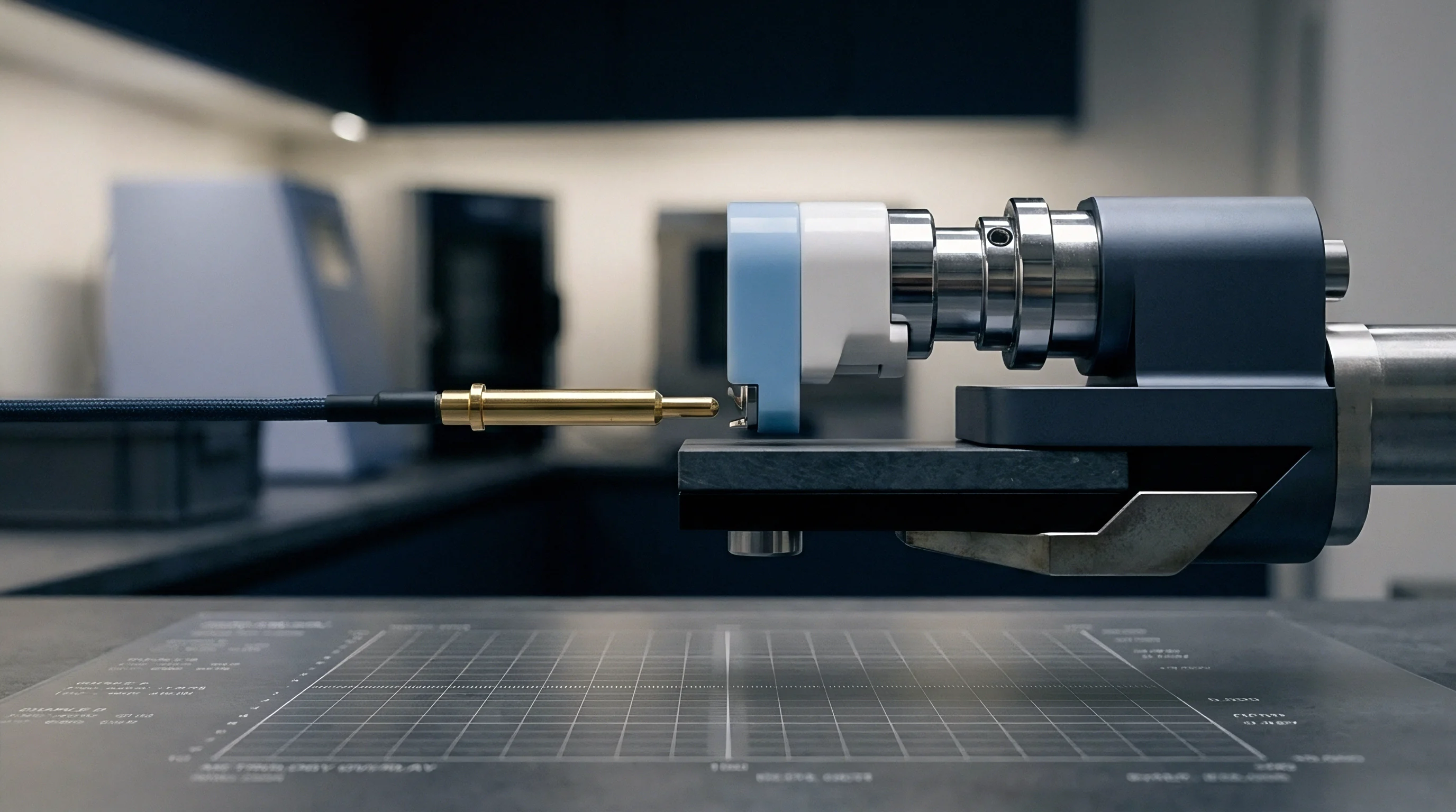
Quantifying multi-axis dynamic shear transfer and long-term creep thinning requires high-precision mechanical test fixtures integrated with real-time environmental controls. Traditional tensile testers and standardized puncture test rigs fail to replicate the complex coupled stress fields present inside operating battery packs. Advanced testing systems apply controlled normal compressive loads while simultaneously imposing cyclic in-plane lateral displacements, simulating the exact mechanical coupling experienced by separators clamped between swelling electrode sheets under vehicle vibration profiles.
Biaxial shear characterization relies on custom tribology fixtures mounted within thermal chambers capable of regulating temperature from -40°C to 100°C and relative humidity up to 90%. Precision piezo-actuators enforce micro-step lateral motions down to 0.1 µm resolution across frequencies ranging from 0.01 Hz to 100 Hz. Load cells simultaneously measure normal compressive force (Fz), machine-direction shear force (Fx), and transverse-direction shear force (Fy). Electrically insulated test platens equipped with high-frequency electrochemical impedance spectroscopy enable real-time monitoring of ionic resistance shifts as shear deformation progresses.
Does Biaxial Dynamic Load Accelerate Localized Separator Thinning?
Superimposing dynamic lateral shear over continuous normal compression accelerates the rate of local polymer thinning compared to pure static loading conditions. Microscopic surface sliding generates shear traction vectors that lower the effective compressive yield stress of the semi-crystalline polyolefin film. Under cyclic shear displacement of ±100 µm at a frequency of 2.0 Hz and a static normal pressure of 1.0 MPa, separators exhibit a 40% faster rate of thickness decay during the initial 100 hours of testing compared to baseline static creep controls.
ASTM D5264 modified dynamic tribology tests verify that wetted ceramic-coated separators maintain higher interfacial shear stability than uncoated membranes under continuous multi-axis vibration.
Accurate experimental measurement of dynamic shear transfer and creep thinning follows a precise, sequential procedure:
- Mount the target separator specimen into the biaxial mechanical test cell using vacuum-assisted alignment fixtures to eliminate initial wrinkles or pre-strain gradients across the measuring area.
- Infiltrate the test chamber with baseline battery electrolyte under an argon atmosphere, ensuring complete chemical wetting of the porous polymer matrix for 30 minutes prior to applying mechanical loads.
- Apply a baseline normal compressive stress of 0.5 MPa using a closed-loop electromechanical actuator, allowing the film to settle into initial elastic contact equilibrium.
- Initiate sinusoidal lateral shear oscillations along the Machine Direction at a defined displacement amplitude of ±50 µm and a frequency of 1.0 Hz while maintaining constant ambient chamber temperature at 45°C.
- Superimpose secondary Transverse Direction shear oscillations at a orthogonal frequency of 1.5 Hz to generate a fully coupled planar Lissajous shear displacement pattern across the specimen surface.
- Record real-time continuous z-axis thickness decay using high-speed optical laser displacement sensors accurate to 20 nm resolution throughout the 500-hour test execution window.
- Perform continuous high-frequency 10 kHz AC impedance sweeps across the platen electrodes to track instantaneous ionic resistance changes resulting from progressive pore collapse.
- Halt test execution, extract the deformed film under dry conditions, and perform cross-sectional Scanning Electron Microscopy to quantify localized pore deformation, fibril stretching, and ceramic layer delamination.
Dynamic Mechanical Thermal Analysis and Friction Metrology
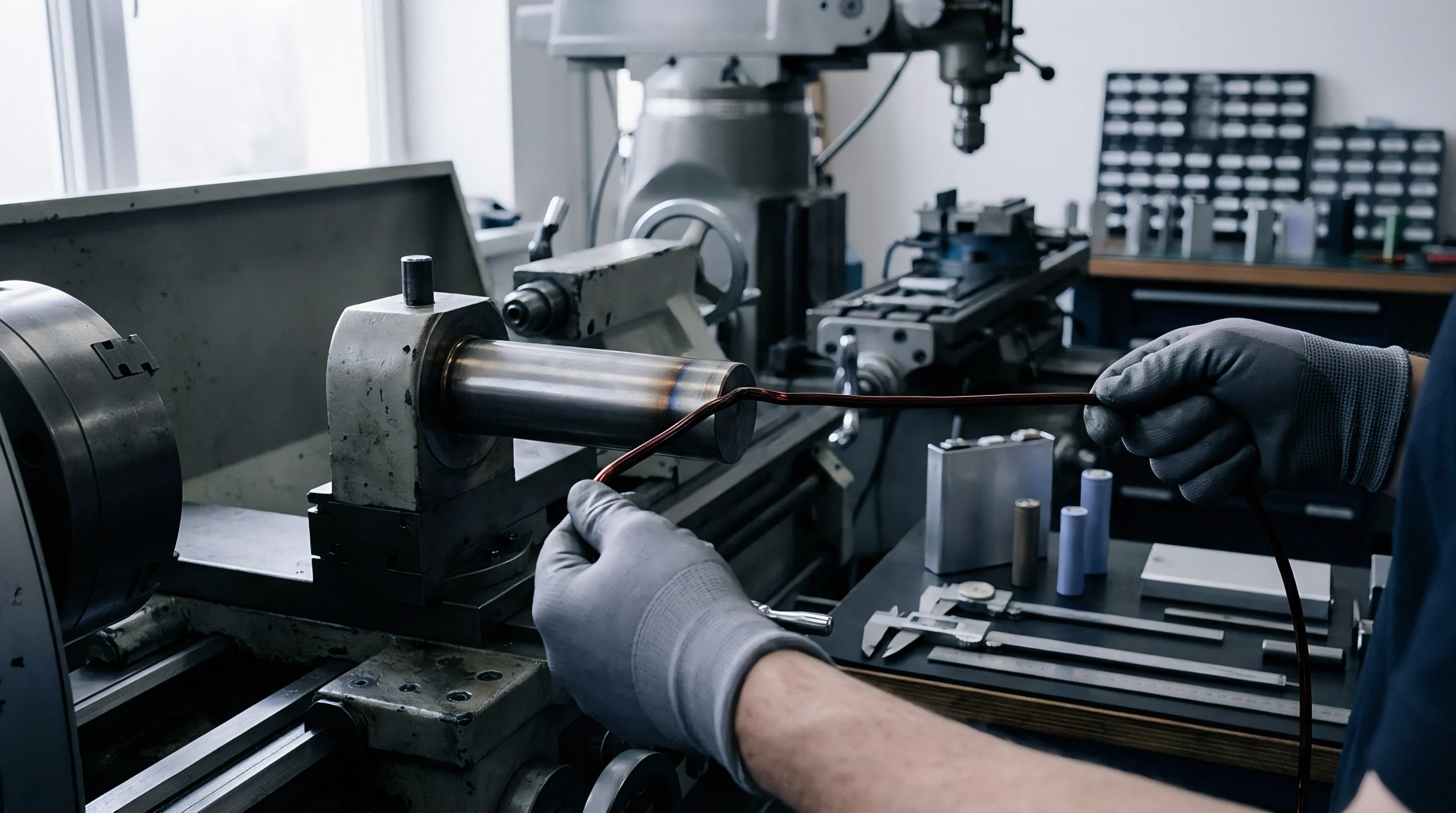
Dynamic Mechanical Thermal Analysis provides critical temperature-dependent viscoelastic profiles of ultra-thin membranes under controlled atmospheric conditions. Measuring complex modulus components (E = E’ + iE”) across a temperature range from -50°C to 120°C under varying sweep frequencies establishes master curves via the Time-Temperature Superposition principle. These shift factors allow engineers to predict multi-year compressive creep thinning kinetics from accelerated high-temperature short-duration laboratory test data.
| Sample Identification | Test Normal Stress (MPa) | Shear Amplitude / Freq. (µm / Hz) | Test Temp (°C) | Thickness Decay at 500h (%) | Impedance Growth ΔR (%) |
|---|---|---|---|---|---|
| 5 µm Wet PE (Uncoated) | 0.8 | ±50 / 1.0 | 25 | 8.4 | +14.2 |
| 5 µm Wet PE (Uncoated) | 0.8 | ±50 / 1.0 | 55 | 21.6 | +48.5 |
| 5 µm Wet PE (Uncoated) | 1.5 | ±100 / 2.5 | 55 | 34.2 | +112.0 |
| 7 µm Ceramic Coated PE | 0.8 | ±50 / 1.0 | 55 | 9.8 | +18.1 |
| 7 µm Ceramic Coated PE | 1.5 | ±100 / 2.5 | 55 | 16.5 | +35.4 |
| 9 µm Trilayer PP/PE/PP | 1.5 | ±100 / 2.5 | 55 | 12.1 | +24.8 |
Surface friction metrology under wetted conditions relies on modified pin-on-flat and flat-on-flat sliding configurations. The dynamic friction response exhibits strong dependence on sliding velocity, normal force, and electrolyte temperature. At low sliding velocities below 0.01 mm/s, boundary lubrication regimes dominate, where active material particles directly contact the polymer substrate.
At higher sliding velocities, partial elastohydrodynamic fluid film formation occurs within the electrolyte-wetted interface, temporarily reducing the dynamic friction coefficient while increasing local fluid shear stresses.
Evaluating separator mechanics without accounting for coupled dynamic lateral shear during compressive thermal aging leads directly to underestimating thickness loss. That oversight shows up later as unexpected high-frequency impedance spikes and premature battery pack degradation in high-vibration automotive applications.


Ledger
Creep thinning and multi-axis shear damage directly threaten the long-term electrochemical safety and reliability of ultra-thin battery separators. Thickness loss reduces the physical separation distance between anode and cathode current collectors, lowering the dielectric breakdown voltage threshold of the electrolyte-impregnated membrane. When localized compressive creep reduces a 5 µm separator down to less than 2.5 µm at particle contact points, the local electric field intensity increases proportionally, elevating the probability of dielectric breakdown and localized micro-shorting.
Internal resistance growth serves as an early indicator of severe separator creep degradation. As continuous stack compression collapses the open pore network, ionic conductivity drops, driving up the bulk ohmic resistance (RΩ) and charge transfer impedance (Rct) of the cell. Higher internal resistance accelerates Joule heating during heavy power discharge pulses, creating a positive feedback loop: elevated temperatures accelerate polyolefin creep rates, further closing pores, increasing resistance, and generating higher heat loads during subsequent operation.

Impedance Growth and Ionic Transport Bottlenecks
Electrochemical Impedance Spectroscopy reveals distinct spectral signatures corresponding to separator structural collapse. In a standard Nyquist plot, high-frequency intercept shifts rightward along the real axis (Z’), directly measuring the loss of liquid electrolyte mobility within the compressed pore space. Simultaneously, the semi-circle representing solid-electrolyte interphase and charge transfer resistance expands due to non-uniform current distribution over the partially blocked electrode surface.
Sand’s time calculations dictate the operational boundaries for high-rate fast charging before metallic lithium deposition initiates at the anode surface:
τs = π D left( fraczc e C02 J (1 – t+) right)2
Where D represents the ambipolar diffusion coefficient, C0 is initial salt concentration, J is local current density, and t+ is the lithium transference number. Creep thinning concentrates current flow into remaining high-porosity micro-zones, raising local current density J by factors of two to four. Because Sand’s time scales inversely with the square of current density (J-2), localized separator thinning reduces the permissible fast-charging duration prior to lithium dendrite nucleation by over 75% at compressed sites.

Dendrite Penetration Risk in Creep Thinning Domains
Lithium dendrite growth accelerates rapidly in regions where separator creep thinning creates localized compressive stress concentrations. Growing dendrites exert mechanical tip pressures exceeding 15 MPa against the separator surface. While fully dense ceramics withstand these forces, ultra-thin polyolefin films undergo plastic yield and physical puncture under localized dendrite pressure, especially when elevated temperatures soften the polymer backbone.
Puncture leads directly to hard internal short circuits, sudden voltage drops, and potential thermal runaway events.
Rigorous RFQ engineering schedules incorporate strict mechanical acceptance bounds to mitigate field failures:
- Maximum Permissible Creep Thinning Rate shall not exceed 12% total initial thickness loss after 1,000 hours under 1.0 MPa static compression at 55°C per ISO 11546 creep metrology.
- Retained Air Permeability Limit mandates that Gurley values shall not exceed 250 s/100 mL following 15% enforced mechanical thickness reduction.
- Ceramic Layer Delamination Resistance requires zero particle shedding under multi-axis dynamic shear testing at 2.0 MPa combined normal pressure per ASTM D5264.
- Dielectric Breakdown Voltage Floor specifies minimum dielectric strength of 1.2 kV/mm in fully electrolyte-wetted condition following 500 hours of cyclic thermal-mechanical conditioning.
- Puncture Resistance Threshold demands minimum 350 grams force (3.43 N) using a 1.0 mm radius spherical probe per ASTM D3763 standards on aged membranes.
Supply agreements incorporating UN 38.3 transport testing and IEC 62133 compliance clauses require cell manufacturers to demonstrate that separator creep thinning under maximum pack enclosure pressure does not trigger internal short circuits during combined thermal shock and vibration profiles.

Transit
Integrating ultra-thin battery separators into commercial pack assemblies requires balancing mechanical constraint requirements against thermal, electrical, and landed-cost objectives. Structural battery pack architectures utilize rigid aluminum enclosures or composite top covers to apply uniform baseline clamping force across pouch and prismatic cell stacks. Selecting ideal compression pad materials, such as microcellular polyurethane foams or silicone sponges, maintains optimal stack pressure within a defined window between 0.2 MPa (preventing interfacial delamination) and 0.8 MPa (suppressing long-term separator creep thinning).
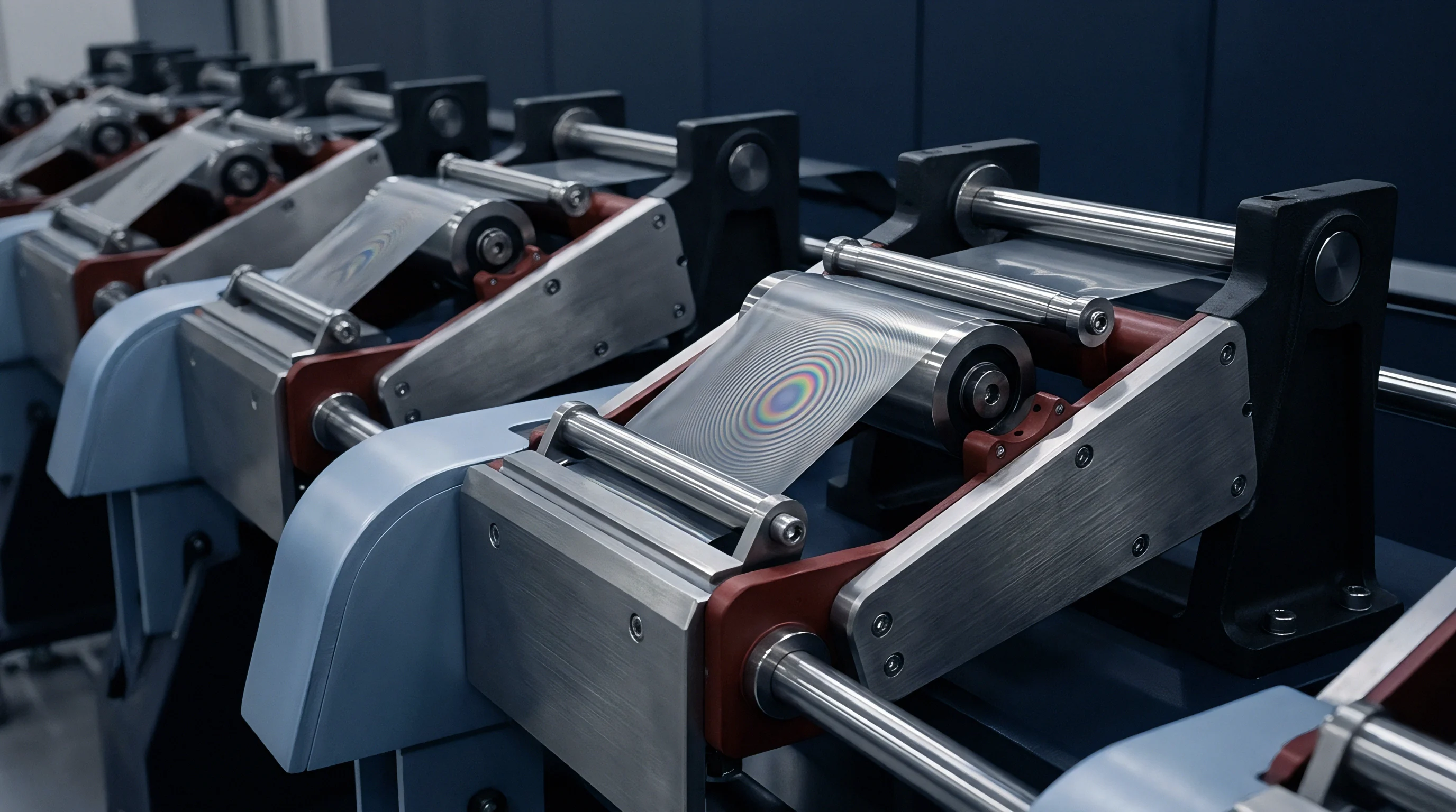
Tooling investments for ultra-thin separator handling on high-speed NPI production lines represent major capital expenditures. Roll-to-roll unwinding systems, automatic web tension control load cells, and non-contact ultrasonic slitting heads require sub-millimeter positioning accuracy to prevent web tearing, edge fraying, or static-induced wrinkling of 5 µm films. Line speeds exceeding 1.5 meters per second generate aerodynamic boundary layers that flap thin separator webs, requiring active vacuum guidance plates to preserve web alignment during high-speed cell assembly.
Stack Pressure Regulation and Enclosure Mechanics
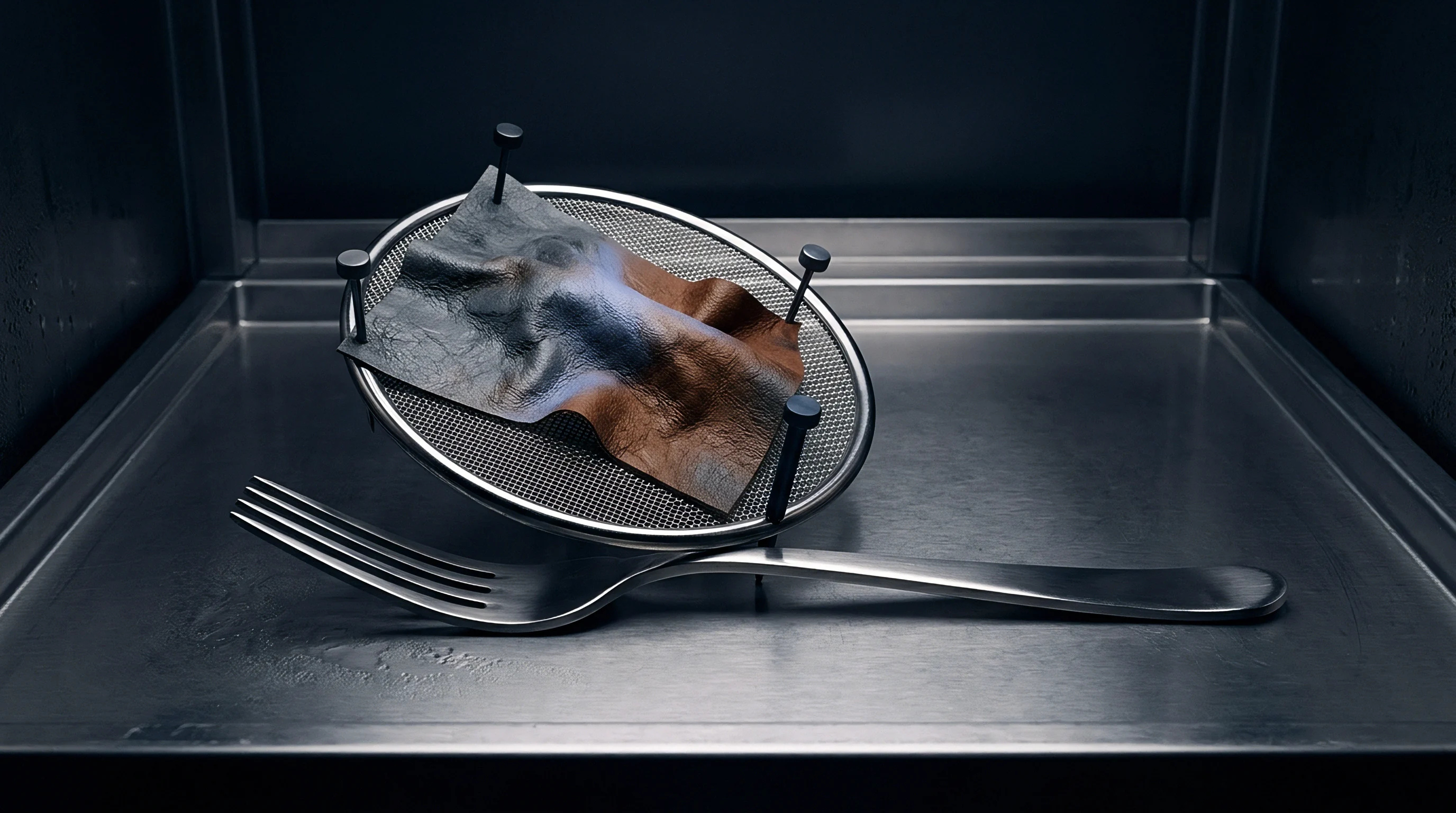
Cell swelling compensation strategies rely on non-linear foam spring curves to absorb cathode and anode volumetric expansion across thousands of operational charge cycles. As active material swelling increases overall cell thickness, the compressed pad stiffness (kpad) rises sharply. If pad stiffness is specified too high, internal stack pressure rapidly climbs past 2.5 MPa at full state of charge, accelerating separator creep thinning, pore collapse, and impedance growth.
Conversely, overly compliant pads fail to provide sufficient restraint during discharge, allowing electrode layers to delaminate and create gas pocket voids.
| Cell Format Choice | Separator Thickness Choice (µm) | Tooling NRE Impact ($ USD) | Stack Pressure Window (MPa) | BMS Scope & Voltage Boundary | Compliance Ownership Seam |
|---|---|---|---|---|---|
| Large Pouch Cell (100 Ah) | 5.0 (Wet PE + Ceramic) | 450,000 | 0.3 – 0.7 | Cell-level temperature & strain compensation | Pack Integrator owns expansion foam tuning |
| Rigid Prismatic Cell (150 Ah) | 7.0 (Wet PE Dual Ceramic) | 620,000 | 0.4 – 1.2 | Module-level pressure monitoring feedback | Cell Maker guarantees internal wrap tension |
| Cylindrical 4680 Cell | 9.0 (Dry Trilayer PP/PE) | 850,000 | 0.8 – 2.5 (Radial) | String-level current interrupt protection | Cell Maker owns jellyroll core expansion file |
Landed cost trade-offs depend on balancing separator thickness selection against overall volumetric energy density gains and cell scrap rates during line bring-up. Transitioning from a standard 9 µm separator down to a 5 µm ultra-thin film yields a 3.2% increase in volumetric energy density at the cell level, reducing cathode and anode current collector length requirements for a targeted Ah capacity. Line scrap rates during initial pilot winding runs typically rise from 1.5% up to 4.8% due to increased web handling sensitivity, requiring precise tension control adjustments to recoup NRE investment.
Designing compression pads with non-linear spring rates absorbs active material expansion without exceeding the critical creep threshold of ultra-thin polyolefin membranes.
Commercial Ownership and Warranty Boundary Allocation
Establishing clear commercial responsibility boundaries between cell suppliers, pack assembly houses, and vehicle manufacturers requires precise technical specifications within purchasing contracts. Separator mechanical failure modes under multi-axis dynamic shear frequently trigger warranty disputes when performance boundaries are left ambiguous. Defining explicit test standards, inspection frequencies, and acceptable dimensional tolerance limits in the master supply agreement ensures unambiguous liability assignment in the event of field quality returns.
In warranty claims originating from field-aged battery packs, disputes routinely hinge on whether capacity fade resulted from intrinsic chemical aging or mechanical pore closure driven by excessive external pack clamping pressure. Standardized RFQ schedules assign mechanical compliance ownership based on format boundaries: cell manufacturers hold sole responsibility for internal jellyroll tension control and initial separator integrity, while pack integrators own the long-term stack pressure evolution governed by enclosure pad selection and structural tie-rod thermal expansion matching.
A safe rule of thumb dictates matching separator ceramic coating thickness directly to maximum expected active material expansion force, ensuring hard inorganic particles support stack compression before polyolefin creep initiates.