Mechanical Preload Optimization in Structural Battery Pack Assemblies
Optimizing battery preload requires balancing compliant cushions and chassis stiffness to hold cell pressure between 0.10 MPa and 1.0 MPa across full lifecycle.
Clamp
Prismatic lithium-ion cells require sustained mechanical restraint to survive commercial lifecycle targets. Left unconstrained, a lithium iron phosphate or nickel-manganese-cobalt cell thickens continuously through cycling. Part of that expansion is reversible ~ the crystal lattices dilate and contract as lithium shuttles in and out ~ while the rest is permanent, driven by solid electrolyte interphase accumulation, gas generation, and particle microcracking.
In structural packs, the cell chassis must also shoulder road vibration, vehicle torsion, and crash forces as a shear element. Setting the beginning-of-life boundary pressure is therefore a balancing act between capacity retention, impedance growth, and structural mass.
Maintaining a steady preload suppresses active material delamination and retards the formation of dead lithium domains. Cell manufacturers typically prescribe 0.10 MPa to 0.30 MPa at 30 percent state of charge for initial installation. If the assembly fails to provide that baseline, gaps open at the electrode-separator interface.
Those contact losses skew local current density, precipitating lithium plating during fast charging. On the other end, excessive clamp loads ~ above 0.60 MPa initially or 1.20 MPa by end of life ~ pinch the porous separator, lowering ionic conductivity and risking shear punctures through the membrane.
This mechanical clamping feeds directly into the battery management system’s thermal envelope. Running high continuous discharge rates heats the active jelly roll, triggering unequal thermal expansion among the roll itself, the aluminum cell case, and the external constraint frame. A working preload design keeps contact pressure inside the electrochemical window from -20 degrees Celsius to 55 degrees Celsius, even as the cell accumulates permanent irreversible swell over 3,000 equivalent full cycles.
Electrochemical Mechanics of Constrained Cell Dilation
Graphite anodes expand by roughly 10 percent to 12 percent when lithiated to LiC6. Cathodes do the opposite, though less dramatically: lithium iron phosphate contracts by roughly 6.5 percent on delithiation, and nickel-rich layered oxides shrink by 2 percent to 4 percent. Anode swelling easily dictates net volume change.
Free to breathe without restraint, the jelly roll edges work against the rigid aluminum can, buckling internal foils and shedding active material into the lower electrolyte pool.
External compressive restraint forces the graphite flakes to maintain mechanical percolation. It preserves the tortuous pathways needed for electronic conduction while keeping the separator uniformly compressed against the electrode faces. Across standard 100 Ah to 280 Ah prismatic formats, holding average stack pressure between 0.20 MPa and 0.40 MPa delivers the best cycle life retention.
In that band, graphite particles cannot easily shift or exfoliate, slowing the parasitic electrolyte reduction that occurs whenever fresh carbon is exposed.
Failure Modes under Suboptimal Restraint
Insufficient preload leads to premature capacity loss through inter-particle isolation. The breathing electrode stack pumps liquid electrolyte outward toward the perimeter, leaving dry patches in the center of the jelly roll. Interfacial resistance rises across these starved zones, shunting current into the saturated margins.
The resulting current crowding produces uneven graphite staging, building local overpotentials that trigger metallic lithium dendrites even during charging runs kept strictly within nominal current limits.
Excessive preload degrades the internal stack components by brute mechanical force. Polyolefin separators, whether wet-process polyethylene or ceramic-coated polypropylene, feature engineered porosities between 35 percent and 45 percent. Exceeding the compressive yield strength of these membranes collapses their sub-micron pore networks.
The effective ionic path length increases dramatically, driving up cell bulk resistance. High localized clamp forces at the radii of prismatic can corners induce severe shear stresses on aluminum and copper current collector tabs, culminating in fatigue fractures under superimposed road vibration profiles.
A beginning-of-life preload below 0.10 MPa induces electrode delamination, while stack pressures above 1.20 MPa at end of life collapse separator porosity.
Balancing these limits requires continuous tolerance stack calculations backed by empirical load-deflection data. Skipping preload verification on the line routinely voids cell warranties when tear-down audits uncover edge plating on cycled units.

Breathing
Cell breathing encompasses both rapid, reversible cyclic expansion and slow, permanent volumetric swelling. Reversible dilation tracks the instantaneous state of charge, driven by phase transitions in the intercalation hosts. For commercial lithium iron phosphate chemistries, this reversible displacement reaches 1.0 percent to 1.5 percent of nominal stack thickness across a full discharge-charge swing.
Nickel-manganese-cobalt formulations show reversible dilation profiles between 1.5 percent and 2.5 percent, with non-linear displacement spikes occurring at high state-of-charge phases where H2 to H3 phase transitions take place in high-nickel lattices.
Irreversible swelling accumulates monotonically over the pack service life. Parasitic chemical reactions between the liquid electrolyte solvent and lithiated graphite continuously generate solid electrolyte interphase products. These solid deposits occupy greater molar volumes than the native active materials, permanently wedging the electrode sheets apart.
Concurrently, transition metal dissolution, gas nucleation, and repeated mechanical fatigue induce microcracking within secondary cathode particles. The cracked fragments generate fresh surfaces that consume active cyclable lithium, thickening the composite electrode stack by 6 percent to 12 percent at 80 percent state of health.
Quantifying Swell Force Dynamics
The force exerted by a swelling cell against a rigid structural wall depends on its internal compliance and the stiffness of the restraining chassis. Under perfectly rigid boundary conditions, volumetric expansion converts entirely into mechanical stress. A 280 Ah prismatic cell with a face area of roughly 35,000 square millimeters generates swelling forces exceeding 45 kN if clamped by infinitely rigid cold-rolled steel endplates without compliance elements.
Such loads deform structural pack crossmembers, bow bottom cooling plates, and tear adhesive thermal interface layers apart.
Measuring swell force requires load-cell fixtures running inside environmental chambers. Under constant-gap or fixed-stiffness holds, the stack response proves distinctly viscoelastic: peak force recorded right after a 1C charge step relaxes over several hours as the jelly roll creeps and electrolyte redistributes into microscopic pores. Specifications must distinguish this dynamic post-charge peak from the steady-state holding pressure.
| Cell Chemistry | Nominal Capacity (Ah) | Reversible Thickness Strain (%) | Irreversible End-of-Life Strain (%) | Unconstrained Swell Force at 80% SOH (kN) | Optimal Beginning-of-Life Pressure (MPa) |
|---|---|---|---|---|---|
| LFP (LiFePO4) | 105 | 1.1 | 6.2 | 18.5 | 0.25 |
| LFP (LiFePO4) | 280 | 1.3 | 8.5 | 42.0 | 0.20 |
| NMC 622 | 65 | 1.8 | 5.8 | 14.0 | 0.30 |
| NMC 811 | 120 | 2.4 | 9.6 | 28.5 | 0.15 |
| NMC 90/05/05 | 150 | 2.8 | 11.2 | 36.0 | 0.12 |
Separation of Thermal and Electrochemical Strain
Thermal dilation adds a second variable displacement vector to the mechanical stack. Prismatic cell cans fabricated from AA3003 aluminum alloy possess a coefficient of thermal expansion of approximately 23.2 micrometers per meter-Kelvin. The internal composite electrode jelly roll, consisting of copper foil, aluminum foil, graphite coatings, metal oxide coatings, and polymeric membranes saturated with organic carbonates, exhibits an anisotropic bulk coefficient of thermal expansion ranging from 45 to 80 micrometers per meter-Kelvin through its thickness.
When a structural battery pack charges rapidly at low ambient temperatures, thermal expansion couples with high-SOC intercalation strain. If a fast-charge session raises the core temperature from 0 degrees Celsius to 45 degrees Celsius, thermal expansion contributes up to 0.4 mm of linear thickness growth across a 24-cell stack. If the structural restraint is too stiff, the resulting thermal stress spike pushes separator membranes beyond their compressive yield limit before the cell completes its cycle.
A loose restraint allows stack breathing to decouple thermal interface materials from the cooling plate, inducing thermal runaway risks under high discharge loads.
A structural pack restraint failing to absorb thermal dilation causes cell internal impedance to double through mechanical separator collapse.
Restraints lacking dynamic compliance fatigue prematurely, opening longitudinal weld seams under simultaneous thermal variation and deep cycling.

Stiffness
Structural enclosures use the cell array as a stressed member to raise torsional resonance frequencies and resist vehicle bending. Meeting these chassis goals requires rigid tie-rods, thick extruded aluminum crossmembers, and cast side sills. But this broad structural rigidity directly conflicts with the mechanical compliance cells need to keep face pressures within functional limits across years of cycling.
To reconcile the two, compliance is introduced locally inside the serial stack. Placing elastomeric foam pads, microcellular polyurethane springs, or disc springs between cells or against the module endplates separates enclosure stiffness from stack spring rate. The outer perimeter handles road and crash inputs, while the compliant inserts define the force-deflection curve of the cells as they breathe, keeping contact pressures inside acceptable boundaries over time.
Spring Rate Synthesis for Preload Bounds
The total deflection of an assembly stack is the sum of the individual deflections of the cells, the compliance pads, the endplates, and the tension retention members. When calculating the required spring rate of the constraint system, the mechanical loop treats the cells and pads as spring elements in series, captured within the outer structural ring formed by the endplates and side tie-straps. The effective spring stiffness of the restraining boundary governs the slope of the force-displacement relationship as the cells progress from beginning of life to end of life.
The primary design objective is to flatten this force-displacement slope. A shallow slope allows the cells to expand through their irreversible lifetime displacement while the resulting stack pressure remains beneath the maximum end-of-life limit. Selecting an excessively soft pad, however, produces a stack with inadequate beginning-of-life stiffness.
Inadequate stiffness allows the cells to shift under 50g shock loads, placing cyclic fatigue stresses on laser-welded busbar interconnects. The pad must provide progressive stiffness, featuring a low spring rate in the operational breathing range and a rapid hardening knee under severe impact displacements.
Can Structural Pack Enclosures Maintain Compliance?
Cell-to-pack architectures mount prismatic cans straight into the vehicle floor without module casings or intermediate endplates. Enclosure boundary walls and internal shear webs must therefore do double duty as chassis structure and preload clamp. The requirements fight each other: vehicle crashworthiness demands rigid, multi-chamber 6000-series aluminum extrusions with high flexural stiffness, leaving little room for compliance.
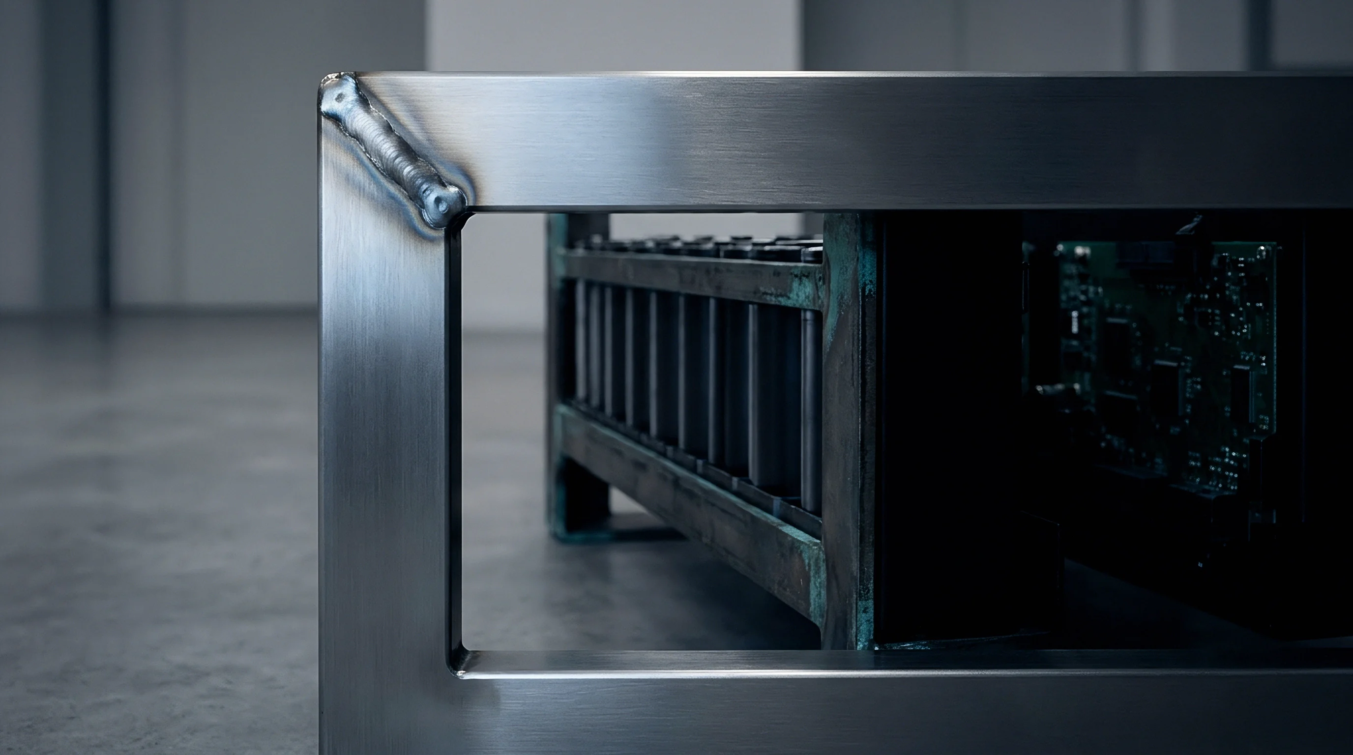
Engineers resolve this by zoning compression within the bays. Polyurethane microcellular sheets between alternating cell pairs or wavy leaf springs along compartment bulkheads absorb dilation locally. This prevents the aluminum perimeter from absorbing cyclic internal expansion loads that could fatigue longitudinal seam welds.
Several materials serve these retention and compliance roles:
- Micro-cellular polyurethane provides non-linear compression characteristics with low compression set under sustained thermal exposure, preventing force relaxation over ten-year service spans.
- Austenitic stainless steel tie-straps maintain high tensile yield strength and low creep rates, securing pack preload across extreme operational thermal envelopes.
- Silicone foam elastomers exhibit stable damping behavior across a broad temperature range from -40 degrees Celsius to 85 degrees Celsius, maintaining compliance during winter cold-soak events.
- Extruded aluminum endplates designed with variable thickness profiles minimize central wall bowing, distributing compressive stress evenly across the full active face of adjacent cells.
Under ISO 12405-4 vibration and shock dwell testing, an unverified compliant pad design allows cell relative motion to shear aluminum busbar weld joints.
Framing systems built without accounting for compression set lose clamp force as the elastomer takes a permanent set under hot operating conditions.
Cushion
Inter-cell cushions govern the local mechanics inside modern battery modules and cell-to-pack assemblies. These pads perform multiple functions within a crowded spatial boundary. They provide mechanical compliance to absorb reversible and irreversible cell swelling, deliver electrical isolation between adjacent metallic cell cans, damp high-frequency vibration inputs from the road surface, and establish a thermal barrier to delay or prevent cascade cell-to-cell thermal propagation.
Selecting a cushion material requires deep analysis of compressive stress-strain curves, long-term viscoelastic relaxation, and thermal degradation kinetics.
Conventional dense rubber materials fail in this role because their incompressibility causes high lateral expansion under load, known as a Poisson ratio close to 0.50. When compressed in a confined pack pocket, solid elastomers bulge outward against can vents and cooling plates, creating unmanaged shear forces. Micro-cellular foams and aerogel matrices bypass this failure mode by collapsing internal cellular voids under load.
This void collapse yields an effective Poisson ratio near zero, allowing the material to compress linearly through its thickness without generating destructive orthogonal strain.
Viscoelastic Relaxation and Long-Term Creep
Polymeric cushions subjected to continuous compressive strain experience stress relaxation over time. An initial beginning-of-life clamping pressure of 0.25 MPa applied to a polyurethane pad can decay to 0.12 MPa within 1,000 hours of operation at 45 degrees Celsius if the cushion material exhibits a high creep compliance coefficient. This relaxation lowers the effective preload below the threshold required to suppress graphite delamination, negating the original assembly design intent.
Designers must utilize materials with high molecular cross-link densities to suppress molecular chain slip and preserve preload throughout the warranty lifecycle.
Engineers evaluate long-term cushion performance by constructing master curves via time-temperature superposition testing. Compressing sample pads to 30 percent engineering strain under isothermal holds at 25, 45, and 65 degrees Celsius reveals their relaxation moduli. Polyurethane materials formulated with aromatic isocyanates frequently lose up to 40 percent of their instantaneous stress over five years of equivalent operational exposure.
High-performance crosslinked silicone matrices and ceramic-fiber composite papers demonstrate superior stability, retaining over 85 percent of their initial sealing and clamping force across equivalent service windows.
| Material Category | Density Range (kg/m³) | Initial Elastic Modulus (MPa) | Compression Set at 70°C (%) | Thermal Conductivity (W/m·K) | Flammability Classification |
|---|---|---|---|---|---|
| Polyurethane Foam | 240 – 400 | 0.35 – 1.20 | 12 – 25 | 0.06 – 0.09 | UL 94 HBF |
| Silicone Elastomer Foam | 250 – 500 | 0.20 – 0.85 | 2 – 5 | 0.08 – 0.14 | UL 94 V-0 |
| Silica Aerogel Composite | 180 – 300 | 1.50 – 4.50 | 1 – 3 | 0.018 – 0.024 | UL 94 V-0 |
| Ceramic Fiber Paper | 200 – 350 | 2.00 – 6.00 | < 1 | 0.05 – 0.10 | Non-combustible |

Acoustic Damping and Thermal Barrier Integration
Modern structural enclosures face strict noise, vibration, and harshness targets. Road surface inputs excite structural resonances within the floor pan, transmitting structure-borne acoustic energy into the passenger cabin. The cellular architecture of silicone and polyurethane inter-cell pads acts as a distributed mechanical damper.
The high loss factor of these elastomeric materials dissipates vibrational energy within the 200 Hz to 1,200 Hz frequency band, suppressing modal resonance amplification across the cell stack.
Thermal isolation demands are equally severe. When a cell enters thermal runaway, its skin can exceed 700 degrees Celsius in seconds. Direct aluminum-to-aluminum contact spreads that heat into adjoining cells, triggering cascading failures.
Inserting reinforced silica aerogel pads preserves mechanical compliance while delivering low thermal conductivity ~ under 0.025 W/m-K even under working compression. That thermal resistance holds back heat flux long enough for pack venting and cooling systems to arrest propagation.
Spec sheets frequently cite compression-deflection figures taken from unaged pads at room temperature, glossing over the stiffening that occurs after hundreds of thermal cycles.

Arithmetic
Calculating the preload equilibrium for a structural pack requires solving a multi-variable mechanical stack-up across temporal, thermal, and electrochemical dimensions. A proper preload analysis accounts for manufacturing tolerances, dynamic thermal expansion coefficients, non-linear pad stiffness curves, and cell swelling rates over the operational life of the pack. To demonstrate this optimization process, consider an engineered pack design consisting of a 24-cell series stack using 280 Ah prismatic lithium iron phosphate cells.
The worked calculation establishes the mechanical parameters required to keep cell face pressure between 0.15 MPa at beginning of life and 0.80 MPa at end of life. The nominal cell dimensions feature a width of 174 mm, a height of 207 mm, and a thickness of 72.0 mm, yielding an active contact area of 36,018 square millimeters. The assembly tolerance stack accounts for the cell can thickness tolerance of plus or minus 0.5 mm per cell, totaling plus or minus 12.0 mm across the unconstrained 24-cell array.
Each cell exhibits 1.2 percent reversible breathing strain and 8.0 percent irreversible end-of-life swelling strain.

Worked Stack Sizing Calculation
Stack length changes markedly between uncharged assembly and fully lithiated retirement. At baseline, twenty-four uncompressed cells measure 1,728.0 mm. Adding the worst-case positive tolerance of 12.0 mm brings the raw stack to 1,740.0 mm.
Left unchecked, irreversible swelling at 80 percent state of health adds another 5.76 mm per cell, or 138.24 mm of permanent elongation across the stack.
A rigid chassis cannot accommodate this magnitude of physical displacement without mechanical failure. Inserting 2.5 mm nominal thickness silicone foam cushions between every cell adds 25 inter-cell boundaries, providing an initial uncompressed cushion space of 62.5 mm. The structural enclosure dimensions are fixed by steel-reinforced tie-rods, establishing a rigid internal cavity length of 1,780.0 mm.
Compressing the assembly into this cavity during production applies an initial displacement to the cushions, generating the mandatory beginning-of-life preload force.

Stress-Strain Equilibrium Iterations
The silicone foam exhibits a non-linear compressive stress-strain profile characterized by the hyperelastic relationship where stress equals 0.85 times strain divided by the quantity one minus strain, raised to the second power. At assembly, the cushions are compressed to absorb the initial gap difference between the cavity and the manufactured cell stack. With a worst-case cell stack thickness of 1,740.0 mm and a cavity length of 1,780.0 mm, the total space remaining for the 25 cushions equals 40.0 mm.
Each cushion compresses from its initial 2.5 mm thickness to 1.6 mm, representing an initial engineering strain of 36.0 percent.
Entering this 36.0 percent strain value into the constitutive foam equation yields an initial beginning-of-life pressure of 0.267 MPa, comfortably above the 0.15 MPa delamination threshold. The total compressive force applied across the 36,018 square millimeter cell face equals 9,617 Newtons. The tie-straps counter this force with an equivalent tensile load.
Selecting two 304-stainless-steel tie-straps with a total cross-sectional area of 120 square millimeters results in an initial strap tensile stress of 80.1 MPa, well beneath the 205 MPa yield strength of the material.
End-of-Life Pressure Envelope Resolution
Over time, the expanding jelly rolls generate irreversible volumetric strain. With an elastic modulus of 193 GPa across a 1,780 mm run, the 304 tie-straps stretch elastically under load, granting back some mechanical compliance. At the same time, the swelling cells compress their own aluminum casings and active layers, showing a lumped bulk modulus of roughly 120 MPa along the stack axis.
Solving the coupled boundary equilibrium reveals that the cushions compress further to an engineering strain of 54.0 percent, while the tie-straps elastically elongate by 1.85 mm under a final tensile load of 25,200 Newtons. The resulting end-of-life pressure settles at 0.700 MPa, successfully avoiding the 0.80 MPa upper limit that triggers separator pore collapse. This iterative calculation confirms that the structural boundary maintains compliance across the entire service life while remaining within structural and electrochemical safety limits.
Beginning-of-Life Condition:
Stack Cavity: 1,780.0 mm
Cell Pack Thickness: 1,740.0 mm
Total Cushion Space: 40.0 mm (1.60 mm per pad)
Pad Preload Strain: 36.0%
Resulting Interface Pressure: 0.267 MPa
Total Clamp Force: 9.62 kN End-of-Life Condition (80% SOH, Full Charge):
Tie-Strap Elastic Elongation: 1.85 mm
Total Expanded Cavity: 1,781.85 mm
Cell Core Elastic Compression: 2.10 mm
Total Cushion Space: 28.75 mm (1.15 mm per pad)
Pad Final Strain: 54.0%
Resulting Interface Pressure: 0.700 MPa
Total Clamp Force: 25.20 kN
The design calculation demonstrates that structural strap elasticity must contribute at least ten percent of total pack compliance to avoid exceeding end-of-life pressure limits.
Sizing against nominal component drawings rather than statistical tolerance stacks guarantees trouble on the floor: high-limit cells inevitably over-stress assembly tooling or push clamp pressures past specification.
Tooling
Hitting repeatable preload targets on a production line requires dedicated tooling and closed-loop process feedback. Relying on torque-to-yield bolt specs is inadequate: thread friction between steel fasteners and cast aluminum housings varies by more than 30 percent across lots, scattering the actual clamp force delivered to the cell faces. Commercial pack lines rely on servo-electric or hydraulic presses that drive directly to force before the retention hardware is secured.
During automated assembly, cells and cushions feed into an adjustable nest. The press ram drives the endplate until multi-axis load cells read the prescribed clamping force across the contact face. While the servo ram holds that load, laser heads weld the tie-straps to the endplates, or robotic nut-runners run down fasteners against positive mechanical stops, taking fastener friction out of the preload equation entirely.

Inline Verification and Calibration Standards
Because cell can dimensions and cushion thicknesses vary, fixed-displacement pressing cannot work. Driving a ram to a set position crushes stacks running toward the upper tolerance limit while leaving thin stacks dangerously loose. Instead, production presses run multi-stage profiles: the tooling moves fast to a low touch threshold, establishes the specific stack’s zero datum, and then ramps under force control to the target pressure plateau.
Statistical process control software captures the final displacement distance at target force for every manufactured module. This displacement value serves as a quality gate. If the measured displacement falls outside established statistical control limits, the assembly fixture identifies a missing cushion pad, a doubled insulator sheet, or out-of-spec can geometry, automatically rejecting the module before high-value laser busbar welding occurs.
The following sequence details the precise mechanical operations executed during the cell pack compression process:
- Robotic array nesting aligns prismatic cells and inter-cell cushion sheets within the load frame, maintaining vertical and lateral registration tolerances within 0.25 mm.
- Servo press approach drives the primary compression platen forward at high speed until the load feedback indicates stack contact at a pre-clamp threshold of 500 Newtons.
- Force-controlled ramp applies a progressive linear compression rate not exceeding 2.0 mm per second, allowing air trapped within porous cushion structures to escape without tearing cell wrap insulation.
- Load dwell confirmation maintains target preload for an engineered dwell period of five to ten seconds, verifying that short-term viscoelastic relaxation remains within prescribed process bounds.
- Laser strap welding joins the high-strength retention straps to the structural endplates while the platen maintains holding pressure, minimizing thermal distortion of the structural joints.
- Platen retraction audit releases the external press load while internal load cells verify that final stack elastic spring-back does not exceed 0.15 mm.
Thermal Management Interface Integration
Vertical assembly forces dictate the thermal performance of bottom-chilled designs. Prismatic cells conduct heat through their base plates into extruded aluminum cold plates, a path bridged by gap fillers or structural adhesives to displace insulating air. Preload applied horizontally to the stack must not compromise the integrity of this thermal interface.
High longitudinal clamping loads tend to bow the cell array upward, lifting center cells off the cooling floor. That gap breaks the adhesive bond, degrading thermal conduction and causing local cell overheating during fast-charging cycles. Tooling fixtures resolve this issue by applying simultaneous dual-axis compression.
Vertical hold-down clamps press the cell bases flat against the cooling plane with a calibrated pressure of 0.05 MPa to 0.10 MPa while the primary horizontal press applies the longitudinal stack preload, ensuring optimal thermal and mechanical alignment.
A production line that omits the platen dwell step seals packs with unmeasured viscoelastic force relaxation, compromising initial stack pressure calibration.
Trimming the five-second dwell to chase line takt time lets instantaneous material relaxation drop beginning-of-life preload below engineering specifications.

Qualification
Validating a mechanical preload system demands testing under combined environmental, mechanical, and electrical stresses. Prototype pack assemblies must survive rigorous test sequences designed to accelerate the failure modes encountered during ten to fifteen years of vehicle operation. Qualification protocols evaluate structural integrity, force retention, and electrochemical performance under extreme operational regimes.
Standard automotive testing combines cyclic thermal aging, multi-axis random vibration, mechanical shock, and continuous electrical cycling within hermetically sealed environmental chambers.
These trials expose weak links in the retention design before tooling prints are released to suppliers. Programs verify aluminum weld fatigue life, retention strap stretch, and compression pad creep under combined loads. Thin-film pressure mapping sheets and piezoelectric load washers embedded within test modules stream stack pressures continuously, catching dynamic force peaks during thermal shocks and high-current discharge bursts.
Environmental and Dynamic Load Sequences
Module and pack assemblies undergo severe vibration profiles defined by international standards such as UN 38.3, ISO 12405-4, and SAE J2380. Testing mounts the test assembly to a multi-axis electrodynamic shaker table inside a climate chamber. The test profile applies random vibration energy distributions from 10 Hz to 500 Hz, with root-mean-square acceleration levels exceeding 2.8g across longitudinal, transverse, and vertical axes.
Modules must simultaneously endure ambient temperature swings between -40 degrees Celsius and 75 degrees Celsius.
Vibration dwell testing reveals whether the mechanical preload system prevents cell relative motion. If the clamping force decays during thermal cold-soaks, the reduced frictional grip allows individual cells to shift along the mounting plane. This micro-motion transfers dynamic cyclic shear loads directly into the laser-welded busbars connecting the cell terminals.
Busbars subjected to these unintended stresses experience fatigue failure at the weld roots, causing catastrophic electrical open-circuits or high-resistance electrical arcs under heavy vehicle acceleration.
Standardized Protocols for Clamping Systems
Certification requires documented proof that the retention structure will not provoke short circuits under extreme impacts. Crush and penetration trials under UL 2580 and ECE R100.03 require modules to absorb structural deformation without internal cell breach or thermal runaway. Maintaining a balanced, predictable preload distribution avoids stress concentrations that could pinch or shear internal separator films during side collisions.
Post-test teardowns provide the final check on design validity. Technicians disassemble aged modules to examine internal components, inspecting polyolefin separators for localized thinning, checking current-collector foil roots under scanning electron microscopy, and surveying the cell cans for fretting wear. Uniform electrode coloration and an absence of lithium plating confirm that stack pressure stayed inside the electrochemical stability window through qualification.
Pack endurance clauses routinely require cell face contact pressure to stay between 0.10 MPa and 0.90 MPa throughout all ISO 12405-4 vibration stages, under penalty of the pack builder absorbing all redesign and tooling rework costs.