Ultrasonic Nondestructive Testing of Encapsulated Structural Lithium Ion Cell Bonding
Ultrasonic phase inversion and time-of-flight gating accurately quantify bond disbonds, voids, and adhesion integrity in encapsulated structural battery packs.

Acoustics
Pressure wave propagation through structural battery enclosures depends directly on the mechanical properties of the potting compounds and metal casings. In cell-to-pack architectures, traditional mechanical modules are eliminated. Prismatic, pouch, or cylindrical cells bond straight to structural side plates, cooling ribbons, and bottom trays using polyurethane, epoxy, or thermally conductive silicone gap fillers.
These adhesive layers transfer chassis torsional loads and road shock directly through the cell envelopes, meaning non-destructive inspection of the embedded joints relies on stress waves passing through materials with widely divergent physical characteristics.
Heat builds quickly while sound waves reflect at internal interfaces and air voids block wave propagation altogether. Densities across a structural battery module range from 0.0012 grams per cubic centimeter in trapped air pockets to 7.85 grams per cubic centimeter in nickel-plated steel cell casings. Sound velocities span an equally wide range, moving at 343 meters per second through ambient air, 1500 to 2600 meters per second through structural polymers, and over 6300 meters per second through aluminum heat-sink plates.
High attenuation in viscoelastic encapsulation polymers rapidly absorbs high-frequency acoustic energy, limiting beam penetration depth.

Impedance Discontinuities across Encapsulated Cell Interfaces
Boundary reflections govern how much acoustic energy crosses from an adhesive layer into a lithium ion cell wall. Characteristic acoustic impedance is the product of material density and longitudinal sound velocity. When an acoustic beam hits an interface between two materials with identical impedance, energy passes through without reflection; large impedance mismatches send most of the energy bouncing back toward the sensor.
A structural polyurethane layer with a density of 1.25 grams per cubic centimeter and a longitudinal sound velocity of 1950 meters per second has a characteristic acoustic impedance of 2.44 Megarayls. An adjacent aluminum 3003-H14 cell wall measures 17.0 Megarayls. The reflection coefficient at an intact polyurethane-to-aluminum joint equals 0.56, meaning 56 percent of the incident sound pressure reflects, while 44 percent transmits into the cell casing.
An air void along that same bond line presents an impedance of just 0.0004 Megarayls. This interface yields a reflection coefficient of 0.9999, resulting in near-total reflection of the wave energy.
| Material Layer | Density (g/cm³) | Longitudinal Velocity (m/s) | Acoustic Impedance (MRayl) | Attenuation at 5 MHz (dB/cm) |
|---|---|---|---|---|
| Air Void (Standard Temp/Pressure) | 0.0012 | 343 | 0.0004 | 120.0 |
| Structural Polyurethane Foam | 0.45 | 1250 | 0.56 | 18.5 |
| Thermally Conductive Epoxy Adhesive | 1.55 | 2400 | 3.72 | 6.2 |
| Structural Silicone Gap Filler | 2.10 | 1050 | 2.21 | 22.4 |
| Aluminum Alloy 3003-H14 | 2.73 | 6320 | 17.25 | 0.4 |
| Nickel-Plated Steel (Cylindrical Can) | 7.85 | 5900 | 46.32 | 1.2 |
| Pouch Cell Laminated Foil Shell | 1.15 | 2100 | 2.42 | 8.7 |
These reflective boundaries dictate the amplitude returning to the transducer. Inspection requires energy to cross a series of distinct interfaces: transducer shoe, coupling layer, outer enclosure sheet, structural adhesive layer, cell wall, and internal electrolyte interface. Each transition reflects a fraction of the wave, weakening the echo returned from deeper boundaries.
Adding aluminum oxide or boron nitride particles to high-density gap fillers brings their acoustic impedance closer to aluminum levels, improving energy transmission into the cell wall, though it accelerates scattering losses within the adhesive layer itself.

Frequency Trade-Offs in Multi-Layer Acoustic Attenuation
Choosing a transducer center frequency means balancing spatial defect resolution against signal penetration depth. High acoustic frequencies have short wavelengths capable of resolving sub-millimeter delaminations and fine porosity, but they attenuate heavily inside filled polymers and structural foams from viscoelastic absorption and scattering. Scattering losses scale exponentially with center frequency whenever particle diameters approach the acoustic wavelength.
A structural epoxy with a density of 1.35 grams per cubic centimeter and sound velocity of 2450 meters per second yields a characteristic acoustic impedance of 3.31 MRayl.
Operating a transducer at 10 Megahertz through a 10-millimeter layer of thermally conductive polyurethane attenuates the acoustic signal by more than 40 decibels over the round-trip path, dropping the signal-to-noise ratio below usable evaluation thresholds. Dropping the central frequency to 2.25 Megahertz expands the longitudinal wavelength from 0.24 millimeters to 1.06 millimeters within the adhesive. This lower frequency reduces round-trip absorption losses to roughly 12 decibels over the same 10-millimeter path, leaving sufficient dynamic range to detect disbond reflections at the far adhesive interface.
Spatial resolution degrades as center frequency drops. The minimum resolvable planar flaw size scales with transducer wavelength, bounded by the Rayleigh scattering limit. A 2.25 Megahertz probe in a gap filler with a sound velocity of 2200 meters per second produces a wavelength of 0.98 millimeters.
Defects smaller than 0.5 millimeters in diameter fail to return distinct specular reflections, showing up instead as background scatter. Resolving micro-porosity in thin structural adhesive lines requires balancing center frequencies within a tight window between 3.5 Megahertz and 5.0 Megahertz.
Phase velocity dispersion across viscoelastic adhesives introduces pulse distortion as broadband ultrasonic energy moves through structural packs. High-frequency spectral components travel slightly faster than low-frequency components in highly damped polymers, broadening returning wave pulses over time and overlapping reflection signals from closely spaced interfaces. High-resolution digitizers must sample returning waveforms at high frequencies to preserve phase signatures across thin cell envelope boundaries.
How do changes in structural adhesive glass transition temperature during pack environmental thermal cycling alter acoustic velocity profiles enough to skew automated bond depth calculations on high-speed inspection lines?


Probe
Ultrasonic transducers convert electrical excitation pulses into mechanical vibrations that travel directly through structural encapsulation media. Sensor architecture determines how wave energy focuses inside embedded cell bond lines. Selecting transducer element materials, aperture geometries, and delay lines fixes the spatial envelope of the inspection before software processing begins.
Echoes decay quickly in damped media, and air gaps block reflection signals. Piezocomposite active elements, which combine vertical lead zirconate titanate rods embedded in a polymer matrix, outperform solid ceramic discs for battery pack inspection. Piezocomposites deliver lower acoustic impedance, matching structural adhesives more closely, while providing broadband responses exceeding 80 percent fractional bandwidth.
That broadband performance keeps pulse durations short in time, allowing clear resolution of closely spaced interface echoes.

Transducer Selection for Multi-Layer Structural Assemblies
Element design dictates beam steering, focal depth, and signal bandwidth across encapsulated pack layers. Single-element immersion transducers provide clean acoustic profiles but require mechanical scanning across the entire pack surface, creating throughput bottlenecks. Linear phased array transducers feature 64 to 128 individual elements driven by independent delay channels.
The electronics sweep and focus ultrasonic beams without mechanical probe movement, accelerating spatial mapping along long structural bond lines.
Focal spot geometry determines the smallest detectable bond flaw. Unfocused transducers produce a beam that spreads naturally in the far field, governed by element diameter and sound wavelength. Curved focusing lenses or phased array electronic focusing concentrate acoustic energy into a narrow waist at the bond depth.
A 5.0 Megahertz phased array probe focused at a depth of 15 millimeters inside an adhesive layer achieves a lateral beam width of 0.8 millimeters at the focal plane, allowing precise sizing of localized structural disbonds.
Array pitch, element width, and inter-element spacing control grating lobe generation during electronic beam steering. Steering ultrasonic beams at high angles across cell module walls with wide element pitches introduces spurious acoustic lobes that bounce off internal cell components, generating false defect signals. Maintaining element pitch below half the acoustic wavelength in the coupling medium suppresses secondary grating lobes, preserving high signal contrast across complex pack internal boundaries.

Coupling Media and Contact Dynamics on Potting Resins
Energy transmission into a structural battery pack relies on an uninterrupted physical bridge between the sensor face and the potting material. Fluid couplants, such as deionized water or specialized gels, displace microscopic air gaps at surface contact points. Water-submerged immersion testing offers optimal acoustic coupling consistency but introduces fluid contamination risks to exposed electrical busbars and high-voltage connections in structural battery designs.
Dry-coupled elastomeric delay lines eliminate liquid contamination risks during inline manufacturing inspection. Synthetic rubber or hydrophilic polymer shoes conform under moderate mechanical pressure to textured potting resin surfaces. These soft shoes transmit compressional waves with minimal insertion loss while absorbing surface roughness variations up to 0.5 millimeters peak-to-valley.
Mechanical pressure on the probe housing must stay within controlled boundaries to prevent distortion of compliant pack covers during scanning.
- Measure the total thickness and sound velocity of the encapsulation layer using a calibrated reference block.
- Determine the minimum resolvable defect size based on structural shear load transfer limits.
- Calculate the required acoustic wavelength using half the target defect diameter as the spatial threshold.
- Select the highest operational center frequency that maintains an acceptable signal-to-noise ratio above twelve decibels through the attenuation path.
- Match the transducer element aperture size to the targeted focal depth using a calculated Rayleigh distance equation.
Air-coupled ultrasonic testing completely removes physical contact requirements, operating transducers across air gaps ranging from 10 to 50 millimeters. Huge acoustic impedance mismatches between air and solid media generate massive reflection losses, exceeding 100 decibels for two-way insertion paths. Air-coupled systems require high-power excitation transmitters delivering burst voltages up to 1000 volts alongside low-noise preamplifiers to extract weak returning signals above noise floors.
Contact stability governs signal amplitude consistency on textured polyurethane surfaces.


Echo
Reflected signal waveforms contain time and amplitude data revealing physical conditions deep inside potted battery modules. High-speed analog-to-digital converters digitize raw radio-frequency A-scan traces at sampling rates up to 500 Megasamples per second. Software algorithms extract wave amplitude peaks, phase inversions, and time-of-flight arrivals to convert linear waveforms into detailed two-dimensional spatial maps.
Evaluating raw radio-frequency waveforms allows technicians to distinguish between mechanical disbonds, resin starvation, and fully intact structural bonds. High frequencies scatter in filled matrices, but phase shifts pinpoint unbonded boundaries even when spatial resolution degrades. Signal conditioning includes digital bandpass filtering to strip out mechanical machine vibration and high-frequency electrical noise generated by nearby automation equipment.
Phase Inversion Signatures at Disbond Boundaries
Polished metal interfaces and air gaps generate opposite polarities in reflected sound waves. Phase polarity analysis provides absolute differentiation between an intact structural bond and an unbonded air boundary. When sound waves travel through a lower impedance potting compound and strike a higher impedance metal cell casing, the reflected pressure wave maintains its original phase polarity, displaying an initial positive amplitude pulse on the A-scan trace.
An air void or delamination at the adhesive-to-metal boundary presents an acoustic impedance dramatically lower than the potting compound. Reflection off this acoustic boundary flips the reflected wave phase by 180 degrees, causing the A-scan trace to display an initial negative amplitude pulse. Automated signal processing algorithms monitor the sign of the first major reflection peak within designated depth windows, classifying bond integrity without relying solely on signal amplitude thresholds.
| Bond Interface State | Reflected Amplitude (vs Ref Block) | Phase Polarity Shift | Time-of-Flight Shift | Spectral Attenuation Trend |
|---|---|---|---|---|
| Intact Structural Bond | Moderate (-6 dB to -12 dB) | Non-inverted (Positive) | Nominal calculated depth | High frequency loss via transmission |
| Gross Air Disbond / Delamination | Very High (0 dB to -2 dB) | Inverted (Negative) | Slight shift (surface echo) | Low attenuation (total reflection) |
| Zero-Gap Kissing Bond | Moderate to High (-4 dB to -8 dB) | Variable / Mixed | Nominal calculated depth | Modest loss; shear waves blocked |
| Resin Starvation / Micro-porosity | Low to Moderate (-10 dB to -18 dB) | Multiple micro-peaks | Broadened pulse return | Heavy high-frequency scattering |
| Uncured Soft Adhesive Matrix | Moderate (-8 dB to -14 dB) | Non-inverted (Positive) | Delayed ToF (lower c) | Extreme low-frequency absorption |
Adhesive curing states alter sound speed within structural resins. An uncured two-part polyurethane displays a lower longitudinal wave velocity compared to a fully cross-linked polymer matrix. As curing progresses, sound speed increases by 15 to 30 percent, shifting time-of-flight reflections earlier in the recording window.
Tracking time-of-flight shifts across cured modules validates adhesive curing profiles non-destructively on assembly lines.

Time-of-Flight Gating and C-Scan Mapping Resolution
Digital capture hardware isolates specific depth layers by opening narrow temporal reception windows relative to the initial excitation pulse. Time-of-flight gating extracts acoustic peak values corresponding strictly to the spatial plane occupied by the cell-to-adhesive interface. Signal evaluations ignore front-wall reflections from outer pack covers and back-wall reflections from internal cell components, concentrating data analysis exclusively on structural bond layers.
Contractual compliance under ASTM E2580 demands complete phase reversal analysis across every gated reflection window before certifying adhesive joint integrity.
C-scan imaging combines spatial positional coordinates from X-Y encoder axes with amplitude or phase data extracted from gated time windows. Every spatial grid point maps to a colored pixel, generating a planar view of structural bond continuity across battery surfaces. High-density C-scans reveal adhesive flow patterns, air bubble entrapment channels, and unbonded corner regions across prismatic cell matrices.
Spatial interpolation routines smooth image pixel arrays, but raw uninterpolated acoustic data carries the precise physical dimensioning needed for structural engineering evaluations. Assessing multi-layer adhesive stacks requires tracking pulse phase inversion across bond line samples. Disbond area calculations require applying precise intensity threshold masks, typically setting critical rejection boundaries at six decibels below intact bond reference standards.

Does Synthetic Aperture Focusing Enhance Kiss Bond Detection?
Multi-angle beam combination algorithmically sharpens planar defect edges in structural adhesive layers. Synthetic Aperture Focusing Technique synthesizes a large virtual aperture by mathematically summing acoustic signals collected across multiple scan positions of a small transducer. The processing algorithm applies dynamic time-delay corrections to overlapping A-scans, phase-aligning signals reflected from specific focal points within the structural adhesive volume.
Focusing improvements from synthetic aperture processing narrow the acoustic beam width throughout the inspection depth, increasing lateral spatial resolution down to half a wavelength. Enhanced lateral resolution resolves fine crack networks, micro-porosity channels, and adhesive edge tailing along structural battery ribs. Synthetic algorithms require significant processing capacity, running high-speed matrix multiplications for every digitized voxel inside structural bond volumes.
Zero-gap kissing bonds present severe challenges even to focused acoustic beams. Kissing bonds occur when adhesive surfaces sit in intimate physical contact with cell casings under mechanical compression, but lack chemical cross-linking or physical shear adhesion strength. Standard longitudinal ultrasonic waves pass directly across these compressed interfaces with minimal amplitude drop or phase shift.
Detection requires specialized oblique-incidence shear wave techniques or nonlinear harmonic ultrasonic analysis, where wave energy generates second-harmonic frequencies proportional to non-linear interface stiffness variations.
Field evaluation trials proved that processing real-time synthetic aperture algorithms across three-meter structural pack floors increased inspection station computer hardware costs by $35,000 per assembly line.

Void
Defects inside structural battery adhesive layers span a wide range of physical structures and mechanical failure modes. Manufacturing anomalies arise during adhesive dispensing, module staging, or potting cure cycles. Understanding defect morphology allows quality engineers to correlate ultrasonic signal anomalies directly with mechanical structural joint failure modes.
Glue cures unevenly, and trapped bubbles scatter energy. Structural adhesives must maintain unbroken contact across both cell casing aluminum walls and outer pack frames. Disbonds thermally isolate localized cell zones while transferring bending stresses unevenly during vehicle operation.

Categorization of Structural Adhesive Bond Defects
Internal flaws inside cell-to-pack adhesive bonds disrupt both stress distribution and thermal management. Delamination voids create complete physical separation between the cell wall and structural adhesive. Air entrapment bubbles form spherical voids during high-speed adhesive dispensing or low-pressure potting operations.
Cohesive failure manifests as mechanical cracking within the structural adhesive matrix itself, leaving cured resin bonded to both metal surfaces.
- Interfacial Adhesive Disbond eliminates mechanical load transfer between the aluminum cell wall and the encapsulation matrix, leading to structural stress concentration.
- Cohesive Foam Voiding reduces the effective shear modulus of polyurethane structural formulations, causing local thermal insulation and hot-spot accumulation.
- Zero-Gap Kissing Contact permits longitudinal acoustic transmission while offering zero mechanical shear strength under pack torsional loading.
- Thermally Conductive Filler Aggregation alters local acoustic velocity, creating false positive disbond readings during automated gating routines.
Thermal implications of bonding voids rival mechanical structural impacts. Pouch and prismatic cells rely on unbroken contact paths through thermally conductive adhesives to export heat toward liquid cooling plates during high C-rate charging. An air void presents thermal conductivity near 0.026 Watts per meter-Kelvin, compared to 1.5 to 3.0 Watts per meter-Kelvin for filled structural epoxies.
Trapped air voids force local cell temperatures upward during fast charging, triggering localized thermal degradation and accelerated capacity loss in affected lithium ion layers.
When structural adhesive covers less than eighty-five percent of the cell casing surface, mechanical strain concentrates at the unbonded edges during chassis flexure.
Mechanical stress concentrations multiply around structural disbond edges. In structural battery packs, cells act as load-bearing chassis components. Flexural and torsional chassis forces route mechanical shear stress directly through cell-to-pack bond interfaces.
Unbonded regions create localized stress peaks at adjacent intact bond edges, accelerating fatigue tearing of thin aluminum pouch walls or prismatic casings under long-term road vibration.

Kissing Bonds and Acoustic Shear Transmission Limits
Compressional ultrasound passes easily across unbonded surfaces held together under tight mechanical clamp pressure. Longitudinal waves compress materials perpendicular to wave fronts, pushing contact surfaces together during positive pressure cycles. When mechanical compression forces unbonded surfaces into intimate mechanical contact, longitudinal acoustic reflection drops to levels matching fully cured intact chemical bonds.
Shear waves vibrate particles parallel to wave fronts, applying pure transverse shearing forces across structural interfaces. Liquids, gases, and unbonded dry interfaces cannot transmit shear stresses, yielding zero shear wave transmission (μ = 0). Inspecting structural cell bonds with transverse shear waves exposes zero-gap kissing bonds immediately.
The shear wave reflects completely off the non-bonded interface despite physical contact, yielding a clear disbond amplitude signal.
Teardown evaluations of returned structural packs reveal zero-gap disbonds that maintain complete compressional contact. Generating shear waves inside encapsulated packs requires specialized angle-beam wedge transducers or mode-conversion techniques. Angle wedges launch longitudinal waves into delay shoes at calculated critical angles, converting wave modes into transverse shear waves inside outer metal pack frames.
High acoustic shear attenuation within potting polymers limits shear wave propagation distances, forcing inspection heads close to target bond lines.
While minor interfacial disbond areas under ten percent are sometimes assumed to carry no structural risk, mechanical shaker table testing showed crack propagation across those same disbond boundaries after just 1200 fatigue cycles.


Line
High-volume pack assembly lines integrate non-destructive inspection stations directly into the manufacturing flow. Inline testing verifies structural adhesive coverage before packs move to electrical busbar welding and structural top cover closure. Inline inspection hardware faces intense takt time pressure, demands high spatial repeatability, and operates under harsh industrial environmental conditions.
Automated inspection gantries move high-density sensor arrays across multi-meter pack spaces in under 60 seconds. Fast movements require mechanical positioning repeatability within ± 0.05 millimeters to maintain acoustic beam alignment across tight cell gaps.
Automation Gantries and Robotic Path Accuracy
Six-axis mechanical arms and Cartesian gantries move inspection heads across complex structural pack geometries. Robotic arms provide spatial flexibility, wrapping around curved pack frames and angled cell modules. Cartesian gantries deliver higher mechanical stiffness and vibration isolation, achieving superior positioning accuracy across flat, multi-cell battery floors.
Surface height variations across large structural battery trays disrupt focal depth settings. Active height tracking systems use optical laser displacement sensors mounted alongside ultrasonic probes. Lasers map surface contours millisecond by millisecond, sending instantaneous displacement feedback to high-speed Z-axis linear motor stages.
Maintaining constant transducer standoff distances preserves uniform ultrasonic beam spot sizes across uneven structural potting layers.
- Acoustic Coupling Stability governs signal-to-noise ratios during rapid gantry movement across complex pack geometries.
- Positional Encoder Synchronization matches acoustic waveform arrivals to precise physical coordinates along the tool path.
- Real-Time Threshold Hardware executes signal envelope filtering within dedicated field-programmable gate arrays to prevent line bottlenecks.
- Automated Calibration Blocks perform periodic sensitivity verification against reference flat-bottom holes during production pauses.
Positional encoders stream quadrature pulses directly into ultrasound data acquisition cards. Hardware triggers fire acoustic transmitter pulses at spatial distance increments rather than temporal time intervals. Spatial pulse triggering prevents grid image distortion when gantries accelerate or decelerate around module corners, ensuring uniform pixel density across entire pack surface maps.

Takt Time Synchronization and Spatial Resolution Controls
Production line speeds constrain the number of acoustic firings possible across a given square meter of pack area. A structural battery tray measuring 2.0 meters by 1.2 meters contains 2.4 square meters of surface area. Inspecting this area on a 0.5-millimeter raster spatial grid requires 9.6 million distinct acoustic measurement points.
Achieving a 45-second station cycle time demands processing acoustic pulse repetition frequencies exceeding 213 Kilohertz.
Single transducer elements cannot achieve these pulse firing rates due to acoustic reverberation limitations. Sound pulses must decay completely inside the target material before the next pulse fires, avoiding ghost echo interference. Multi-channel phased array systems divide total surface area across 128 to 512 parallel electronic channels.
Parallel acquisition lowers per-channel pulse firing rates to manageable levels below 2 Kilohertz, preserving high spatial mapping resolution while maintaining high-speed line takt times.
In-line acoustic testing adds three to five percent to pack assembly capital expense while cutting field warranty reserves by order of magnitude.
Data throughput from multi-channel digital acquisition systems generates massive raw data streams. A 256-channel system digitizing 512 samples per channel at 100 Megasamples per second and 12-bit resolution produces raw data flows exceeding 38 Gigabytes per minute. Onboard Field-Programmable Gate Arrays (FPGAs) execute real-time peak detection, phase analysis, and time-of-flight gating directly inside acquisition hardware, compressing raw RF traces into light scalar image pixels before streaming data across plant industrial Ethernet backbones.
Specification clause ISO 18563-1 mandates annual electronic channel delay calibration for all inline multi-channel phased array controllers, altering how maintenance schedules are tracked on automated structural pack lines.


Yield
Commercial viability in structural battery cell integration rests on balancing non-destructive testing capital expenditure against scrap costs and field failure liability. Structural battery packs cannot be easily disassembled; once potting adhesives cure around embedded cells, disbonding or cell replacement becomes economically unviable. Identifying defective structural bonds before packs progress downstream prevents scrapping expensive functional battery cells, battery management electronics, and high-current busbar assemblies.
Tooling costs add up and scrap rates spike early in production runs. Non-destructive inspection hardware represents a major upfront Non-Recurring Engineering (NRE) investment during battery line setup. Commercial decision-makers evaluate equipment amortization against avoided downstream scrap, warranty reserves, and brand exposure from structural field failures.
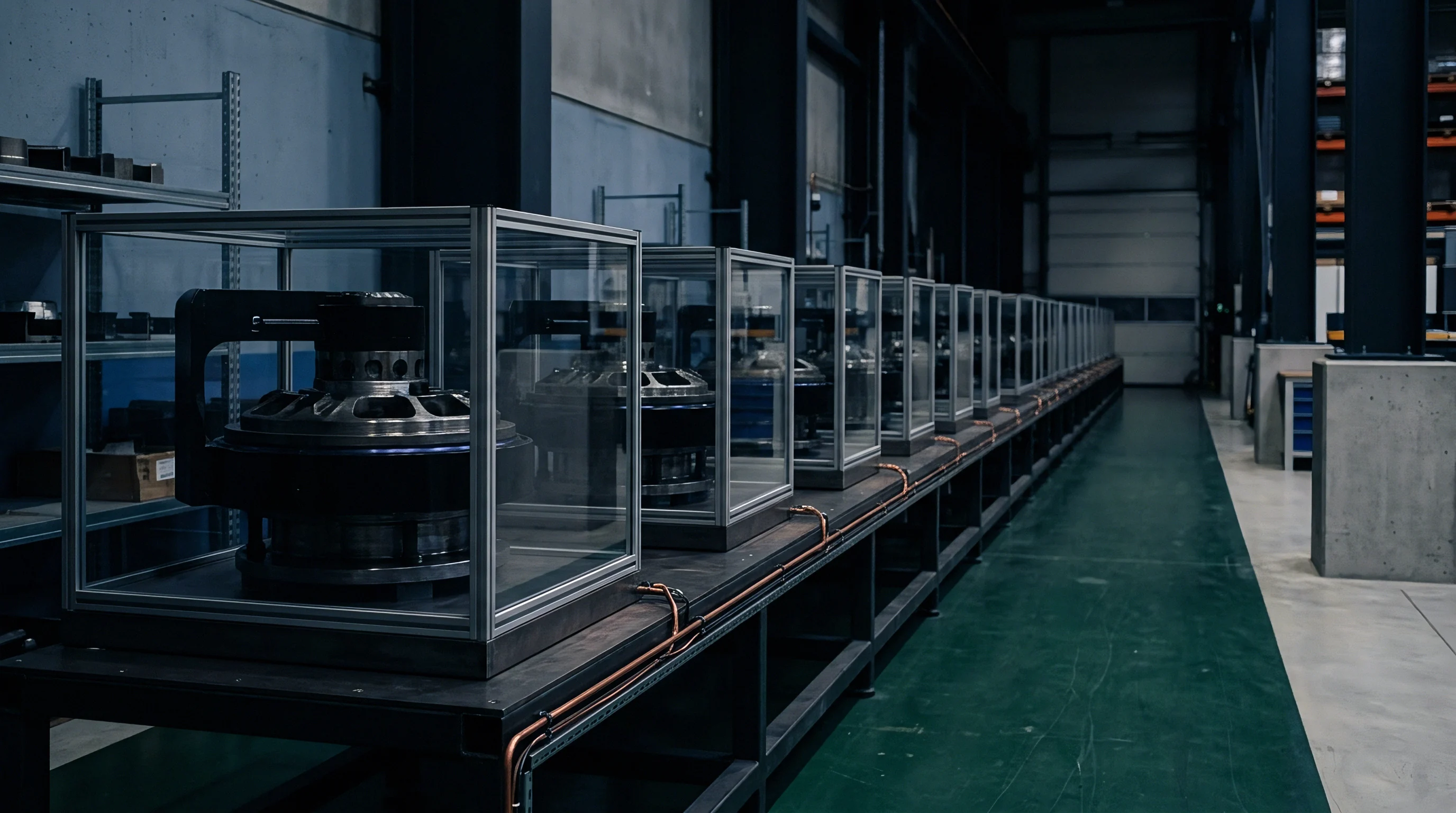
Capital Allocation for Inline Phased Array Tooling
Upfront expenditure on automated inspection gantries varies sharply between single-element squirt systems and multi-channel matrix arrays. High-density phased array gantries requiring multi-axis linear motors and custom dry-coupling wheels cost significantly more upfront than basic gantry options. Amortizing hardware costs across a 100,000-unit annual pack production run equates to modest tooling costs per produced pack.
| Inspection System Architecture | Upfront Capital Expenditure (USD) | Station Takt Time (per m²) | Consumables & Tooling Wear / Year | False Reject Rate Index |
|---|---|---|---|---|
| Single-Element Immersion C-Scan Tank | $180,000 – $250,000 | 12 – 18 minutes | $8,000 (Fluid filtration/rust inhibition) | 0.02 (Baseline reference) |
| Dry-Coupled Linear Phased Array Gantry | $450,000 – $650,000 | 1.5 – 2.5 minutes | $24,000 (Elastomeric wheel replacement) | 0.05 (Surface texture sensitivity) |
| High-Density Matrix Phased Array Gantry | $850,000 – $1,200,000 | 0.5 – 0.8 minutes | $38,000 (Multi-element shoe sets) | 0.03 (Advanced phase filtering) |
| Air-Coupled Non-Contact Ultrasonic Array | $320,000 – $480,000 | 3.0 – 5.0 minutes | $5,000 (No physical shoe contact) | 0.12 (High ambient acoustic noise) |
Operational costs extend beyond initial equipment purchases. Elastomeric dry-coupling shoes wear out under friction against rough potting resin surfaces, demanding replacement every 15,000 scan cycles. Calibration reference blocks containing artificial flat-bottom holes drilled to ASTM E1001 specifications require formal metrology recertification annually.
Plant maintenance teams must factor specialized ultrasound technician training into long-term operational budget allocations.

Contractual Defect Thresholds and Scrap Allocation
Quality agreements specify exact allowable void sizes, total disbond percentages, and scrap liabilities before production tooling commences. Cell suppliers, adhesive chemical manufacturers, and vehicle OEMs frequently dispute financial responsibility for structural bond rejections. Establishing clear physical defect criteria inside master supply agreements prevents expensive legal disputes when structural packs fail quality gates.
A typical structural battery specification sets a maximum single disbond area limit of 100 square millimeters along cell side walls, with total unbonded surface area capped at 5.0 percent of total contact faces. Any single void bridging the cooling plate boundary larger than 25 square millimeters triggers immediate module rejection due to local thermal runaway acceleration risks. Quality clauses cite ASTM E2580 as the governing standard for ultrasonic image interpretation and acceptance limits.
Negotiating quality guarantees with pack assemblers requires inserting strict spatial void limits into the master service agreement. Commercial contracts assign financial liability based on root-cause failure location. If an ultrasonic C-scan shows widespread micro-porosity caused by improper chemical mixing of two-part polyurethane resins, the adhesive chemical vendor absorbs the scrapped pack material cost.
If disbonds originate from oil contamination on cell walls, the cell casing washing equipment supplier or cell manufacturer absorbs the financial penalty.
Integrating high-speed ultrasonic NDT directly into structural cell bonding lines converts subjective bond evaluation into quantitative physical measurement. Automated phase inversion analysis, spatial time-of-flight gating, and matrix phased array gantry tracking yield accurate planar maps of encapsulated joints. Structural battery manufacturers leverage these non-destructive acoustic insights to hold high safety margins, enforce strict supply chain quality boundaries, and lock in predictable vehicle pack production yields.