Triaxial Fiber Bragg Grating Telemetry Integration in Pouch Cell Enclosure Architecture
Triaxial fiber Bragg grating arrays resolve multi-axis strain and thermal drift inside pouch enclosures while maintaining hermetic seal boundaries.


Optics

Interferometric Core Physics and Core Grating Pitch
Fiber Bragg grating sensors rely on periodic refractive index modulations inscribed in the germanium-doped silica core of a single-mode optical fiber. Light traveling through the core reflects a narrow wavelength band centered at the Bragg condition and transmits all other spectral components. This nominal center wavelength shifts in proportion to mechanical strain and temperature changes along the active grating length.
Inside battery enclosures, the 125-micrometer glass-clad silica fibers provide a lightweight telemetry channel unaffected by electromagnetic interference during high-rate pouch cell charging cycles.
Thermal sensitivity produces roughly a 10 picometers per kelvin shift near the 1550 nanometer telecom window, while mechanical longitudinal strain induces approximately 1.2 picometers per microstrain. Spatial multiplexing permits up to sixteen discrete sensing points along a single optical bus using wavelength division division interrogators. Resolving wavelength shifts down to 0.1 picometers at acquisition frequencies above two kilohertz, the interrogator captures localized acoustic emissions and transient thermal events before internal pouch degradation turns into runaway thermal decomposition.
A polyimide-coated single-mode fiber registers mechanical strain within 0.5 microstrain accuracy across operating temperatures from minus 40 to plus 85 degrees Celsius.
Embedding optical sensors in a multi-layer pouch stack creates localized pressure gradients whenever the fiber diameter exceeds standard separator thickness. Standard lithium-ion separators run between 9 and 20 micrometers thick, so placing a bare 125-micrometer fiber directly between anode and cathode forms a physical clearance step. During fast charging, that step drives localized current crowding and lithium plating along the fiber axis.
To avoid this, the optical line is routed through the inactive perimeter border or embedded inside structural compression pads outside the pouch foil boundary.
Thermal excitation and mechanical deformation create cross-talk that requires explicit mathematical decoupling. A single-axis Bragg grating cannot separate axial tensile elongation from ambient heating without external reference sensors. Using triaxial rosette grating configurations or dual-core birefringent fibers provides the independent equations needed to isolate mechanical strain tensor components from absolute thermal drift.
Automated winding tooling applying continuous acrylate jackets mitigates handling risks associated with fragile optical fibers.


Gland

Hermetic Penetration and Boundary Sealing
The boundary between the internal pouch volume and the exterior pack wiring harness is the main hermetic vulnerability in optical telemetry setups. Normal cycling and venting release volatile organic solvents like dimethyl carbonate and ethyl methyl carbonate. Prolonged exposure to carbonate vapor at 60 degrees Celsius causes standard elastomer grommets to soften and swell, compromising enclosure ingress protection.
Glass-to-metal seals or specialized fluoropolymer feedthrough glands maintain the seal under continuous differential pressure.
Feedthrough fixtures use precision torque-limiting gland nuts to compress a fluoroelastomer olive against the bare silica cladding. Torque exceeding 0.8 newton-meters shears the fiber core, whereas under-torquing allows electrolyte vapor to travel along the fiber surface and contaminate external optical connectors. Hermeticity specs require helium leak rates below 1.0 multiplied by 10 to the minus 8 standard cubic centimeters per second under a 100 kilopascals differential across the enclosure wall.
| Feedthrough Architecture | Operating Temperature Band | Helium Leak Rate Boundary | Maximum Axial Fiber Load | Enclosure Ingress Rating |
|---|---|---|---|---|
| Compression Olive FFKM | -40 to +125 deg C | 5.2e-8 mbar l/s | 12 N | IP68 / IP69K |
| Fused Silica Capillary Solder | -50 to +180 deg C | 1.1e-9 mbar l/s | 45 N | IP69K Hermetic |
| Epoxy Potting Flange | -20 to +85 deg C | 3.4e-6 mbar l/s | 8 N | IP67 |
| PTFE Swaged Ferrule | -40 to +150 deg C | 8.0e-8 mbar l/s | 18 N | IP68 |

Will Optical Fibers Compromise Hermetic Seal Integrity?
Aluminium laminate pouch margins depend on heat-sealed polypropylene layers typically 80 to 120 micrometers thick. Routing an optical fiber directly through the pouch edge seam disrupts this thermoplastic bond, leaving a micro-channel for moisture to enter the cell and hydrolyze hexafluorophosphate salts into corrosive acids. Surface routing across the pouch face avoids penetrating the hermetic weld seam altogether.
Bending radii around enclosure corners control both signal attenuation and mechanical fatigue life. Subjecting silica fibers to bend radii under 15 millimeters causes exponential macrobending optical loss. Static fatigue limits require a permanent minimum bend radius of 25 millimeters for standard telecom-grade fibers, down to 5 millimeters for specialized bend-insensitive fibers with high-numerical-aperture fluorine-doped trenches.
Non-destructive enclosure ingress validation mandates compliance with ISO 20653 pressure washing criteria without exceeding 0.2 decibels insertion loss drift across all optical telemetry channels.
Milled routing channels in pack compression plates keep bend radii safely above these minimum thresholds. Protective ethylene tetrafluoroethylene channels carry the fiber from cell to cell, shielding the silica filament from shear stresses during pack twisting and shock testing.
Applying incorrect torque to gland compression nuts fractures the glass core and invalidates the enclosure ingress warranty.


Tensor

Triaxial Strain Decomposition and Decoupling
Pouch cells continuously expand and contract during lithiation and delithiation. As lithium ions intercalate into graphite anodes at the microscopic level, the electrode stack expands directionally, causing planar pouch formats to grow between 4 percent and 12 percent in thickness over their operational lifespan. Surface strain concentrates unevenly near current collector tabs and outer fold boundaries.
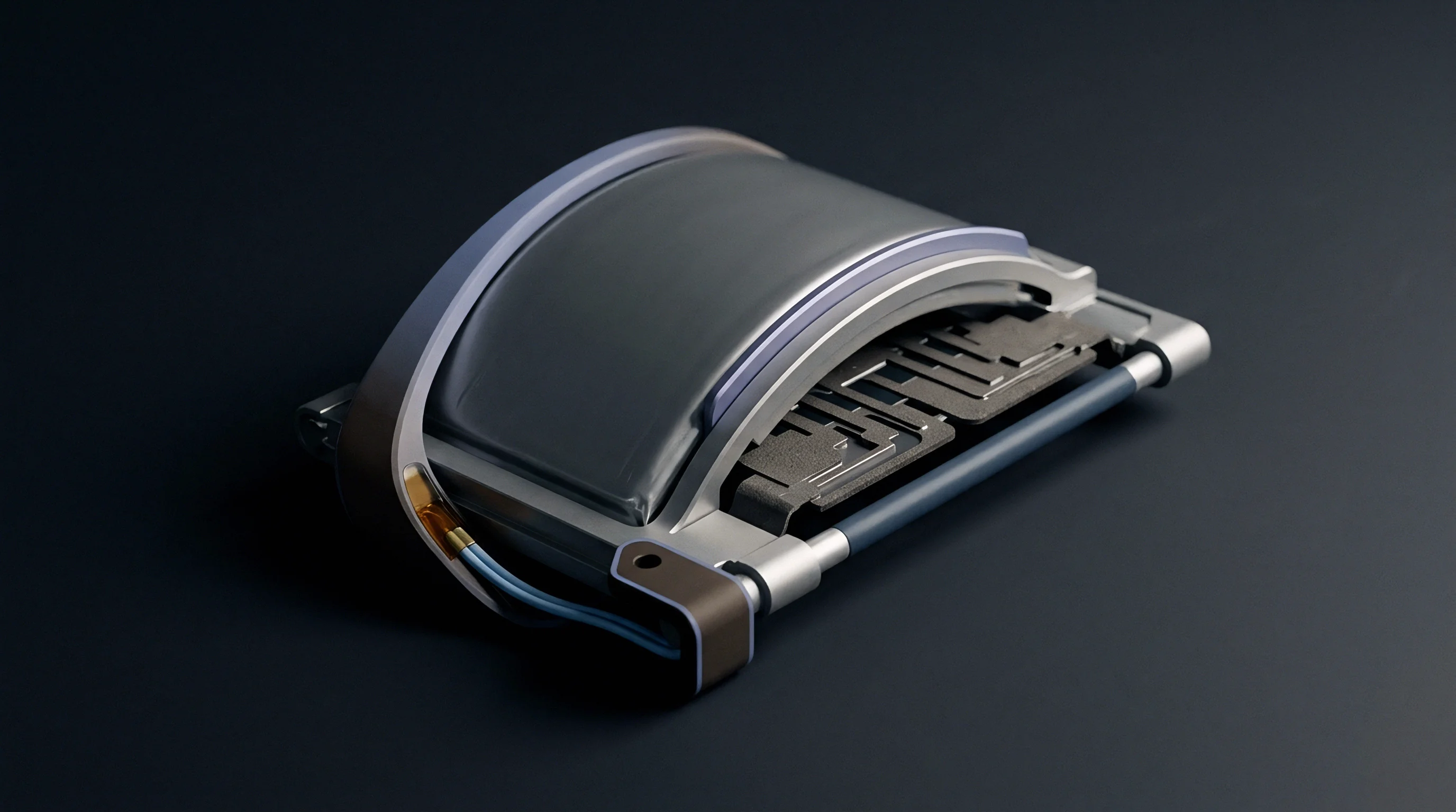
Triaxial fiber Bragg grating sensor rosettes resolve this stress field by arranging three independent grating elements at 0, 45, and 90-degree angles relative to the cell’s longitudinal axis. The planar strain tensor components are calculated directly from wavelength shifts across all three optical nodes.
- Axial strain derivation extracts longitudinal deformation along the electrode current path using the primary grating wavelength response.
- Transverse strain isolation quantifies lateral pouch expansion against side retention rails via the orthogonal grating element.
- Shear strain computation calculates off-axis angular distortion across the pouch surface from the 45-degree intermediate sensor node.
- Temperature correction compensation subtracts thermal baseline drift using an unstrained reference grating housed inside an isolated loose tube.

Can Triaxial FBG Telemetry Survive Electrolyte Exposure?
Polyimide coatings resist the cyclic ester solvents and organic carbonates in commercial lithium-ion cells, whereas acrylate coatings degrade and peel within hours of exposure. Cured at 350 degrees Celsius, polyimide preserves mechanical coupling between the pouch surface and glass core through thousands of microstrain cycles. The efficiency of this adhesive bond determines how accurately measured surface strain reflects internal cell swelling.
| Polymer Coating Material | Layer Thickness | Solvent Resistance Rating | Strain Transfer Efficiency | Maximum Service Limit |
|---|---|---|---|---|
| High-Temperature Polyimide | 15 +/- 2 um | Exceptional | 98.4 % | +300 deg C |
| Dual-Layer Acrylate | 62.5 +/- 5 um | Poor | 89.1 % | +85 deg C |
| Fluoropolymer ETFE | 25 +/- 3 um | High | 92.6 % | +150 deg C |
| ORMOCER Hybrid Ceramic | 10 +/- 1 um | Exceptional | 99.2 % | +200 deg C |
Intercalation strain profiles show distinct slope changes during phase transitions in lithium nickel manganese cobalt oxide cathodes. Fast charging can trigger localized anode overpotentials well before gross terminal voltage flags a problem, allowing triaxial telemetry to catch the mechanical signature of lithium deposition before dendrites pierce the separator.
Structural deflection in the enclosure alters boundary conditions across the cell stack. Rigid aluminum foam or elastomeric silicone compression pads take up part of the volumetric pouch expansion, while the triaxial sensor array measures the balance between raw swelling pressure and enclosure restraint stiffness. This strain tensor gives pack management software a direct physical readout of state-of-charge and state-of-health.
Standard design practice aligns sensor orientation angles with the primary pouch rolling or stacking direction.


Sheath

Protective Sleeving and Mechanical Clamping Interfaces
Unprotected optical fibers break under local pinching loads between adjacent pouch cells. Structural battery packs maintain steady mechanical compression between 0.2 and 0.8 megapascals to prevent electrode delamination and preserve ionic conductivity. Placing a bare fiber directly inside this joint concentrates hundreds of megapascals along a thin line contact, so engineers route sensing fibers inside protective composite carrier tapes or micro-grooved elastomer sheets.
Stainless steel micro-capillaries with 0.5-millimeter outer diameters protect the fiber along inter-cell transit corridors. Across the active pouch area, a micro-molded polyetheretherketone ribbon with recessed channels houses the fiber flush with the ribbon face, distributing compression loads evenly over the pouch surface without crushing the core.
Rigid protective carriers limit localized mechanical point loads on pouch cell surfaces to values below 50 kilopascals under 10 kilonewtons total pack clamping force.
Splicing multiple optical sub-assemblies inside dense pack layouts creates factory line takt challenges. While fusion splicing achieves signal loss below 0.02 decibels per joint, mechanical push-pull connectors offer modular assembly during pack builds. These miniature push-pull connectors must maintain alignment within 0.5 micrometers under the random vibration profiles defined by automotive standards.
- Mechanical ribbon carrier spreads clamping loads over a minimum surface area of twenty square centimeters per sensing node.
- Slotted silicone isolation sheet decouples exterior casing vibrations from the sensitive fiber Bragg grating active region.
- Miniature ruggedized optical terminal secures the cell telemetry harness to the pack management master module.
- Internal strain relief loop absorbs dimensional changes caused by thermal pack expansion without loading optical splices.
Enclosure splice trays must fit service loops with bend radii above twenty millimeters. This extra length allows module replacement during warranty repairs and wraps into dedicated cassette trays next to the main battery disconnection unit.
Passing long-term vibration testing depends on anchoring loose fiber segments with low-outgassing silicone potting adhesives. Left unsecured, fiber lengths oscillate under road shock, causing fatigue fractures at rigid bulkhead transitions.
Standard quality agreements require total optical harness attenuation across the pack to stay under 3.0 decibels over the full warranty service life.

Liability

Warranty Boundaries and Certification Allocation
Adding optical telemetry shifts the legal line between cell supplier performance guarantees and pack integrator responsibilities. Standard cell warranties cover electrical capacity loss, internal impedance growth, and electrolyte containment within set temperature windows. Bonding optical sensor arrays directly to the pouch surface alters local heat dissipation and mechanical pressure profiles, leading cell vendors to void warranties if adhesives induce stress cracking in the aluminium laminate.
Pack integrators bear primary responsibility for regulatory compliance under UN 38.3 transport testing and UN ECE R100 traction battery safety standards. Internal telemetry hardware must meet dielectric isolation requirements above two kilovolts direct current between active high-voltage busbars and chassis ground. Optical fibers naturally meet these dielectric requirements, bypassing the heavy isolation barriers required for copper thermistor harnesses.
The optoelectronic interrogator remains a significant bill-of-materials expense. High-speed interrogators add between 200 and 800 dollars per pack in low-volume prototypes, though custom photonic integrated circuits can pull that cost down toward 40 dollars per pack at production volumes over 100,000 units annually. The choice of interrogator architecture determines whether signal processing happens inside the pack or on an external master controller.
Qualification dossiers must prove that optical feedthroughs maintain enclosure fire barrier integrity during thermal runaway containment testing. Under standard UL 2580 testing, which subjects the enclosure to internal flame jets, polymeric jackets and feedthrough grommets must self-extinguish and preserve containment for at least five minutes to ensure occupant egress time.
Liability between cell supplier and pack assembler remains murky when localized swelling fractures an embedded sensor array without causing electrical failure in the cell.