Electrolyte Solvent Headspace Identification for Battery Seal Integrity Testing
Electrolyte solvent headspace analysis detects micro-leaks down to 1E-8 mbar L/s by quantifying vaporized carbonate signatures from battery seal fissures.
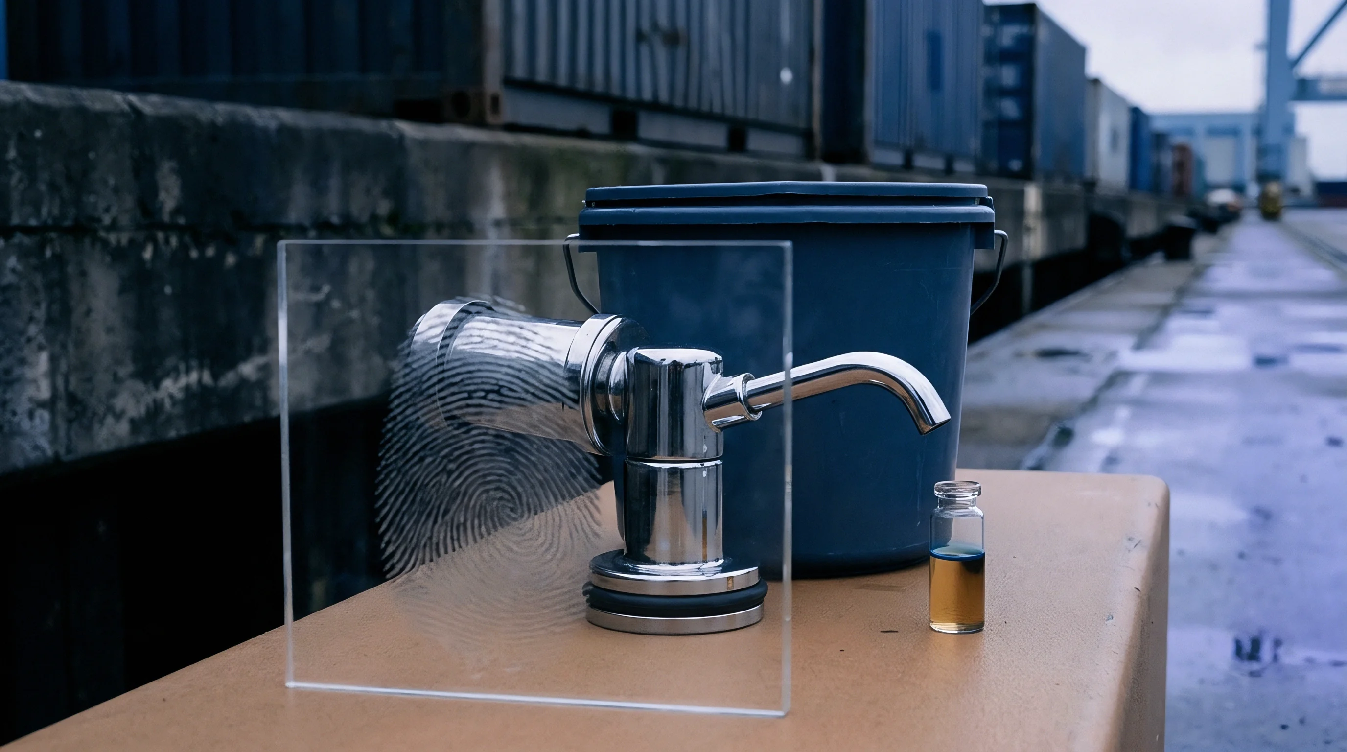

Leakage
Hermetic enclosure failures in lithium-ion cells start at mechanical boundaries: the polymer-to-metal heat seals of pouch packaging, glass-to-metal seals on prismatic feedthroughs, or crimp gaskets on cylindrical cans. When micro-fissures open along these interfaces, internal organic solvents volatilize into the surrounding air. Catching these fugitive solvent molecules inside an enclosed test volume gives direct physical proof of a seal breach long before gross liquid egress or impedance drops show up on incoming inspection benches.
Traditional gross leak testing relies on bath bubble emission or bulk vacuum decay. Helium mass spectrometry offers far higher sensitivity, but it requires pre-fill bombing cycles that risk crushing thin-walled cell cases or contaminating internal chemistry with tracer gas. Electrolyte solvent headspace analysis avoids tracer gas bombing altogether by using the cell’s native chemistry.
Liquid electrolyte formulations blend volatile linear carbonates with cyclic species, creating measurable internal vapor pressures at ambient and elevated inspection temperatures.
Helium mass spectrometry detects leaks down to 1E-9 mbar L/s yet demands pressure bombing cycles that distort pouch cell perimeter seals.
Internal vapor pressure forces volatile solvent molecules through microscopic, tortuous paths across the gasket or polypropylene seal layer. Once these vapors escape the cell boundary, an enclosed sniffing chamber or extraction manifold captures them. Gas chromatography-mass spectrometry (GC-MS) or selective photoionization detectors (PID) then isolate these distinct molecular signatures.
Quantitative headspace evaluation resolves micro-leaks spanning 1E-4 down to 1E-8 mbar L/s, providing an objective baseline for seal integrity assurance.
A failed hermetic boundary lets atmospheric moisture in while electrolyte solvent escapes. Water ingress accelerates the hydrolytic cleavage of lithium hexafluorophosphate into toxic hydrofluoric acid, degrading cathode active materials and driving rapid capacity loss. Headspace solvent detection acts as an early screen, intercepting compromised containment envelopes during manufacturing lot qualification before sub-assemblies head into potting, modular integration, or safety certification testing.
When an incoming lot fails seal verification, detected solvent traces can originate from ambient factory background wash rather than genuine seal breaches.
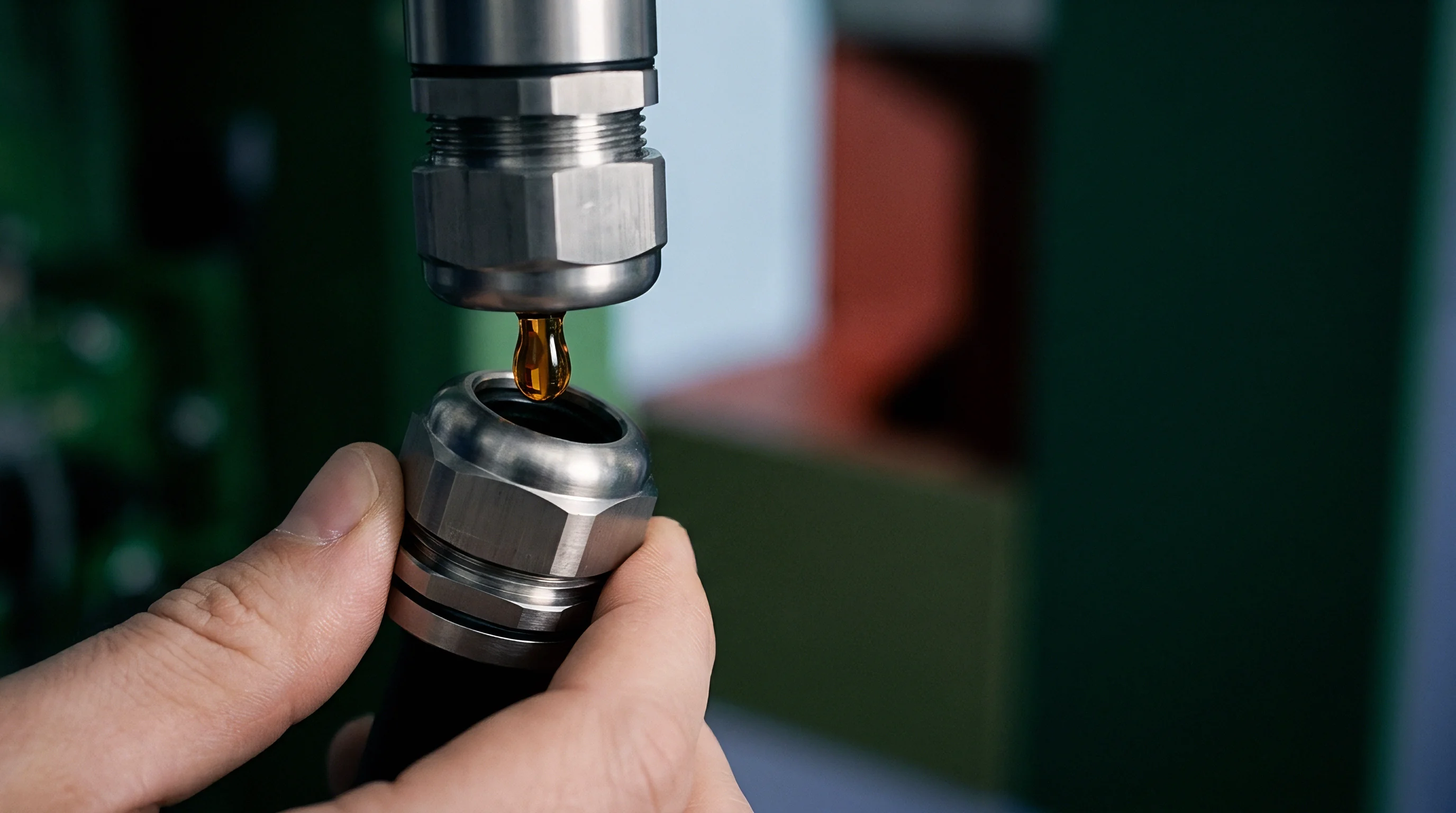
Volatility
Liquid electrolyte systems use balanced mixtures of cyclic carbonates, linear carbonates, and specialized functional additives. The distinct physical constants of these organic solvents dictate how fast they vaporize and their relative abundance in the test chamber headspace. High dielectric permittivity cyclic carbonates, such as ethylene carbonate (EC) and propylene carbonate (PC), have high boiling points and minimal ambient vapor pressures.
Linear carbonates ~ including dimethyl carbonate (DMC), ethyl methyl carbonate (EMC), and diethyl carbonate (DEC) ~ possess low boiling points and elevated partial pressures, dominating the vapor distribution above the cell interface.
Equilibrium vapor pressure for individual solvent constituents follows Antoine equation relationships across standard inspection temperatures. Raising the test chamber temperature from 25 °C to 60 °C amplifies the volatility of linear carbonates by an order of magnitude. This thermal acceleration increases mass flux across micro-capillary defects without inducing thermal runaway or rupturing internal pressure relief vents.
| Solvent Component | Molecular Weight (g/mol) | Boiling Point (°C) | Vapor Pressure at 20 °C (kPa) | Dynamic Viscosity at 25 °C (mPa·s) | Primary MS Quant Ion (m/z) |
|---|---|---|---|---|---|
| Dimethyl Carbonate (DMC) | 90.08 | 90.1 | 5.60 | 0.59 | 45, 59, 90 |
| Ethyl Methyl Carbonate (EMC) | 104.10 | 107.5 | 3.60 | 0.65 | 45, 59, 75 |
| Diethyl Carbonate (DEC) | 118.13 | 126.8 | 1.40 | 0.75 | 45, 63, 91 |
| Ethylene Carbonate (EC) | 88.06 | 248.0 | 0.01 | 1.90 | 43, 88 |
| Propylene Carbonate (PC) | 102.09 | 242.0 | 0.04 | 2.53 | 43, 58, 102 |
Dimethyl carbonate gives the highest sensitivity for headspace gas analysis because of its 5.60 kPa vapor pressure at standard temperature. When a formulation lacks DMC, ethyl methyl carbonate acts as the primary volatile marker. Knowing baseline solvent blend ratios allows accurate calibration of mass spectrometer transfer lines and detector gain settings.
Calibrating the instrument against slow-evaporating ethylene carbonate underestimates total fugitive emissions by failing to account for the faster diffusion of linear species.
Vapor pressures of linear carbonates exceed cyclic carbonate volatility by more than two orders of magnitude at ambient testing temperatures.
Fugitive solvent transport through micro-fissures falls into three fluid dynamic regimes: viscous laminar flow, transition flow, and molecular effusion (Knudsen diffusion). Which transport mode governs flow depends directly on the ratio between the mean free path of the carbonate vapor and the hydraulic diameter of the seal fissure. In ultra-fine micro-fissures below 0.5 micrometers, molecular effusion dominates, sending light, low-viscosity species through at rates inversely proportional to the square root of their molecular weights.
A solid seal assessment framework leverages these transport differences to distinguish surface contamination from through-hole capillary leakage. Surface contamination releases residual solvent across all volatile fractions within seconds of chamber evacuation. Capillary leakage produces a continuous, sustained concentration rise matching theoretical gas diffusion kinetics over multi-minute accumulation cycles.
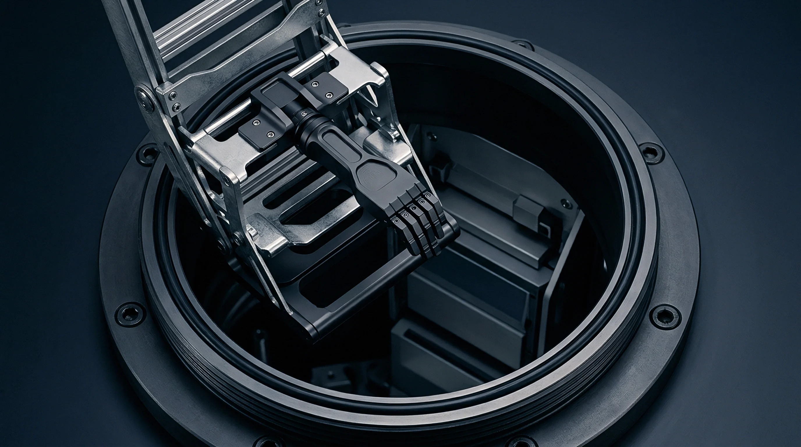
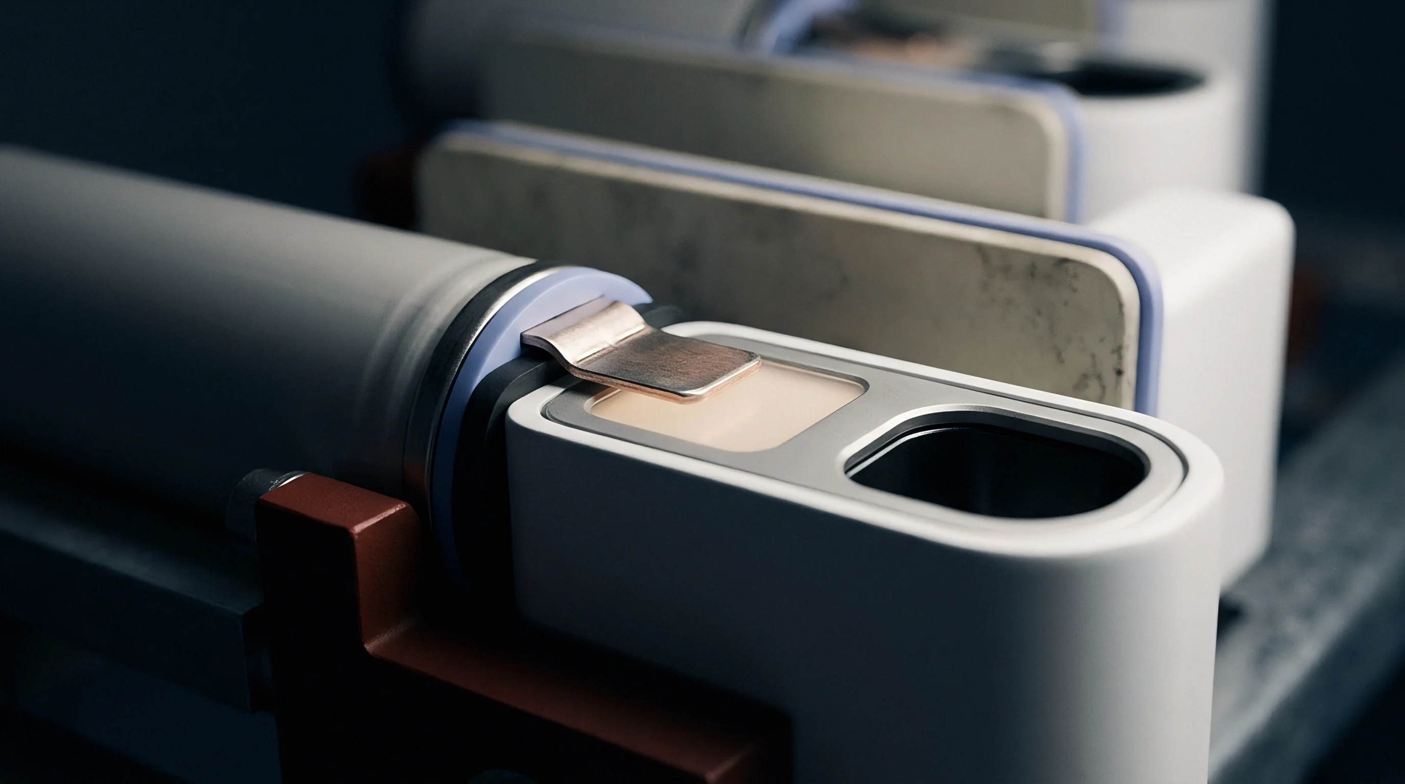
Sampling
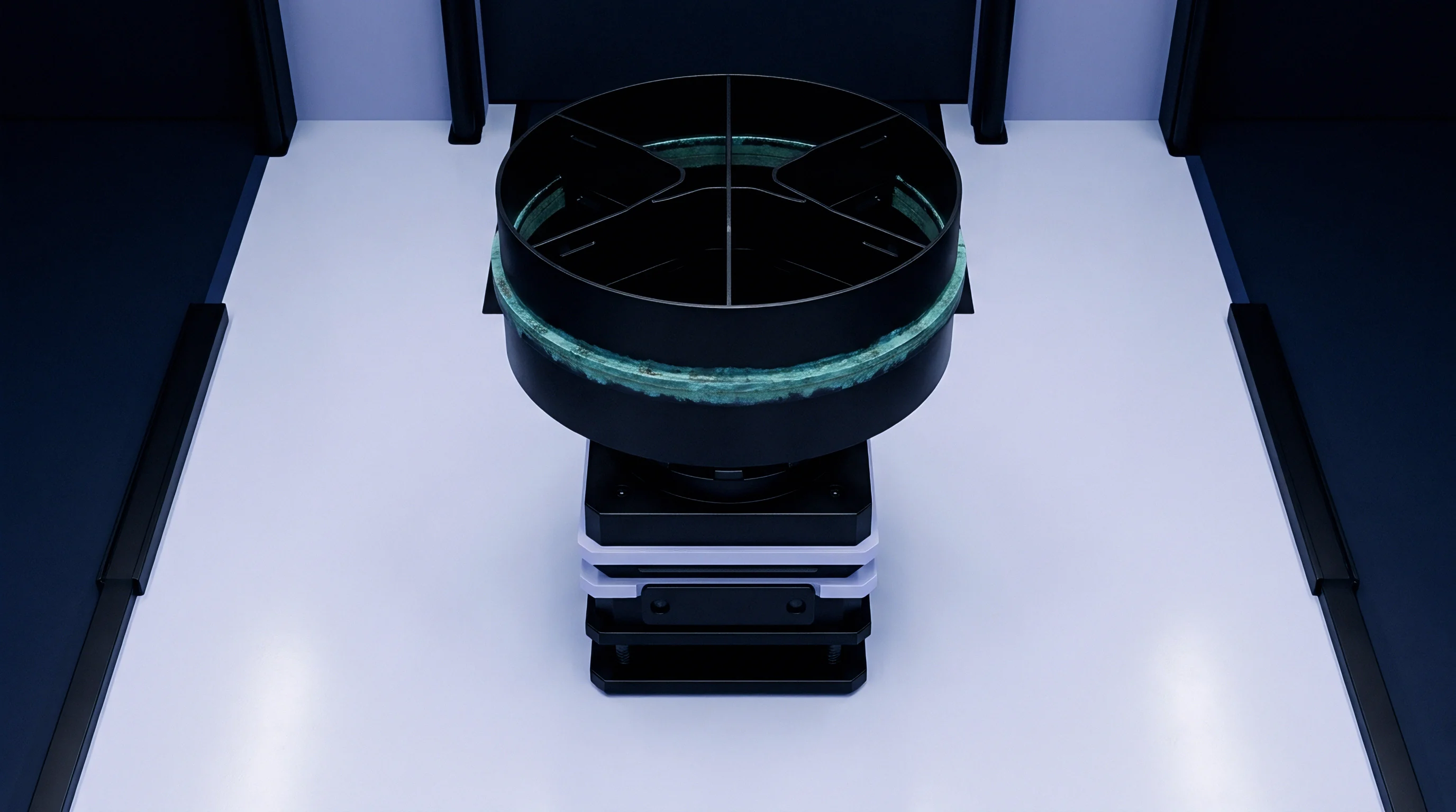
Quantifying seal leakage accurately requires structured headspace extraction and sample preparation protocols. Cells are tested inside sealed chambers constructed from passivated stainless steel or fluoropolymer-lined vessels to suppress background hydrocarbon outgassing. The test volume must stay minimized relative to cell displacement volume, maintaining maximum vapor concentration per unit of time for a given leak rate.

Chamber Design and Thermal Conditioning
The sample enclosure uses precision heating jackets that maintain isothermal conditions from 20 °C to 65 °C within a 0.5 °C tolerance band. Raising the chamber temperature accelerates solvent volatilization, converting sub-ppm leak rates into clear analytical peaks. Pre-conditioning cycles pull a roughing vacuum down to 100 Pa for 60 seconds to strip external tooling contamination, followed by dry nitrogen backfilling to atmospheric pressure before accumulation begins.
Extraction Techniques and Interface Plumbing
Transfer lines between the testing vessel and analytical column need continuous heat tracing above 120 °C. Unheated cold spots along transfer tubing condense high-boiling carbonate fractions, leading to analytical carryover and false positives on subsequent tests. Solid-Phase Microextraction (SPME) and direct loop injection serve as the two primary sampling interfaces.
- Direct Gas Sampling Valves inject fixed aliquot volumes directly into the analytical carrier gas stream without phase change delays, enabling automated testing cycles under 180 seconds.
- Solid Phase Microextraction Fibers coated with divinylbenzene and carboxen stationary phases concentrate ultra-trace solvent vapors over extended collection intervals, resolving leak rates below 1E-8 mbar L/s.
- Thermal Desorption Tubes packed with Tenax TA adsorbents trap high-volume purge exhausts from multi-cell qualification batches for centralized laboratory desorber analysis.
- Dynamic Purge Manifolds sweep continuous zero-grade nitrogen across the cell seal perimeter into a dedicated photoionization detector cell for real-time fissure localization.
Static accumulation protocols seal the cell within the test chamber for a fixed dwell time, typically 300 to 900 seconds, before drawing the accumulated headspace gas into a calibrated sample loop. Dynamic sniffing configurations draw continuous carrier gas over the cell perimeter at a controlled flow rate, measuring steady-state concentration differences between inlet and outlet gas paths. Dynamic methods shorten cycle times, while static accumulation maximizes analytical sensitivity for stringent lot qualification requirements.
Underestimating carrier gas flow in dynamic sniffing arrangements dilutes solvent concentrations below detector sensitivity thresholds, resulting in false-negative seal clearance certificates.


Spectrometry
Gas chromatography coupled with mass spectrometry (GC-MS) is the reference technique for separating genuine battery seal breaches from external manufacturing contamination. The chromatographic column separates solvent components over time by boiling point and polarity, while the mass spectrometer breaks each eluting compound into characteristic ionization fragments for unambiguous identification.
Electron ionization (EI) at 70 eV fragments linear and cyclic carbonates into specific mass-to-charge (m/z) ratios. Selected Ion Monitoring (SIM) mode targets high-abundance diagnostic ions, boosting signal-to-noise ratios by a factor of 50 compared to full-spectrum scanning modes. For dimethyl carbonate, monitoring m/z 45 (dimethyl ether fragment), m/z 59 (carboxymethyl fragment), and the molecular ion m/z 90 provides robust quantification alongside structural confirmation.
Ethyl methyl carbonate yields primary quantifier ions at m/z 45, 59, and 75, while diethyl carbonate confirms at m/z 45, 63, and 91.
Selected Ion Monitoring mode elevates analytical sensitivity fiftyfold by tracking specific carbonate fragmentation masses rather than scanning full spectra.
To quantify physical leak rates from raw mass spectrometry signal areas, the laboratory builds five-point calibration curves using certified reference gas standards or gravimetrically calibrated liquid solvent micro-injections. Measured peak area converts to total moles of accumulated solvent vapor within the enclosure volume over time. Converting mass flux into standardized leak rate units (mbar L/s) requires applying the ideal gas law alongside compound-specific vapor pressure corrections.

Worked Construction of Headspace Leak Rate Calculation
Assumptions: A 50 Ah automotive pouch cell is tested inside an enclosed chamber with a net free headspace volume (V) of 0.250 liters at a regulated temperature (T) of 313.15 K (40 °C). The static accumulation dwell time (t) is 600 seconds. Quantitative GC-MS analysis reveals an accumulated dimethyl carbonate (DMC) mass of 1.20 micrograms within the chamber headspace.
The background baseline DMC level is 0.05 micrograms. The universal gas constant (R) is 8.314 J/(mol·K), and the molar mass of DMC (M) is 90.08 g/mol.
- Net Mass Calculation subtracts baseline background contamination from the total detected analyte mass: Net Mass = 1.20 ug – 0.05 ug = 1.15 ug = 1.15E-6 g.
- Molar Accumulation Determination converts the net analyte mass into molar quantity using the compound molar mass: n = (1.15E-6 g) / (90.08 g/mol) = 1.277E-8 mol.
- Partial Pressure Resolution applies the ideal gas equation to compute the internal vapor pressure generated within the free volume: P = (n R T) / V = (1.277E-8 mol 8.314 J/(mol·K) 313.15 K) / (0.00025 m3) = 0.1331 Pa = 1.331E-3 mbar.
- Standardized Leak Rate Derivation divides the pressure-volume product by the accumulation interval to express the final hermetic integrity value: Q = (P V) / t = (1.331E-3 mbar 0.250 L) / 600 s = 5.55E-7 mbar L/s.
This calculated leak rate of 5.55E-7 mbar L/s indicates an active capillary micro-fissure within the pouch cell heat seal seam. While this value permits the cell to pass gross bubble immersion tests, it exceeds the standard automotive hermeticity threshold of 1.0E-6 mbar L/s when evaluated across long-term service life projections.
Variations in carrier gas linear velocity across the chromatographic column can shift retention times by several seconds, misidentifying trace additive peaks as linear carbonate markers.

Screening
High-volume manufacturing lines require rapid screening tools that complement laboratory-grade GC-MS validation. Production facilities deploy continuous sniffing tunnels, photoionization detectors (PID), flame ionization detectors (FID), and non-dispersive infrared (NDIR) sensors to process incoming cell lots at high throughput.
| Technology | Detection Limit (mbar L/s) | Cycle Time per Cell | Speciation Capability | Capital Cost per Unit | Maintenance Requirement |
|---|---|---|---|---|---|
| GC-MS (SIM Mode) | 1E-8 | 5 to 15 min | Absolute (Compound Identification) | High ($120k – $250k) | High (Column bake-out, vacuum pump service) |
| Photoionization (PID, 10.6 eV) | 5E-6 | 5 to 15 s | Total VOC Only | Low ($5k – $15k) | Moderate (Lamp cleaning, regular calibration) |
| Flame Ionization (FID) | 1E-6 | 3 to 10 s | Total Hydrocarbon Only | Moderate ($20k – $45k) | Moderate (Burner cleaning, fuel gas supply) |
| NDIR (Carbonate Specific) | 1E-5 | 2 to 8 s | Functional Group Only | Moderate ($15k – $30k) | Low (Optical path alignment, zero baseline check) |
| Helium Mass Spectrometry | 1E-9 | 30 to 60 s | Tracer Gas Specific | High ($80k – $160k) | High (Filament replacement, bombing chambers) |
Photoionization detectors equipped with 10.6 eV ultraviolet discharge lamps ionize organic carbonate vapors without ionizing ambient nitrogen, oxygen, or water vapor. The ionization potentials of dimethyl carbonate (10.50 eV), ethyl methyl carbonate (10.35 eV), and diethyl carbonate (10.15 eV) fall just below the 10.6 eV photon energy threshold. Cyclic carbonates like ethylene carbonate possess higher ionization thresholds (10.80 eV), remaining undetected by standard 10.6 eV PID lamps.
Standard 10.6 eV photoionization lamps selectively ionize linear carbonates while remaining completely blind to atmospheric background gases.
Production screening systems balance false-rejection risk against escape probability by establishing dynamic detection thresholds based on running statistical process averages. Automated test stations clear cells showing headspace signals within three standard deviations of the baseline, shunting intermediate outliers to secondary GC-MS verification benches.
High ambient humidity causes signal quenching inside photoionization chambers, depressing perceived leak readings and masking active seal defects.
Conformity
Transport classification and safety mandates enforce strict non-leakage criteria across international shipping corridors. The UN Manual of Tests and Criteria, Part III, subsection 38.3, imposes eight stress sequences, designated T.1 through T.8. Tests T.1 (Altitude Simulation), T.2 (Thermal Cycling), and T.5 (External Short Circuit) directly stress internal cell pressures and mechanical seal boundaries.
The regulatory pass criterion across UN 38.3 demands no leakage, no venting, no disassembly, no rupture, and no fire.
Standard certification bodies verify non-leakage primarily through pre-test and post-test gross mass measurements. Precision analytical balances register mass loss across the test sequence, with pass thresholds set at total mass loss not exceeding 0.1% for large cells and 0.5% for small cells. This gravimetric threshold represents a significant regulatory gap: a 0.1% mass loss on a 50 Ah cell carrying 120 grams of liquid electrolyte corresponds to a massive 120-milligram solvent release, masking micro-capillary leaks that release only micrograms of fugitive vapor.
| Standard / Document | Applicable Clause | Prescribed Leakage Assessment Method | Resolution Limit | Operational Risk Level |
|---|---|---|---|---|
| UN Manual of Tests and Criteria 38.3 | Table 38.3.4.1 (T.1 to T.5) | Gravimetric Mass Balance (0.1% limit) | 0.01 g to 0.1 g | High (Permits severe micro-fissure escape) |
| IEC 62133-2 | Clause 7.3.2 (Thermal Abuse) | Visual Inspection, Mass Measurement | Visual droplet level | High (Fails to capture early vapor releases) |
| UL 1642 | Section 10 (Heat Test) | Visual Inspection for Venting / Rupture | Gross rupture level | Critical (Gross mechanical failure screen only) |
| EU Battery Regulation 2023/1542 | Article 10 / Annex VIII | Quality Management Verification Audit | Defined by Manufacturer | Moderate (Shifts liability directly to importer) |
| SAE J2464 | Section 4.3 (Thermal Shock) | Mass Balance, Chemical Sniffing Option | 1E-4 to 1E-6 mbar L/s | Low (Validates true hermetic boundary) |
Under EU Battery Regulation 2023/1542, the Importer of Record assumes full legal and financial liability for batteries placed on the market. If an imported cell lot passes factory visual checks but carries latent perimeter micro-leaks, atmospheric moisture ingress will degrade the cells within six to eighteen months of field operation. Resulting swelling, high internal resistance, and thermal events fall squarely on the compliance dossier held by the importer.
Receiving inspection engineers close this liability gap by introducing mandatory headspace GC-MS lot sampling into purchase specifications. Applying headspace screening to one cell per thousand incoming units catches seal degradation before modules are assembled, preserving clear recourse against upstream cell manufacturers under international commercial contracts.
Without explicit chemical headspace leak limits in procurement contracts, micro-leaking cells can still pass by showing nominal compliance with crude UN 38.3 gravimetric thresholds.