Correlation of Helium Equivalent Leak Rates to Organic Solvent Vapor Outgassing Kinetics in Pouch Cells
Helium leak rates overstate organic solvent vapor outgassing by orders of magnitude due to Knudsen flow transitions and lower internal solvent partial pressures.

Seam
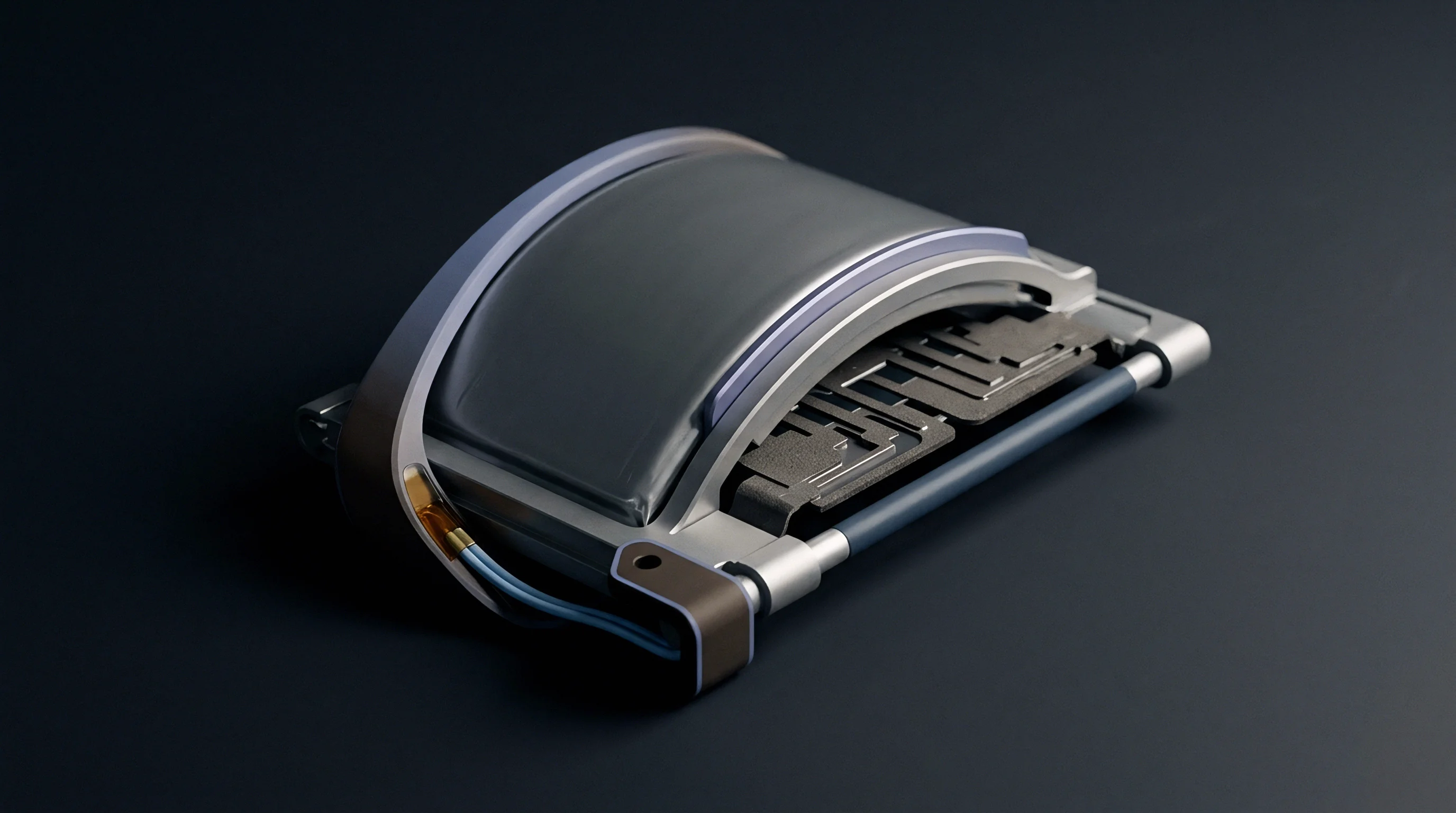
Laminated aluminum pouch films rely on a polyolefin inner seal ~ usually cast polypropylene or modified polyethylene ~ to isolate volatile organic liquid electrolytes from moisture and air. Heat and clamping pressure melt these opposing polyolefin faces together during pack assembly to form the primary seal. Even so, microscopic channels inside the bonded zone leave permanent pathways for light gas tracers like helium and liquid solvent vapors to migrate.
Sub-micron voids persist along the heat-seal interface, driven by uneven thermode pressure, polymer contraction during crystallization, and electrolyte spatter during high-speed cell filling.
Pouch cells leak across seals.
The geometry of a leak path determines how fluid species move through the seal boundary. Narrow capillary channels between ten nanometers and several micrometers in hydrodynamic diameter run the full width of the seal, from the wet internal cavity to the outside air. Heat sealing routinely leaves these micro-cavity channels behind.
During production testing, quality control routines pressurize or bombard the pouch with helium gas to measure tracer flow rates. Projecting those short-term tracer figures into ten-year electrolyte mass loss requires a detailed look at the polyolefin seal channel geometry.
| Defect Category | Typical Defect Width (nm) | Dominant Transport Mechanism | Helium Equivalent Leak Rate (mbar L/s) | Organic Solvent Outgassing Flux (g/year) |
|---|---|---|---|---|
| Polymer Crystallite Boundary Void | 10 to 50 | Pure Knudsen Molecular Flow | 1.0E-08 to 5.0E-07 | 1.2E-05 to 6.0E-04 |
| Thermode Pressure Misalignment Channel | 50 to 500 | Knudsen-Viscous Transition Flow | 5.0E-07 to 1.0E-05 | 6.0E-04 to 2.5E-02 |
| Electrolyte Spatter Infiltration Cavity | 500 to 5000 | Viscous Poiseuille Laminar Flow | 1.0E-05 to 1.0E-03 | 2.5E-02 to 1.8E+00 |
| Pinhole Defect in Aluminum Foil Lamination | 100 to 2000 | Mixed Capillary and Knudsen Flow | 1.0E-06 to 5.0E-04 | 1.5E-03 to 8.0E-01 |
Solvent molecules in lithium-ion pouch cells consist primarily of volatile alkyl carbonates like dimethyl carbonate, ethyl methyl carbonate, and diethyl carbonate, alongside cyclic species such as ethylene carbonate and propylene carbonate. Liquid electrolyte rests directly against the inner seal faces. The kinetic energy and molecular cross-section of these organic species differ sharply from elemental helium; helium has a kinetic diameter of roughly 0.26 nanometers, while linear alkyl carbonates span 0.55 to 0.85 nanometers.
A physical channel that allows rapid, ballistic passage of helium atoms imposes severe spatial and steric constraints on larger organic vapors.
Polymers absorb organic solvent vapors, swelling localized areas along the inner seal perimeter. As linear alkyl carbonates diffuse into the cast polypropylene layer, polymer chain relaxation expands the matrix. This swelling alters micro-channel hydrodynamic diameters, narrowing fine capillary pathways while plasticizing the surrounding polyolefin chains.
Helium tracer testing relies on a dry, non-interacting gas that passes through channels without modifying the substrate. Organic solvent vapors interact directly with the matrix, producing time-dependent transport rates that evolve until the seal reaches chemical equilibrium with internal cell vapors.
A dry gas tracer ignores polymer matrix swelling that dynamic solvent vapor exposure induces.
Sealing pouch cells requires uniform heat transfer across multi-layer aluminum laminate foils. Outer protective polyamide layers, middle aluminum barrier foils, and inner polyolefin seal layers all carry different thermal conductivities and thermal expansion coefficients. Thermode pressure drops at corners and step-downs where tab leads exit the pouch body create vulnerable spots.
At tab seal junctions, the polyolefin film must deform around metallic current collector leads coated with functional sealant resins. Microscopic gaps at these interfaces leave tortuous leak paths where organic solvent vapors outgas during extended storage.
Pouches showing zero detectable helium leak rate during assembly line testing frequently experience significant weight loss during accelerated high-temperature shelf life evaluations. Helium molecular tracer testing is often treated as an absolute, conservative upper bound for seal integrity, but that assumption treats helium gas flow and organic solvent outgassing as simple scalar multiples of molecular speed. Real polyolefin seal channels introduce surface sorption, capillary condensation, and pressure-dependent flow transitions that break simple scalar equivalence.

Physics
Modeling gas and vapor transport through pouch seal channels begins with fluid dynamics in micro-geometries. Characterizing flow through a micro-channel requires calculating the Knudsen number ~ the ratio of the molecular mean free path to the characteristic physical diameter of the channel. Mean free path depends on gas temperature, absolute pressure, and collision cross-section.
When the Knudsen number exceeds 10, gas molecules collide far more frequently with channel walls than with each other, putting fluid movement into the Knudsen molecular flow regime. When the Knudsen number falls below 0.01, intermolecular collisions dominate, creating continuum viscous Poiseuille flow. The region between 0.01 and 10 represents transitional flow.
Pure helium diffuses faster than solvents.
Under Knudsen molecular flow conditions, the volumetric leak rate of a gas driven by a pressure differential through a circular channel scales inversely with the square root of its molar mass. Molecular weight dictates Knudsen flow rates: helium has a molar mass of 4.00 grams per mole, dimethyl carbonate is 90.08 grams per mole, and ethyl methyl carbonate is 104.10 grams per mole. For an identical pressure gradient across a narrow channel operating in the Knudsen regime, the molar flow rate ratio between dimethyl carbonate vapor and helium tracer gas calculates strictly as the square root of four divided by 90.08, yielding a conversion factor of approximately 0.210.

Fluid Transport Equations across Boundary Regimes
Calculating mass outgassing rates demands accurate mathematical descriptions for both viscous and molecular transport limits. In the continuum viscous regime, Poiseuille flow governs gas flux. The molar flow rate Q_viscous of a gas through a cylindrical micro-channel of diameter d and length L under inlet pressure P_in and outlet pressure P_out follows the relationship:
Q_viscous = (pi d^4 / (256 eta R T L)) (P_in^2 – P_out^2)
Here, eta represents dynamic viscosity, R stands for the universal gas constant, and T represents absolute temperature. Dynamic viscosity for helium gas at 298 Kelvin equals 1.98E-05 Pascal-seconds. The vapor phase dynamic viscosity of dimethyl carbonate under similar ambient conditions equals approximately 0.95E-05 Pascal-seconds.
In the continuum viscous regime, lower solvent vapor viscosity partially offsets the molar mass disadvantage, accelerating solvent flow relative to helium when driving pressure differentials remain large.
When channel dimensions drop below 100 nanometers, Knudsen flow dominates completely. The molar flow rate Q_Knudsen under molecular flow conditions scales according to the following equation:
Q_Knudsen = (1 / 6) sqrt(2 pi / (M R T)) (d^3 / L) (P_in – P_out)
In this equation, M represents the molar mass of the migrating chemical species. Notice that Knudsen molecular flow depends upon the linear pressure difference rather than the difference of squared pressures seen in viscous continuum flow. The transition between these two analytical equations requires a unified flow equation proposed by Knudsen, incorporating a transitional correction factor dependent on average channel pressure.
Worked Example Converting Tracer Flow to Annual Solvent Mass Loss
Consider a pouch cell exhibiting a measured helium equivalent leak rate Q_He of 1.00E-06 mbar L/s during high-vacuum chamber testing. The test protocol applies a pure helium overpressure of 1.00 bar inside the test chamber while evacuating the external space to near-zero pressure, yielding a helium pressure differential Delta P_He equal to 1.00 bar (100,000 Pascals).
Converting this helium reading to organic solvent mass loss requires determining the internal partial vapor pressure of volatile carbonates inside a fully charged cell at 25 degrees Celsius. Ethylene carbonate has a negligible vapor pressure of roughly 0.002 mbar. Dimethyl carbonate exhibits a saturated vapor pressure P_DMC of 72.0 mbar (7,200 Pascals) at 25 degrees Celsius, while ethyl methyl carbonate exhibits a vapor pressure P_EMC of 36.0 mbar (3,600 Pascals).
The total internal solvent vapor driving pressure Delta P_solvent venting into open ambient air (zero ambient solvent partial pressure) equals approximately 72.0 mbar, assuming dimethyl carbonate dominates the headspace vapor phase.
Assume the leak channel diameter measures 40 nanometers, placing gas transport firmly within the Knudsen molecular flow regime. First, convert the measured helium leak rate from volumetric vacuum units to molar flow rate n_dot_He:
n_dot_He = Q_He / (R T) = (1.00E-06 mbar L/s 100 Pa/mbar 1.00E-03 m^3/L) / (8.314 J/mol K 298.15 K) = 4.034E-11 mol/s
Next, apply the Knudsen molecular mass correction factor alongside the partial pressure differential ratio between helium test conditions and internal solvent equilibrium vapor pressure:
n_dot_DMC = n_dot_He sqrt(M_He / M_DMC) (Delta P_DMC / Delta P_He)
n_dot_DMC = 4.034E-11 mol/s sqrt(4.003 / 90.08) (72.0 mbar / 1000.0 mbar)
n_dot_DMC = 4.034E-11 0.2107 0.0720 = 6.120E-13 mol/s
To obtain annual mass loss m_loss in grams per year, multiply n_dot_DMC by the molar mass of dimethyl carbonate and total seconds in one year (31,536,000 seconds):
m_loss = 6.120E-13 mol/s 90.08 g/mol 31,536,000 s/year = 1.738E-03 g/year
A helium tracer leak rate of 1.00E-06 mbar L/s measured under 1 bar helium differential corresponds to a dimethyl carbonate outgassing rate of approximately 1.74 milligrams per year when stored at 25 degrees Celsius under molecular flow conditions.
Calculated solvent vapor outgassing under Knudsen flow yields 1.74 milligrams per year for a helium tracer reading of 1.00E-06 mbar L/s at room temperature.
If the micro-channel defect broadens to 2.0 micrometers, viscous Poiseuille flow takes over. Under viscous conditions, solvent outgassing scales with squared pressure differences and inverse dynamic viscosities:
Q_ratio_viscous = (eta_He / eta_DMC) ((P_in_DMC^2 – P_out^2) / (P_in_He^2 – P_out^2))
Q_ratio_viscous = (1.98E-05 / 0.95E-05) ((72.0^2 – 0) / (1000.0^2 – 0)) = 2.084 0.005184 = 0.0108
Applying this viscous flow ratio to the same initial baseline helium leak reading increases relative mass loss because viscous transport scales more aggressively with channel radius than molecular flow does. The ratio between helium tracer metrics and solvent loss relies entirely on knowing channel dimensions.
The following structural regimes govern solvent transport across pouch seal layers:
- Viscous Laminar Transport occurs in channels larger than one micrometer where fluid pressure squared differentials dominate flow rates.
- Knudsen Molecular Transport occurs in micro-channels smaller than fifty nanometers where molecular weight square roots dictate ballistic passage.
- Transitional Slip Transport occurs in channels between fifty nanometers and one micrometer where combined viscous and ballistic terms operate simultaneously.
- Capillary Liquid Creep occurs when liquid electrolyte wets channel inner walls, causing liquid phase transport prior to vapor phase flashing at the outer seal exit.
Solvent loss calculations rely on scaling pressure differentials across Knudsen flow regimes. What remains unsettled in physical testing is whether localized condensation inside tortuous micro-channels forms liquid bridges that block gas transport entirely or accelerate solvent mass loss through liquid capillary action.


Kinetics
Solvent outgassing kinetics depend directly on internal temperature, liquid electrolyte vapor pressure, and polyolefin matrix solubility. Raising ambient storage temperature from 25 degrees Celsius to 60 degrees Celsius drastically shifts internal partial pressures; dimethyl carbonate vapor pressure jumps from 72 mbar at 25 degrees Celsius to over 380 mbar at 60 degrees Celsius. Solvent outgassing degrades cell service life.
This non-linear surge in driving pressure accelerates outgassing far faster than simple thermal gas expansion equations predict.
Pressure differentials drive vapor transport.

Can Helium Tracer Testing Predict Long Term Electrolyte Mass Loss?
Tracer testing evaluates baseline mechanical channel integrity, but it cannot forecast time-dependent chemical interactions inside the seal. Polyolefin films absorb organic solvents over prolonged storage, establishing a concentration gradient across the seal width. Solvents dissolve into the polymer matrix at the inner edge, diffuse through the bulk plastic, and desorb into ambient atmosphere at the outer seal perimeter.
This process ~ perm-selectivity transport ~ operates parallel to direct channel leaks. Standard helium testing measures instant leakage through dry voids, missing solution-diffusion transport across the bulk polymer.
Permeation through bulk polyolefin plastic adds a continuous diffusion mass loss that helium tracer vacuum tests cannot detect.
To accurately measure outgassing kinetics and separate bulk film permeation from discrete channel leakage, test engineers apply gas chromatography mass spectrometry coupled with precision cell mass tracking. The following procedure isolates mechanical leak outgassing from solution-diffusion film losses:
- Position the pristine sealed pouch cell inside a sealed glass test chamber maintained at a constant 40 degrees Celsius temperature.
- Sweep the chamber enclosure continuously with ultra-high purity nitrogen carrier gas flowing at exactly 50 standard cubic centimeters per minute.
- Direct the outgoing carrier gas stream through a cryogenic cold trap cooled to minus 80 degrees Celsius for an accumulation interval of four hours.
- A thermal desorption unit rapidly heats the trap to 250 degrees Celsius, injecting trapped solvent vapors into a capillary gas chromatography column.
- Quantify individual mass spectra peaks corresponding to dimethyl carbonate, ethyl methyl carbonate, and diethyl carbonate against calibrated baseline standards.
- Repeat sweep sampling at 24-hour intervals over a total test window of 336 hours to plot mass loss rate against time.
- Compare steady-state outgassing kinetics against initial helium tracer vacuum measurements to isolate channel transport from bulk polymer diffusion.
Outgassing kinetic curves show an initial delay while solvent saturates the dry inner seal face. During this lag ~ typically 48 to 120 hours depending on polyolefin thickness and temperature ~ minimal solvent reaches the exterior pouch edge. Once the polymer matrix reaches saturation equilibrium, outgassing settles into a steady-state linear mass loss regime.
Quality control helium testing, performed right after seal formation during assembly and finished in under thirty seconds, captures physical micro-cavities before electrolyte saturation occurs.
Electrolyte depletion alters cell chemistry long before complete dry-out happens. Losing low-viscosity linear carbonate solvents increases dynamic viscosity and lowers ionic conductivity. As dimethyl carbonate and ethyl methyl carbonate preferentially outgas due to high vapor pressures, the relative concentration of ethylene carbonate and conductive lithium hexafluorophosphate salt rises inside the cell.
That higher salt concentration elevates electrolyte freezing points, accelerates lithium plating during fast charging, and increases internal ohmic resistance.
A helpful rule of thumb states that doubling internal solvent partial pressure doubles molecular outgassing flux through micro-channels while high-temperature polyolefin matrix swelling reduces physical channel diameter.

Bench
Factory leak detection relies on automated vacuum chamber helium mass spectrometry to maintain fast cycle times on high-volume production lines. Fully assembled pouch cells pass into a sealed chamber that evacuates down to typical test pressures between 0.1 and 1.0 mbar. The system injects helium tracer gas either by pre-charging the pouch cavity before final seal closure or by bombing the sealed cell inside a high-pressure helium vessel.
High-sensitivity mass spectrometers tuned to helium atomic mass 4.0026 detect tracer gas escaping through micro-defects.
Vacuum chamber background suppression is critical.
Helium bombing techniques introduce serious quantification errors when applied to flexible pouch cells. Subjecting a sealed pouch to external helium pressures between 2.0 and 5.0 bar forces the gas against the flexible laminate, where it diffuses into outer polyamide skin layers and collects in tiny surface wrinkles along heat-seal edges. When the cell transfers to the vacuum chamber, this adsorbed helium desorbs rapidly into the chamber volume, generating false positive signals that mask genuine seal channel leakage.
| Testing Methodology | Minimum Detectable Leak Rate (mbar L/s) | Cycle Duration Per Unit | Quantification Accuracy | Primary Industrial Limitation |
|---|---|---|---|---|
| Direct Vacuum Chamber Helium MS | 1.0E-09 | 12 to 20 seconds | High (+/- 5%) | Requires tracer injection before final seal |
| Helium Bombing Vacuum Chamber | 5.0E-07 | 45 to 90 seconds | Moderate (+/- 25%) | False positives from surface adsorption |
| Accumulation Chamber Sniffer MS | 1.0E-05 | 30 to 60 seconds | Low (+/- 40%) | Sensitive to ambient air draft currents |
| Organic Solvent Vapor Sniffer MS | 1.0E-07 | 25 to 45 seconds | High (+/- 10%) | Requires thermal activation of cell pouch |
| Differential Vacuum Pressure Decay | 1.0E-03 | 5 to 10 seconds | Very Low (+/- 60%) | Incapable of detecting micro-channel leaks |
Alternative direct solvent outgassing detection utilizes mass spectrometry sniffer probes tuned to specific fragment ions of dimethyl carbonate (mass-to-charge ratios m/z 59 and m/z 90). The test system heats the pouch cell to 45 degrees Celsius inside a closed accumulation chamber operating at atmospheric pressure. Internal solvent vapor pressure builds up and drives outgassing through seal defects without subjecting the flexible pouch laminate to destructive vacuum expansion stresses.
Solvent sniffer methods measure real electrolyte vapor loss directly rather than relying on mathematical conversions from helium tracer proxies.
ASTM E498 standard procedures stipulate strict background helium signal suppression to prevent false lot rejections during automated vacuum testing.
The inspection team rejected two shipment lots when sniffer testing flagged uncalibrated vacuum drift. That incident cost three weeks of line qualification time and forced a comprehensive recalibration of chamber background suppression baselines.
Strict quality control incoming inspection protocols apply the following pass/fail standards during pouch cell qualification:
- Gross Leak Threshold catches catastrophic seal voids exceeding 1.0E-03 mbar L/s using rapid optical deformation or pressure decay screening.
- Fine Leak Threshold isolates micro-channels between 1.0E-06 and 1.0E-08 mbar L/s using direct vacuum chamber helium mass spectrometry.
- Solvent Vapor Limits mandate maximum allowable volatile organic outgassing below 0.10 milligrams per cell per year at 20 degrees Celsius storage.
- Background Helium Suppression requires total chamber residual helium background levels below 1.0E-10 mbar L/s prior to unit evaluation.
A cell batch exhibiting helium leak rates of 5.0E-05 mbar L/s can pass visual inspection under ultraviolet light without showing liquid electrolyte droplets on the outer seam, even while failing fine-leak thresholds.
Wager
Procuring pouch cells for industrial, automotive, or stationary energy storage applications requires balancing product longevity against factory screening costs. Sourcing contracts must clearly specify acceptable leak boundaries using both dry tracer gas rates and empirical solvent outgassing maximums. Cell manufacturers frequently offer performance warranties covering five to ten years of operation.
If a pouch seal allows continuous solvent outgassing above 5.0 milligrams per year, electrolyte loss causes severe capacity degradation and impedance growth well before the warranty period ends.
Electrolyte mass loss ruins cell warranty.
| Standard / Regulation | Primary Scope | Explicit Leak Rate Numerical Limit | Mandated Testing Method | Commercial Consequence Of Failure |
|---|---|---|---|---|
| UN 38.3 Section 38.3.4.5 (Test T.5) | Dangerous Goods Air and Sea Transport Safety | None (No mass loss exceeding 0.1% or liquid vent) | Visual inspection and mass tracking post-impact/shock | Immediate revocation of dangerous goods transport certification |
| IEC 62133-2 Clause 7.3.2 | Portable Industrial and Consumer Lithium Cells | None (No liquid electrolyte leakage allowed) | Visual observation after thermal cycling and vibration | Loss of CE mark compliance and European market access refusal |
| UL 1642 Section 12 | Standard for Lithium Batteries Safety | None (Zero net weight loss exceeding baseline threshold) | Mass measurement post-thermal exposure at 70 deg C | Listing termination and product safety recall exposure |
| USABC Electric Vehicle Cell Specification | Automotive Grade Battery Lifecycle Verification | 1.0E-06 mbar L/s Helium Equivalent | Helium vacuum chamber testing on fresh factory production | Contractual rejection of entire production manufacturing lot |
Regulatory transport certifications, including UN 38.3 Dangerous Goods frameworks, focus on catastrophic safety risks rather than long-term lifecycle degradation. UN 38.3 Test T.5 (External Short Circuit) and Test T.2 (Thermal Test) deem a cell compliant if no mass loss exceeding 0.1 percent occurs following testing, and no visible liquid electrolyte vents onto external packaging. A large 60 Ampere-hour pouch cell weighing 1,000 grams can lose up to 1.0 gram of organic solvent during regulatory testing while retaining transport authorization.
Relying on transport regulatory compliance to guarantee ten-year operational seal integrity leaves pack integrators vulnerable to early field returns.
Carrier acceptance depends on clean paperwork.
Incoming batch failures often trace back to uneven thermode pressure profiles. Sourcing agreements must bind cell suppliers to strict quality assurance clauses that bridge the gap between regulatory baseline passing criteria and true long-term seal integrity. Supply contracts should mandate explicit lot sampling procedures, specifying that three units per ten thousand produced undergo high-sensitivity helium vacuum chamber verification to confirm helium equivalent leak rates remain below 1.0E-07 mbar L/s.
Under Clause 14.2 of standard international cell procurement agreements, if incoming lot acceptance testing reveals helium equivalent leak rates exceeding agreed engineering thresholds, the buyer retains the absolute right to reject the entire shipment lot at the supplier’s expense, including freight and duty customs handling fees.