UL 9540a Unit Level Test Data Interpretation for Clearance Reductions
Unit-level UL 9540A test data unlocks reduced ESS clearances when peak heat release stays below 250 kW and target panel radiant flux remains under 1.5 kW/m².


Threshold
Prescriptive energy storage fire codes set a baseline spatial separation of three feet between battery energy storage cabinets and adjacent structures or neighboring units. Model building codes, including Section 1207 of the International Fire Code and Chapter 4 of NFPA 855, establish this default boundary to prevent thermal runaway in one enclosure from cascading into adjacent equipment or igniting structural materials. Deviating from these statutory distances requires empirical proof derived from unit-level testing conducted under UL 9540A.
Interpreting unit-level test data requires validating specific heat release rates, skin temperature metrics, and target panel radiant flux values against authority requirements. A unit-level test evaluates an entire populated enclosure, assessing whether internal thermal runaway triggers flaming, explosive off-gassing, or external heat flux levels capable of igniting contiguous assets.
Evaluating unit-level test results begins with the thermal profile recorded on the outer cabinet skin. Outer skin temperature caps determine whether a zero-inch or reduced clearance layout can be presented to local code officials. Standard interpretation frameworks focus on the maximum recorded temperature across all external surfaces, including front doors, rear service panels, sidewalls, and roof exhaust cowlings.
When internal thermal runaway occurs, heat transfer through wall insulation, structural framing, and panel joints elevates exterior surface temperatures. If an exterior surface exceeds 316 degrees Celsius, the standard auto-ignition benchmark for untreated structural timber, prescriptive clearance exemptions are immediately compromised. Engineers look for localized thermal bridging where cabinet stiffeners or mounting brackets transfer heat directly from module racks to outer sheet metal.

Thermal and Flux Boundaries for Spatial Clearance Exemptions
Heat release rate measurements recorded during a unit-level test provide the quantitative foundation for assessing fire spread risk. Oxygen consumption calorimetry calculates the instantaneous rate at which heat exits cabinet vent stacks and door seams. Peak heat release rate values under 250 kilowatts demonstrate that internal active or passive suppression mechanisms, structural baffling, and thermal insulation successfully throttle the combustion intensity of venting gases.
Conversely, heat release rates above one megawatt signal unmitigated thermal runaway where vent gases burn externally as open jet flames. In those scenarios, clearance reductions are consistently rejected by authority reviewers because the thermal plume threatens structural collapse of nearby walls regardless of cabinet separation.
Radiant heat flux measurements captured by target panels placed at specified standoff distances dictate the minimum permissible field clearance. Test setups position vertical indicator walls instrumented with heat flux transducers at zero inches, six inches, twelve inches, or thirty-six inches from the test article. A recorded heat flux below 1.5 kilowatts per square meter at the target panel proves that contiguous equipment experiences benign thermal exposure during a maximum credible destruction event.
When target panel heat flux reaches 2.5 kilowatts per square meter, human skin suffers second-degree burns within tens of seconds, defining the absolute safety boundary for firefighter access corridors. Heat flux values exceeding 12.5 kilowatts per square meter cause rapid ignition of adjacent composite materials, solidifying the requirement for full prescriptive three-foot separation or intermediate fire-rated barrier walls.
Peak heat release rates below 250 kilowatts coupled with target panel radiant flux under 1.5 kilowatts per square meter provide the numerical basis for zero-inch cabinet clearance approvals.
Cabinet deflection and structural integrity during unit testing establish whether enclosure boundaries remain intact under internal pressure spikes. Thermal runaway inside a sealed enclosure releases flammable gas volumes at rates exceeding tens of liters per second. If vent panels or pressure relief hatches fail to actuate at designed pressures, internal pressure spikes deform cabinet doors and seam seals.
Flame escape through compromised cabinet joints compromises reduced clearance justifications by creating localized thermal blowtorches directly facing adjacent cabinets. Test data review requires auditing high-speed video channels synchronized with pressure transducer logs to verify that door latches, hinges, and perimeter gaskets remain structurally continuous throughout the test duration.
| Test Parameter | Prescriptive Baseline | Reduced Clearance Boundary | Zero-Clearance Limit | Regulatory Impact |
|---|---|---|---|---|
| Peak Heat Release Rate (HRR) | Unrestricted (3-ft baseline) | Less than 500 kW | Less than 250 kW | Controls external thermal plume scale and wall exposure requirements |
| Exterior Surface Temperature | No limit enforced | Less than 200°C | Less than 100°C | Determines minimum standoff distance to combustible structural walls |
| Target Panel Radiant Flux | 12.5 kW/m² maximum | Less than 5.0 kW/m² | Less than 1.5 kW/m² | Governs lateral side-by-side and back-to-back unit spacing limits |
| External Flaming Duration | Sustained external burn | Less than 5 minutes total | Zero external flaming | Dictates requirement for automated deluge or fire barrier walls |
| Deflagration Overpressure | No venting criteria | Less than 13.7 kPa (2 psi) | No cabinet deformation | Mandates NFPA 68 venting calculations and exhaust corridor width |
Interpretation of unit-level data requires separating active suppression contributions from passive design features. Tests conducted with active clean-agent or water-mist systems engaged demonstrate performance under operational conditions, but engineering submittals must account for scenarios where active suppression fails or is disabled during maintenance. When active suppression is credited with holding heat release rates below threshold limits, AHJs frequently mandate redundant power supplies, dual detection loops, and mandatory annual certification testing as conditional prerequisites for clearance reductions.
Passive containment, achieved strictly through structural insulation, phase-change materials, and thermal baffles, yields unconditional clearance approvals that do not depend on system control electronics.
Module location selection during unit-level testing significantly alters output data and clearance validity. Test protocols mandate initiating thermal runaway in the module location that represents the worst-case internal fire spread path, typically a lower corner or center-rack position surrounded by high battery energy density. Initiating thermal runaway in a top module adjacent to an open vent cowling flatters heat release rate curves by allowing uncombusted gases to escape rapidly without preheating lower modules.
Reviewing test reports involves verifying thermocouple maps across all racks to confirm that heat propagated laterally and vertically into adjacent modules, proving that internal passive barriers prevented complete cascade across the full battery array.
Do unit test results override prescriptive spacing when cabinet modifications occur after testing?


Flame
Direct visual evidence of external flaming during a UL 9540A unit-level test serves as a definitive rejection criterion for zero-clearance installations. Combustible vent gas streams escaping cabinet cowlings, seams, or blast panels can ignite upon contact with air, creating high-velocity fire plumes. Evaluating flame geometry involves measuring vertical plume height, horizontal jet flare extension, and continuous flaming duration.
High-definition thermal imaging cameras synchronized with broad-spectrum visual sensors capture exact flame boundaries that are invisible to standard video channels due to clean-burning hydrogen concentrations in cell vent gases.
Flame projection profiles vary dramatically based on cabinet venting design and pressure relief engineering. Downward-directed gas vents divert thermal plumes toward concrete foundations, mitigating vertical wall exposure but increasing thermal stress on floor-level cable conduits and ground-mounted conduits. Top-mounted exhaust stacks discharge burning gas plumes vertically into the air, keeping lateral heat flux minimal while demanding significant vertical clearance beneath overhead cable trays or building eaves.
Side-facing louvers present the most severe hazard for clearance reductions, as jet flames can directly impinge on the sidewall of a neighboring battery cabinet located just six inches away.
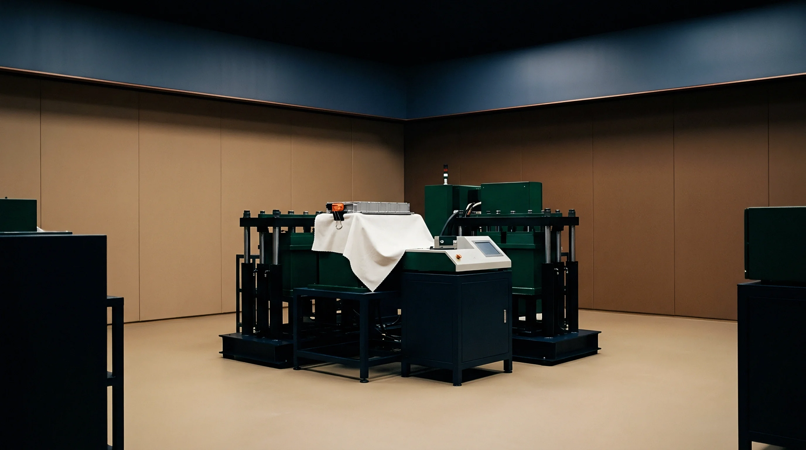
Flame Extension Patterns and Target Panel Impingement
Horizontal jet flare distances recorded during thermal runaway determine side-by-side clearance allowances. Internal pressure build-up behind small seam gaps converts escaping gas streams into torch flames reaching velocities over fifteen meters per second. When horizontal flame extension exceeds twelve inches, side-by-side placement without physical fire barriers is ruled out.
Evaluating radiative flux heat maps at the zero-inch boundary determines whether neighboring cabinets suffer cascading failure. The list below identifies specific physical failure mechanisms observed during unit-level flame testing:
- Gaskets Degradation leads to seam flaming when perimeter silicone seals char, shrink, and drop out under heat exceeding 400 degrees Celsius, creating open blowtorch paths directly targeting adjacent cabinets.
- Latch Mechanism Yielding occurs when internal deflagration pressure deforms door locking rods, allowing cabinet doors to bow outward and release wide-area vertical flame sheets.
- Exhaust Cowling Melt happens when aluminum or plastic deflector cowlings lose structural integrity, shifting vertical vent paths into unconstrained horizontal flame distribution.
- Cable Transit Burnout results from inadequate intumescent sealing at wire entry points, allowing fire paths to penetrate lower cable troughs and spread to adjacent racks.
- Roof Panel Deflection occurs when thin-gauge sheet metal bows upward under internal pressure, opening gaps along the top perimeter that jet high-temperature flames directly toward overhead structures.
Vertical flame plume extension dictates overhead clearance requirements for indoor energy storage rooms and outdoor sheltered canopies. Thermal plumes rising from top exhaust vents can reach temperatures exceeding 900 degrees Celsius at the vent exit, maintaining temperatures above 400 degrees Celsius three meters above the cabinet roof. If overhead structural steel or roof trusses sit within this high-temperature zone, intumescent fireproofing or dedicated heat shield baffles are mandatory.
Evaluating overhead plume boundaries involves mapping temperature decay along the vertical center axis using thermocouple trees positioned directly above primary vent locations.
Intumescent perimeter gaskets that expand five times their original volume at 200 degrees Celsius prevent lateral flame jetting through cabinet seam gaps.
Surface burn patterns on target indicator walls reveal localized heat concentration points that average flux meters miss. Target walls lined with thin sheet metal or wood fiberboards display localized scorching where jet flames or focused radiant hot spots strike. The presence of charring or discoloration on target panels positioned six inches from the test article proves that radiant and convective heat transfer exceeded material ignition thresholds.
Interpreting these patterns requires cross-referencing visual char rings with thermocouple data logs to pinpoint the precise seconds when cabinet seam failure occurred during the thermal event.
Flame duration acts as a primary weighting factor when assessing fire spread severity. Brief flash fires lasting under ten seconds, caused by instantaneous ignition of accumulated vent gas pockets, transfer negligible total energy to adjacent equipment. Sustained flaming lasting ten to forty minutes, driven by progressive cell-to-cell thermal runaway across dense module clusters, elevates adjacent cabinet skin temperatures above critical thermal limits.
Clearance reduction approvals require proving that sustained external flaming is eliminated or confined strictly within engineered internal exhaust stacks that scrub and cool effluent before discharge.
Secondary combustion outside the primary cabinet boundary occurs when uncombusted pyrolytic gases mix with ambient oxygen beyond the exhaust port. In rich vent gas mixtures containing high proportions of carbon monoxide, methane, and hydrogen, gas exiting the vent port remains above its auto-ignition temperature but lacks oxygen inside the cabinet. Once released into open air, the gas stream ignites spontaneously, forming a stationary diffusion flame detached from the cabinet surface.
This secondary combustion zone can extend two to three meters downstream of the vent, creating an intense thermal hazard for any equipment or civil infrastructure situated within that discharge path.
Failure to limit flame extension to engineered exhaust pathways results in immediate rejection of reduced spatial clearance submittals by municipal fire authorities.
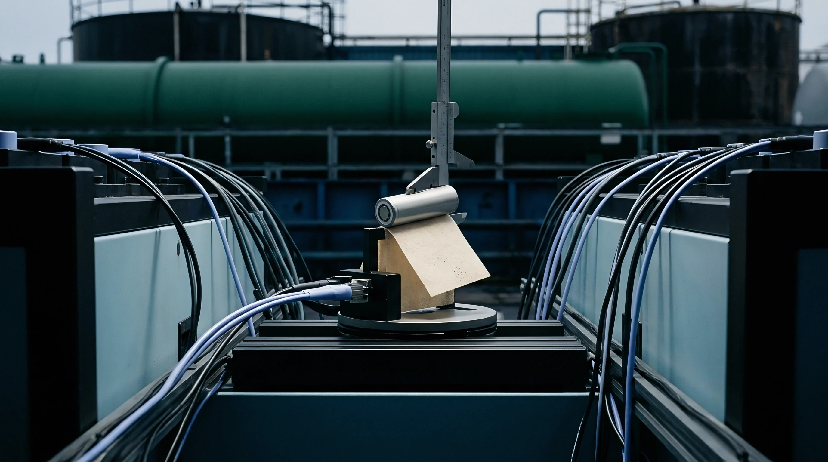

Effluent
Vent gas composition and volumetric release rates recorded during UL 9540A unit testing dictate explosion hazards and ventilation requirements. Thermal decomposition of lithium-ion electrolytes releases complex mixtures of flammable and toxic gases. Interpreting gas generation metrics involves evaluating gas production rates in liters per minute, total gas volume per kilowatt-hour of installed battery capacity, and chemical species fractions.
Hydrogen, carbon monoxide, methane, ethylene, and vaporized carbonate solvents represent the primary flammable constituents that demand rigorous deflagration risk analysis.
Lower flammability limit calculations determine the volume of air required to dilute escaping vent gas below explosive concentrations. Gas chromatography sampling during unit testing establishes the lower flammability limit of the combined gas mixture, which typically ranges between 6% and 12% by volume in air. High hydrogen fractions drop the mixture’s lower flammability limit and drastically increase the fundamental burning velocity, raising the maximum rate of pressure rise during deflagration.
When evaluating zero-clearance configurations, engineers must prove that gas escaping from cabinet pressure relief vents cannot accumulate in narrow interstitial spaces between tightly packed enclosures to reach flammable concentrations.
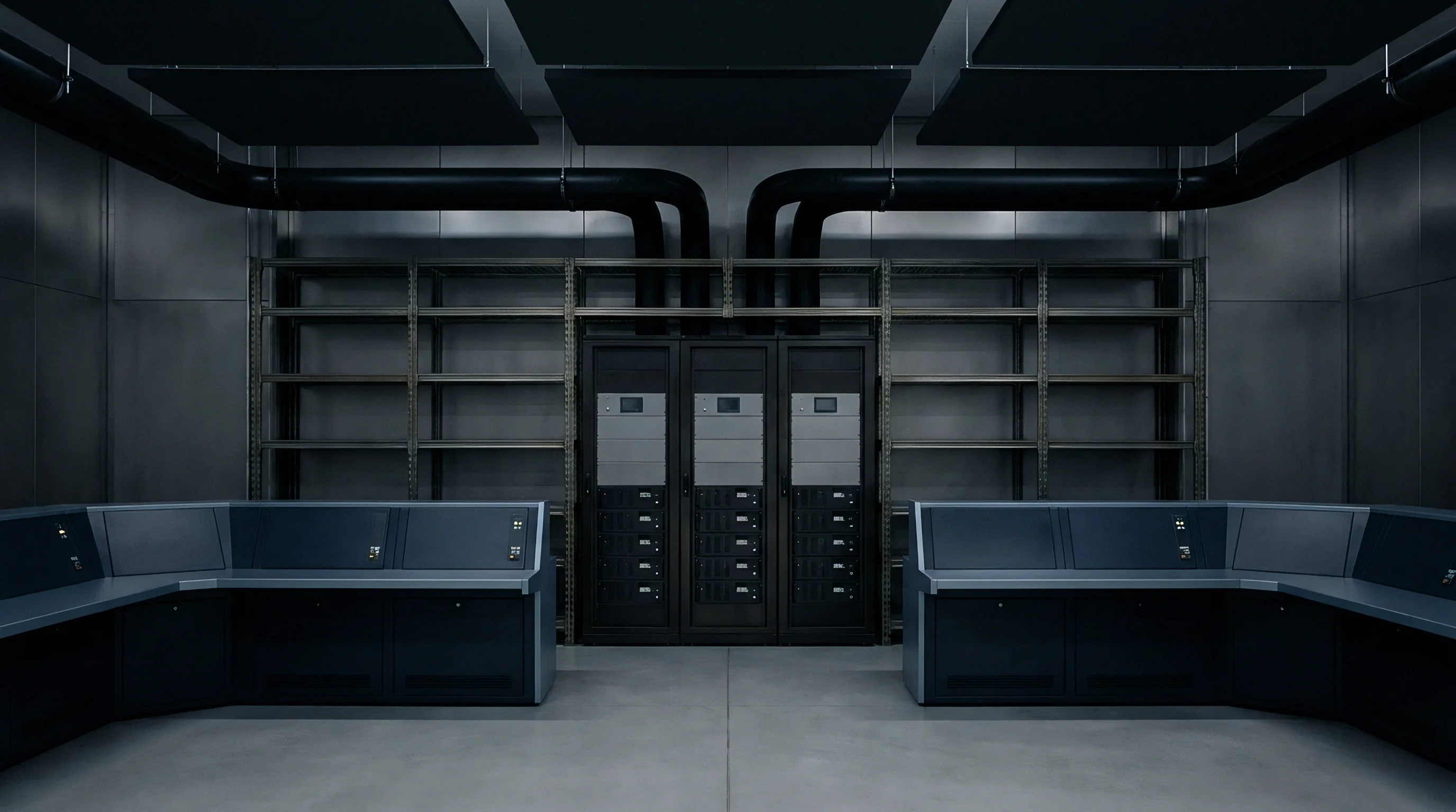
Gas Species Analysis and Deflagration Risk Metrics
Off-gas chemical analysis provides essential parameters for sizing deflagration venting systems under NFPA 68 and deflagration prevention systems under NFPA 69. High concentrations of carbon monoxide present both acute toxicity and long-term flammability risks. Fluorinated compounds, including hydrogen fluoride, generated from the thermal breakdown of polyvinylidene fluoride binders and fluorinated lithium salts, add extreme toxicity hazards to the off-gas plume.
The procedure below outlines the mathematical evaluation required to calculate off-gas accumulation in tight cabinet clearances:
- Determine total volumetric gas release from unit-level test data, expressed in standard cubic meters per kilowatt-hour of battery energy.
- Identify the maximum instantaneous gas generation rate from real-time flowmeter logs recorded during peak cell venting.
- Calculate the combined lower flammability limit of the gas mixture using Le Chatelier’s mixing rule applied to the individual chemical species fractions.
- Compute the available free air volume within the interstitial gap between battery cabinets arranged at reduced clearances.
- Calculate the time required for peak gas generation to displace ambient air in the gap and reach 25% of the calculated lower flammability limit.
- Verify that cabinet exhaust fan displacement or passive draft velocity dilutes the gap volume faster than the peak gas generation fill rate.
Off-gas velocity and directional plume dispersion determine whether vent gases enter building air intakes or collect beneath overhangs. High-velocity vent discharge ejects gases up and away from neighboring units, facilitating rapid atmospheric dispersion. Low-velocity seepage through cabinet door gaskets allows heavy solvent vapors to settle at ground level, filling cable trenches and utility access vaults.
Tracing the path of thermal effluent from the top vent down to the civil clearance boundary highlights this exposure. Settling solvent vapors create persistent flammable gas pockets that can detonate upon contact with secondary electrical ignition sources located meters away from the failing battery rack.
NFPA 69 requires maintaining flammable gas concentrations below 25 percent of the lower flammability limit within confined interstitial spaces between battery cabinets.
Deflagration testing conducted inside closed test chambers evaluates maximum overpressure spikes generated when vent gas ignites within cabinet voids. Internal pressure spikes exceeding 13.7 kilopascals (2 pounds per square inch) threaten structural seam failure unless cabinet blast panels actuate cleanly. Blast panel design must redirect internal pressure upward, venting the explosion energy safely away from adjacent units.
Interpreting chamber pressure logs requires identifying both primary cell venting pressure pulses and secondary deflagration pressure spikes caused by ignition of accumulated gas clouds inside the cabinet structure.
| Chemical Species | LFP Volume Fraction (%) | NMC Volume Fraction (%) | Lower Flammability Limit (% in air) | Fundamental Burning Velocity (cm/s) |
|---|---|---|---|---|
| Hydrogen (H2) | 25 to 40 | 15 to 30 | 4.0 | 210 to 300 |
| Carbon Monoxide (CO) | 30 to 50 | 35 to 55 | 12.5 | 45 |
| Methane (CH4) | 5 to 15 | 5 to 10 | 5.0 | 38 |
| Ethylene (C2H4) | 2 to 8 | 5 to 12 | 2.7 | 68 |
| Carbon Dioxide (CO2) | 10 to 25 | 10 to 20 | Inert gas | Zero combustion contribution |
Airflow mixing dynamics inside narrow array corridors heavily influence off-gas accumulation rates. Wind tunnel and computational fluid dynamics modeling validated against unit-level gas release data show that ambient crosswinds can push vent gas streams back down into adjacent unit gaps, counteracting buoyant thermal rise. When designing reduced clearance field layouts, engineers must evaluate worst-case stagnant air conditions where natural convection alone governs plume dispersion.
If passive draft velocities fall below 0.5 meters per second, mechanical exhaust systems tied to gas detection sensors become mandatory to justify reduced cabinet clearances.
Toxics dispersion modeling uses hydrogen fluoride and carbon monoxide release rates to establish safety perimeter distances for emergency response personnel. Hydrogen fluoride concentrations exceeding 30 parts per million present immediate danger to life and health, requiring specialized protective equipment. When cabinets sit at zero-clearance side-by-side configurations, gas venting pathways must not channel concentrated toxic gas streams into service walkways or firefighter access corridors, ensuring that emergency responders can approach the equipment safely during a thermal event.
Low-toxicity LFP gas generation does not eliminate deflagration risks, as high hydrogen fractions dictate violent explosive capability.

Geometry
Translating unit-level test clearance data into civil installation design requires rigorous dimensional mapping between prototype test configurations and commercial field layouts. UL 9540A unit testing tests specific spatial orientations, including back-to-back, side-by-side, and corner-wall boundary conditions. A test certificate proving zero-inch clearance safety for side-by-side positioning cannot be automatically applied to back-to-back packing unless back-wall thermal boundary testing was explicitly performed.
Civil site engineers use verified unit-level test geometries to optimize real estate footprint, lowering land acquisition and foundation paving costs.
Side-by-side clearance reductions yield the most substantial land footprint savings for outdoor energy storage plants. Prescriptive three-foot gaps between every enclosure create sprawling layout footprints that inflate high-voltage cabling runs, civil site grading expenses, and perimeter security fencing costs. Achieving zero-inch or six-inch side-by-side clearance allows grouping enclosures into continuous multi-megawatt blocks, drastically increasing plant power density.
However, zero-clearance side-by-side arrangements demand that cabinet side walls withstand internal fire temperatures without buckling or transferring dangerous heat flux levels to contiguous enclosures.
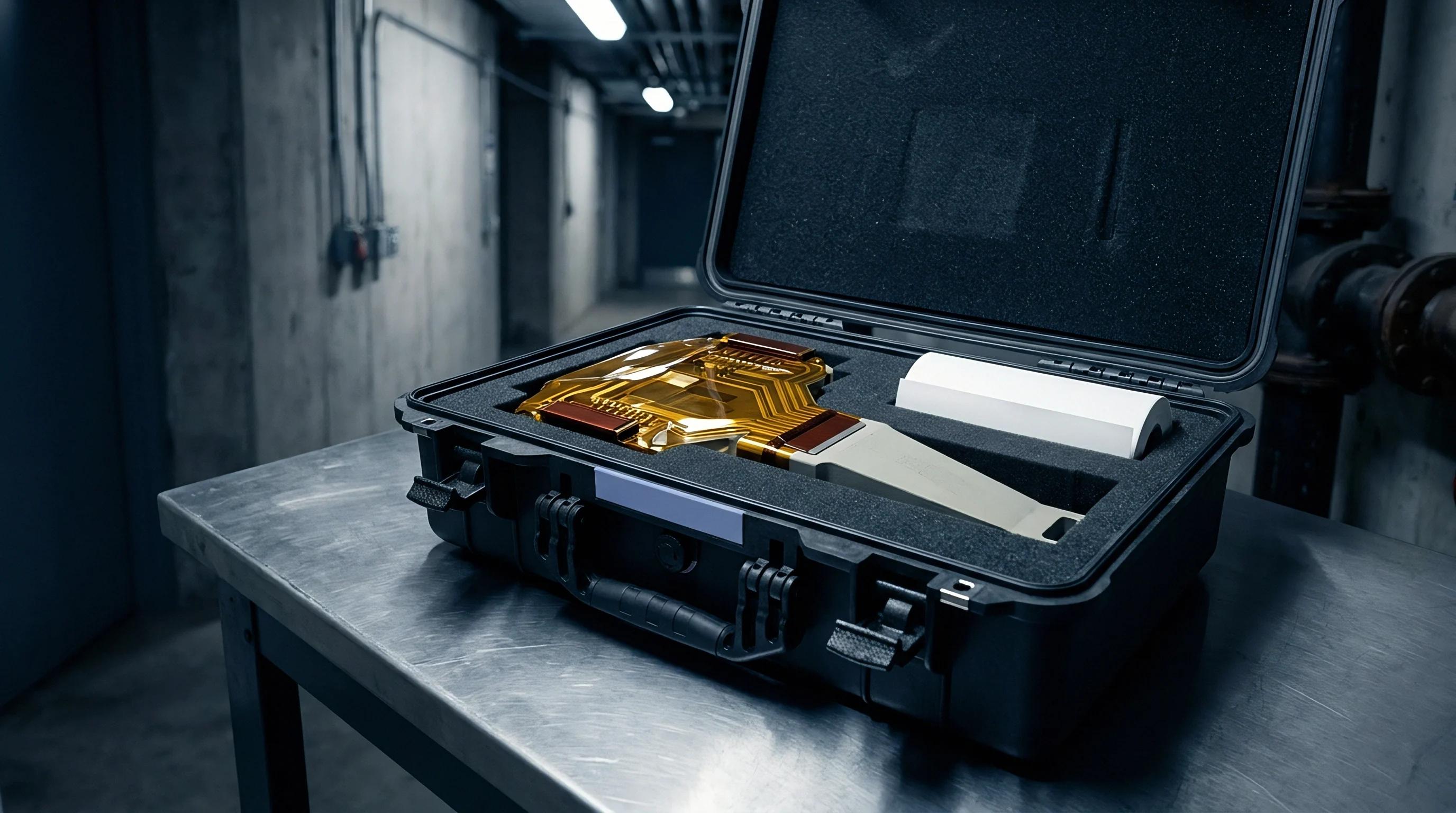
Spatial Configurations and Physical Boundary Mapping
Back-to-back enclosure packing presents unique thermal management and access challenges during fire events. When battery cabinets sit back-to-back with zero separation, exhaust cowlings and rear cable transits sit directly opposite each other. Thermal runaway in one cabinet can vent directly against the rear panel of the facing cabinet if exhaust streams are directed backward.
Evaluating back-to-back test data involves verifying that test setups positioned indicator panels or dummy units directly against the rear skin, proving that internal rear-wall insulation stops cascade propagation across the deep central seam of the block.
Wall proximity testing establishes minimum allowable distances between battery enclosures and structural walls of adjacent buildings. Standard tests evaluate proximity to both non-combustible surfaces, such as reinforced concrete or concrete masonry units, and combustible exterior walls. If a cabinet achieves zero-inch clearance approval against concrete masonry, placing that same cabinet six inches from a wood-framed or composite-clad structure remains a severe fire code violation unless separate combustible-wall test data is provided.
Engineers must verify the exact material composition of test walls used during laboratory trials.
Corner installations create thermal traps where venting flames and hot gases reflect off intersecting walls back onto the cabinet enclosure. Evaluating unit performance in corner geometries requires inspecting thermocouple data from test runs where the unit was placed inside a three-sided wall enclosure. The corner structure restricts ambient air mixing, elevating localized air temperatures around exhaust cowlings and accelerating thermal saturation of exterior cabinet panels.
Clearance submittals for indoor room installations must account for ceiling height above the cabinet roof, ensuring that rising thermal plumes do not ignite overhead structural elements or reflect back down onto adjacent battery racks.
The sequence below defines the spatial review process for translating test geometries to civil site plans:
- Compare proposed field layout dimensions against the exact spatial boundaries instrumented during the UL 9540A unit-level test run.
- Verify that tested side-by-side, back-to-back, and wall proximity standoff distances match or exceed proposed site clearance dimensions.
- Check exhaust cowling vent angles and discharge paths to ensure field units do not direct hot gas streams toward adjacent cabinet air intake louvers.
- Validate that field access maintenance corridors meet minimum municipal fire code dimensions independently of tested thermal clearance allowances.
- Confirm that civil foundation drainage slopes prevent flammable liquid electrolyte spill pooling beneath zero-clearance cabinet arrays.
Spatial clearance constraints directly dictate overall land expenditure and foundation work.
Site layout adjustments that alter airflow paths relative to tested conditions can inadvertently compromise cabinet cooling during thermal runaway events. Mechanical air intakes positioned on cabinet side walls draw cooling air from the interstitial gaps between units. If side clearance is compressed from thirty-six inches to six inches, intake airflow resistance increases, potentially degrading internal HVAC performance under high ambient temperature conditions.
Reviewers check that field auxiliary power systems maintain required cabinet ventilation velocities across restricted clearance corridors to prevent premature thermal stress during normal operation.
| Clearance Configuration | Required Gap Between Units | Footprint Area per 10 MW Block | Civil Site Savings Factor | Fire Barrier Requirement |
|---|---|---|---|---|
| Prescriptive Baseline | 36 inches (0.91 m) | 1,450 m² | Baseline (0%) | None required |
| Reduced Gap Array | 12 inches (0.30 m) | 1,050 m² | 27.5% reduction | Optional thermal baffles |
| Narrow Corridor Layout | 6 inches (0.15 m) | 880 m² | 39.3% reduction | Engineered vent deflectors |
| Zero-Clearance Block | 0 inches (0.00 m) | 680 m² | 53.1% reduction | Mandatory internal fire wall ratings |
Physical arrangement variations between test articles and deployed commercial units frequently invalidate clearance claims during municipal plan reviews. A system tested as a standalone single-rack enclosure cannot claim zero-clearance approval when deployed as a continuous modular array stretching thirty meters in length. The thermal mass and continuous seam boundaries of an extended multi-cabinet string create cumulative heat trapping that a standalone test rack does not simulate.
Engineers must insist on unit-level test reports that utilized multi-unit strings or simulated adjacent thermal masses during testing.
Standard engineering practice uses spatial derating factors when field topography or wind conditions deviate from laboratory environmental controls. Outdoor test facilities typically conduct unit-level burn trials in calm atmospheric conditions or inside large semi-enclosed burn halls. High velocity ambient winds at field installation sites can compress thermal plumes against cabinet walls, creating localized heating effects that exceed laboratory measurements.
Applying a 20% safety margin to tested clearance distances accounts for adverse environmental microclimates encountered in real-world utility deployments.
Section 4.3.2 of NFPA 855 allows authorities having jurisdiction to modify separation distances provided unit-level test data conclusively demonstrates that fire will not propagate to adjacent battery units or structural walls.
Do unit test results override prescriptive spacing across all civil jurisdictions?
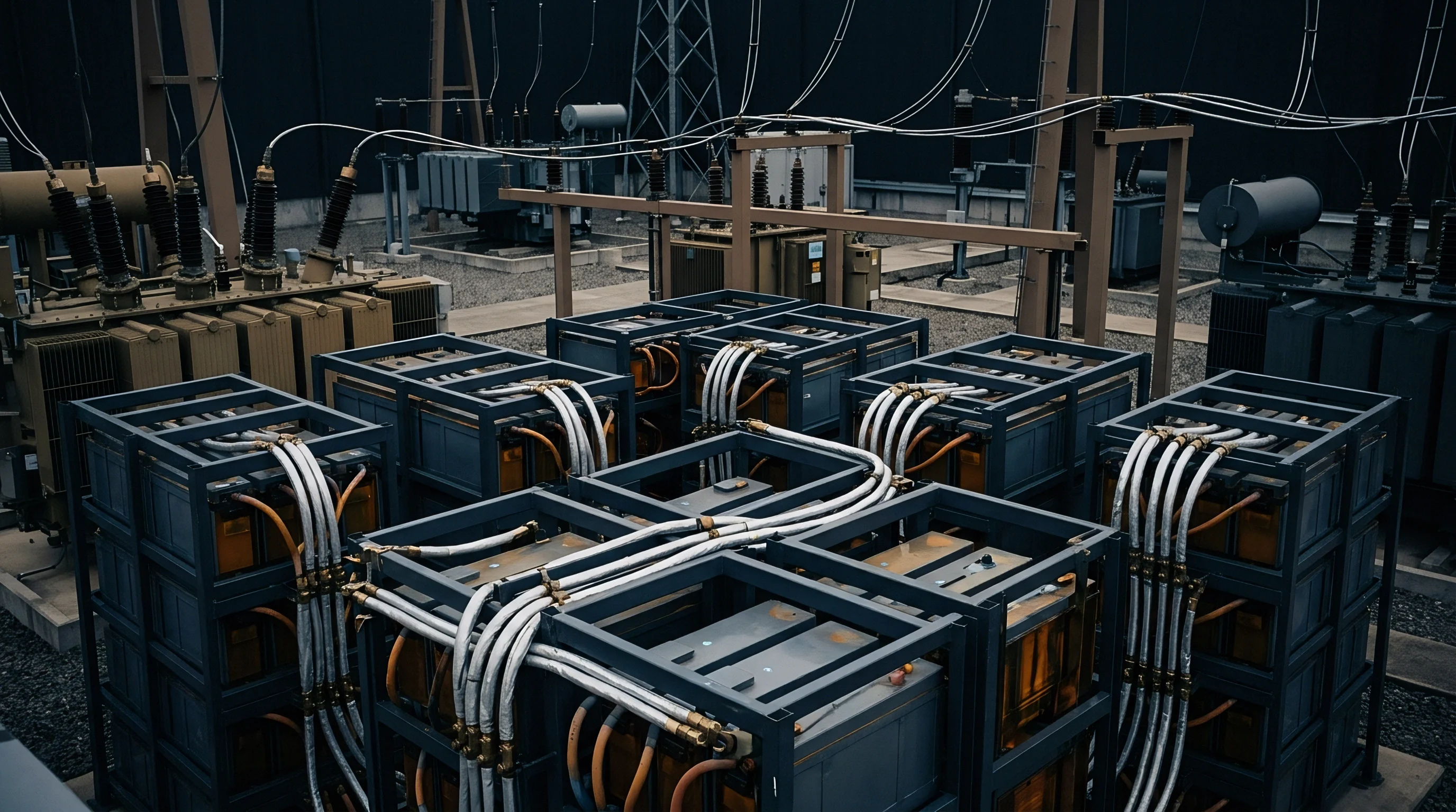

Margin
Applying safety margins to unit-level test data protects energy storage assets against manufacturing variations, end-of-life battery degradation, and extreme environmental operating conditions. A prototype test article hand-assembled in a development laboratory often exhibits superior cabinet seam fit, pristine gasket alignment, and tightly controlled internal wiring compared to mass-produced units coming off automated assembly lines. Safety margins account for tolerance stack-ups and physical aging factors that degrade containment performance over a twenty-year operational lifespan.
Cell state-of-charge during unit testing represents a vital parameter requiring strict analytical margin controls. UL 9540A mandates testing units at 100% state-of-charge or the maximum operational state-of-charge permitted by system control firmware. However, battery cells operated for several years suffer capacity fade and solid electrolyte interphase breakdown, altering off-gas chemistry and thermal runaway reaction rates.
Aged cells can exhibit lower thermal runaway onset temperatures and higher gas generation rates, shifting the combustion intensity of venting plumes. Reviewing test reports requires verifying that cell state-of-charge was rigorously maintained at or above maximum rated thresholds throughout pre-test conditioning.
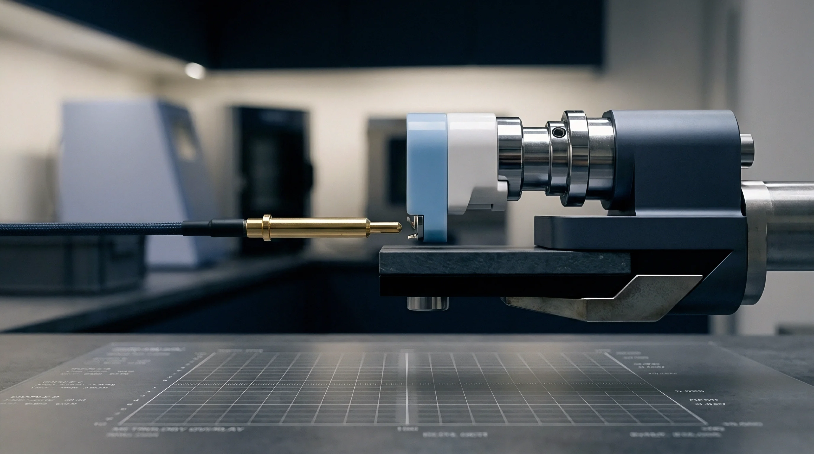
Statistical Variance and Environmental Safety Factors
Manufacturing tolerances in cabinet sheet metal thickness and door seal compression create physical performance variations across production runs. A door latch that flexes two millimeters extra under internal pressure can release high-velocity jet flames that failed to appear during single-article certification testing. Incorporating statistical tolerance analysis into clearance justifications ensures that production units maintain boundary containment even under worst-case mechanical tolerance limits.
The decision checklist below outlines key audit steps for validating unit test safety margins:
- State-of-Charge Verification requires confirming that all test cells reached 100 percent nominal state-of-charge prior to thermal runaway initiation without soft-charging voltage roll-offs.
- Gasket Compression Assessment involves checking that production line door seal torque specifications match the exact gasket compression applied during test article assembly.
- Thermal Baffle Alignment requires inspecting internal fire containment barriers to ensure manufacturing assembly tolerances do not create air gaps exceeding one millimeter.
- Vent Actuation Tolerance involves verifying that explosion relief panels actuate within plus or minus 10 percent of engineered pressure ratings across all operating temperature ranges.
- HVAC Isolation Timing requires confirming that motorized fire dampers close completely within five seconds of gas detection signal activation.
Ambient temperature and altitude corrections adjust laboratory test data to match actual site conditions. UL 9540A unit tests conducted at sea level under standard laboratory conditions of 20 degrees Celsius experience higher ambient air density than high-altitude field installations in mountain regions. Lower atmospheric air density reduces cooling efficiency and alters flame propagation speeds, while high ambient ambient temperatures of 45 degrees Celsius preheat exterior cabinet walls, accelerating thermal saturation during internal runaway events.
Engineers apply thermal derating factors to radiant heat flux data when qualifying installations in desert or high-altitude environments.
Applying a twenty percent safety derating factor to tested radiant heat flux limits compensates for atmospheric density variations at high-altitude installations.
Fire authority reviewers routinely demand additional safety margins when battery chemistry or cell format transitions occur within a certified cabinet product line. Replacing a 280 ampere-hour lithium iron phosphate cell with a 314 ampere-hour cell increases total cabinet energy density without altering structural enclosure dimensions. Although chemical behavior remains similar, the increased fuel mass elevates total heat release and off-gas volumes.
Unless fresh unit-level test data is generated for the higher-capacity cell, clearance submittals must scale measured heat release rates and radiant flux values proportionally to the capacity increase, reducing claimed clearance margins accordingly.
| Operational / Site Condition | Baseline Test Metric | Field Adjustment Multiplier | Derated Boundary Parameter |
|---|---|---|---|
| High Ambient Temperature (>40°C) | Outer Skin Temp: 180°C | 1.15x Thermal Adder | Effective Skin Temp: 207°C |
| High Altitude Site (>1500m) | Off-gas Dispersion Velocity | 0.85x Air Density Factor | Increased Separation Distance |
| Cell Capacity Expansion (+12%) | Peak Heat Release: 220 kW | 1.12x Energy Scaling | Derated Peak HRR: 246.4 kW |
| Production Seam Tolerance | Target Flux: 1.2 kW/m² | 1.25x Safety Multiplier | Design Radiant Flux: 1.5 kW/m² |
Emergency response intervention delays represent a non-quantifiable exposure variable that mandates conservative clearance margins. Unit-level testing measures passive cabinet containment and self-extinguishing capabilities without firefighter intervention. If a thermal event persists for hours, heat soaking through structural cabinet insulation eventually raises neighboring cabinet skin temperatures toward ignition thresholds.
Maintaining conservative clearances ensures that emergency responders have adequate time to establish water supply lines and apply external cooling streams before heat transfer triggers secondary cascading failures across adjacent racks.
Airflow obstruction caused by debris accumulation or snow drift around outdoor enclosures alters passive venting pathways during real-world fires. Snow packed against lower cabinet louvers blocks emergency intake or exhaust pathways, forcing venting gases to exit through upper door seams directly at head height. Engineering safety submittals include clearance buffers around low-level venting structures to guarantee that environmental blockages cannot redirect hazardous off-gas streams toward maintenance access walkways.
Local code officials universally reject clearance reduction requests that rely on unadjusted laboratory test data generated without accounting for production manufacturing tolerances.
Variance
Maintaining regulatory clearance approvals over the long lifespan of an energy storage project requires strict configuration management across all bill-of-materials changes. Battery manufacturers routinely update cell models, alter internal wire harness insulation, adjust BMS firmware control parameters, or swap cabinet component suppliers during multi-year production runs. When a physical or operational change occurs between the certified UL 9540A unit-level test article and current factory floor production units, a critical engineering evaluation must determine whether test clearance validity has been compromised.
Documenting design deviations begins with establishing a formal change control baseline tied to the original UL 9540A test report. Minor changes, such as switching external paint formulations or modifying non-structural interior mounting brackets, rarely impact thermal runaway containment or gas venting behavior. Major modifications, including replacing intumescent perimeter gaskets, altering blast panel release pressures, reducing outer wall insulation thickness, or updating cell chemistries, directly alter thermal boundaries and invalidate existing clearance exemptions.
Comparing the prototype test rack against the commercial production BOM catches undocumented enclosure changes.
Fire code compliance dossiers must reflect true as-built enclosure specifications rather than generic marketing claims or obsolete test certificates. When local fire inspectors perform pre-commissioning site audits, they inspect cabinet nameplates, structural door latch mechanisms, exhaust cowling geometries, and gas detection sensor placements against the engineering drawings submitted during permitting. Discrepancies between field installations and original unit-level test reports can trigger immediate stop-work orders, revoking clearance exemptions and forcing operators to retrofit expensive physical fire walls between closely spaced cabinets.
Re-testing requirements under UL 9540A guidelines follow strict component substitution criteria. If an engineering evaluation proves that a component swap increases thermal transfer rates, increases off-gas volume, or degrades cabinet mechanical strength under deflagration loads, a complete unit-level re-test is mandatory to maintain reduced clearance approvals. In marginal cases, manufacturers may perform targeted engineering analysis or module-level validation tests to prove equivalence, but local Authorities Having Jurisdiction retain ultimate statutory power to reject equivalence arguments and enforce full three-foot prescriptive separations.
Contractual liability for unauthorized configuration changes shifts directly onto system integrators and asset owners who alter equipment without re-certifying boundary safety. Insurance underwriters routinely inspect UL 9540A test dossiers following thermal incidents. If an underwriter discovers that field cabinets incorporated unauthorized structural or cell changes that contributed to fire spread across zero-clearance layouts, coverage claims are denied, exposing operating entities to complete financial loss for damaged plant infrastructure and surrounding properties.
Long-term regulatory compliance depends on maintaining absolute fidelity between certified test articles and deployed factory assets, ensuring that safety-critical clearance reductions remain legally defensible throughout the operating life of the energy storage facility.